Table of Contents
Advertisement
Advertisement
Table of Contents

Related Manuals for CAS NT-500 Series


Summary of Contents for CAS NT-500 Series
- Page 2 Table of Contents 1. Introduction................. 4 2. Features & Main function..........6 3. Technical Specification............7 4. Measure of Appearance............ 9 5. Front Panel................ 10 6. Rear Panel ................. 14 7. Installation & Connection..........15 8. Serial Communication (RS-232C) ....... 17 9.
- Page 3 We are confident that you will find the CAS NT-500 Series will meet all of your most demanding needs. CAS indicator is shaped firmly and delicately designed to coincide with the special requirements of several industrial fields and includes many functions and various external interfaces.
- Page 4 This may interfere with accurate reading. environment. Our Dealers : CAS feels that each of its valued customers should get the best service available. Whether it’s the initial installation of our product, maintenance/repair work, or simply answering questions about our products, CAS Corporation and all of its Authorized Dealers are highly trained to assist you with any need regarding CAS products.
- Page 5 2. Features & Main Functions 1) Features High quality, high accuracy Appropriate for weight and measurement system Easy operation and various options Sub display of 12 digits(VFD) – Only NT-505A RFI/EMI screened Watchdog circuitry (System restoration) Weight back up (Weight memory at sudden power failure) 2) Main Functions Saving of date, time and calculated data at sudden power failure Digital filter function...
- Page 6 3. Technical Specification ■ Analog Part & A/D Conversion Load Cell Excitation Voltage DC 9V, 8 x 350Ω load cells Zero Adjustment Range 0.05mV 20mV ∼ 1.2μV/D (H-44,OIML) Input Sensitivity 0.6μV/D (Non H-44,OIML) System Linearity Within 0.01% of F.S. A/D Internal Resolution 1 / 200,000 5,000 dd (H-44,OIML) A/D External Resolution...
- Page 7 ■ General Specification Power AC 110V/220V, 50/60 Hz Product Size 195(W) x 189(D) x 96 (H) Temperature Range ~ 40 ℃ ℃ Product Weight Approx. 2.5 kg Fuse Capacity T250mA L250V Power Consumption Approx. 10W ■ Options Option 1 RS-422/RS-485 serial interface Option 2 BCD output Option 3...
- Page 8 4. Measure of Appearance...
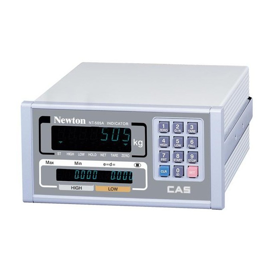
- Page 9 5. Front Panel...
- Page 10 1) Weight display - Display lamp (▼) STABLE lamp : lights up when the weight is stable. HIGH lamp : lights up when the high limit relay is activated. LOW lamp : lights up when the low limit relay is activated. HOLD lamp : lights up when you press HOLD key.
- Page 11 ■ Toggles the display between gross weight weight. and net weight. If tare weight is saved, tare plus item's weight is gross weight and only item's weight is net weight. Used to go to the “SET” mode. ■ Key (Weighed tare entry) Used to weigh an item by using the container.
- Page 12 ■ Model Description Manual tare entry. If the tare weight is previously known press this key, and enter the tare weight by using the numeric keys, NT-501A and then press SET key register it. (Used as MANUAL TARE key). F13 - 0 : Used as STOP key in packer mode. F13 - 1 : Manual tare entry.
- Page 13 6. Rear Panel T250mA ■ PRINTER : Parallel interface port ■ INPUT : External input (Refer to SET mode-F44) OUTPUT : External output (ZERO, HIGH, LOW, FINAL) - Except NT-501A ■ SERIAL : RS-232C/422 ■ FUSE : 250mA 250V fuse. ■...
- Page 14 7. Installation & Connection ※This is L/C connector wire color enclosed with the product 1) Load cell connection Connect load cell connector to load cell port which is in the backside of the indicator. * Connecting method Note 1. In case of 4 wires load cell, connect EX+ with SEN+, and connect EX- with SEN-. Note 2.
- Page 15 2) External input/output port connection If you are away from indicator and you want to press key, please connect the indicator with remote key via rear panel. Multi Connector RELAY ZERO RELAY LOW RELAY RELAY OUTPUT HIGH RELAY (Except NT-501A) FINAL RELAY RELAY OUTPUT COM ZERO/TARE RELEASE/GROSS KEY...
- Page 16 ㅇ 6 Data Set Ready ┌─ ㅇ 4 Request to Send └─ ㅇ 5 Clear to Send 9 pin port(Female) 25 pin port(Male) RS-232C port of NT-500 Series Serial port of computer 3 ㅇ ------------------------- ㅇ 3 Transmit Data 2 ㅇ -------------------------- ㅇ...
- Page 17 7 ㅇ ㅇ 7 Signal Ground 9 pin port(Female) 9 pin port(Male) RS-232C port of NT-500 Series RS-232C port of sub-display 2) Data format ① Baud rate : 1200 bps - 19200 bps Set Baud rate in SET mode. (See F20 at page 30) ②...
- Page 18 * Weight Data (8 byte) a. 13.5kg : ' ', ' ', ' ', ' ', '1', '3', '.', '5' b. 135kg : ' ', ' ', ' ', ' ', '1', '3', '5', ' ' c. -135kg : '-', ' ', ' ', ' ', '1', '3', '5', ' ' 3) Command mode (F22-3 command mode) Command Function...
- Page 19 9. Test Mode 1) How to enter test mode Turn on the power while pressing the key. 2) Available keys key : used for changing preset value. key : used for moving to initial test menu. 3) Test menu (TEST 1~9) TEST 1 : Key test TEST 2 : VF Display test TEST 3 : Load cell test and A/D conversion test...
- Page 20 < Key list > CODE CODE CODE TEST 2 FUNCTION : VF Display test VF DISPLAY DESCRIPTION DISPLAY 8.8.8.8.8.8.8. tESt2 VFd Menu selection TEST 2 is performed. mode ▼▼▼▼▼▼▼ 888888888888 Other keys: Perform test TEST 3 FUNCTION : Load cell test and A/D conversion test VF DISPLAY SUB DISPLAY DESCRIPTION The display shows digital...
- Page 21 Note 2. “Good” message is displayed if the printer connection and specification is done' correctly. If not, “CH 05” message is displayed. Note 3. Test format of printing is as follows. Computer And System CAS Corporation http://www.cas.co.kr TEL 82-2-2225-3500 FAX 82-2-475-4669 TEST OK...
- Page 22 TEST 6 FUNCTION : SRAM test VF DISPLAY SUB DISPLAY DESCRIPTION : Menu selection Good tESt6 rAM SRAM is in normal state. mode Other keys: Perform test TEST 7 FUNCTION : External input/output test DESCRIPTION DISPLAY DISPLAY Menu selection In1 : If you press 1 by mode using external key, and External input :...
- Page 23 10. Calibration Mode 1) How to enter calibration mode ① Remove the bolt on the rear panel and put the switch to CAL ON as figure. Adjusted to CAL ON at factory. ※ Turn on the power while pressing the ②...
- Page 24 CAL 1 (press '1' key to move to CAL 1) FUNCTION : Maximum Capacity Set (range : 1 ~ 99,999) DESCRIPTION DISPLAY DISPLAY : save and go to next menu C = 5000 5000 kg CAL1 CAPA C = 20000 20000 kg set value change : exit...
- Page 25 CAL 3 FUNCTION : Setting Weight In Span CALIBRATION DESCRIPTION DISPLAY DISPLAY : save and go to next menu L = 5000 5000 kg CAL3 SPAn L = 500 500 kg set value change : input the point Note 1. The setting weight should be within the 10 % to 100 % of maximum weight. Note 2.
- Page 26 CAL 5 FUNCTION : Span Calibration DESCRIPTION DISPLAY DISPLAY Load the weight which was set in CAL 3 and press SET key. : span calibration LOAd Under span calibration... - - - - CAL5 LoAd Span calibration is completed. SUCCESS Check whether the displayed : exit weight is same with setting...
- Page 27 CAL 7 FUNCTION : Input weight constant calibration after selecting national code SUB DISPLAY DESCRIPTION DISPLAY enter password PASS CAL7 FACtor Type the password. & finish the CAL mode Note 1. National code is n = 0 Standard, n = 1 Tailand, n = 2 Turkey Note 2.
- Page 28 11. Set Mode 1) How to enter set mode Turn on the power while pressing the key. In weighing mode, press the key for 3 seconds to move to this mode. 2) Available keys key : used for changing preset value. key : used to save changed setting value and go to menu selection mode.
- Page 29 Serial interface F20 Baud rate 1200, 2400, 4800, 9600, 19200bps F21 Parity bit 0 ~ 2 (non parity / even / odd) F22 Transmission method 0 ~ 5 F23 Device number 00 ~ 99 F24 Data format 0 ~ 2 (22 byte / 10 byte / 18 byte) Print F30 Set printer 0 ~ 4...
- Page 30 General setting ① FUNCTION : Change of year, month, day VF DISPLAY SUB DISPLAY DESCRIPTION Set value 98. 03. 02 March 2nd, 1998 F01 dAtE 00. 12. 10 December 10th, 2000 Note 1. Modify the year, month and date by pressing the key.
- Page 31 FUNCTION : Stable condition of weight VF DISPLAY SUB DISPLAY DESCRIPTION Stable lamp is off even with the change of only two division for 3sec. Set value Stable lamp is on if the weight is (00~99) F05 StAbLE changed within five division for 5 sec.
- Page 32 FUNCTION : Hold type VF DISPLAY SUB DISPLAY DESCRIPTION Average Hold Set value (0, 1) F08 HoLd Peak Hold Sampling Hold Note 1. Average hold : Compute the average weight of oscillating weights. Peak hold : Compute the maximum weight among oscillating weights. Sampling hold : Compute the moment weight of oscillating weights.
- Page 33 FUNCTION : Load cell type VF DISPLAY SUB DISPLAY DESCRIPTION Set value Compression or tension load cell (0, 1) F12 L-tyPE Compression and tension load cell FUNCTION : A use of 8 and 9 key VF DISPLAY SUB DISPLAY DESCRIPTION Set value 8 / 9 key : START / STOP key (0, 1)
- Page 34 FUNCTION : Data transmission VF DISPLAY SUB DISPLAY DESCRIPTION No data transmission Transmit data in a state of stable & unstable Set value Transmit data only in stable state (0 ~ 4) F22 SENd Transmit data only in command mode Transmit data if you press PRINT key(PRT) Transmit data if you input Device ID...
- Page 35 FUNCTION : Serial data format VF DISPLAY SUB DISPLAY DESCRIPTION 22 bytes - CAS format Set value (0 ~ 2) F24 S-ForM 10 bytes - CAS format 18 bytes - AND format Print function ③ FUNCTION : Printer VF DISPLAY...
- Page 36 Note 1. Serial No. is available 1 to 999 and initialized to 1 after “GRAND TOTAL” printing Or power-off. Note 2. Weigh No. is available 1 to 999 and is not initialized to 1 after power-off. If you want to initialize it, set F33 to ON in SET mode. 【...
- Page 37 : print, others : Do not print) Actually 1st data to 255 is printed. Note 3. Designate as follows if you want to add company name “CAS” on print format. P00-032( ASCII code 32 : Data start), P01-067( ASCII code 67 : character C)
- Page 38 Note 4. ASCII code table CODE CHA CODE CHA CODE CHA CODE CHA CODE CHA CODE SPACE “ & ‘ < > FUNCTION : Line feed of paper VF DISPLAY SUB DISPLAY DESCRIPTION 1 line feed Set value (1 ~ 9) F35 FEEd 5 line feed 9 line feed...
- Page 39 External input/output function ④ F40 (Except NT-501A) FUNCTION : Relay mode VF DISPLAY SUB DISPLAY DESCRIPTION Limit Mode Checker Mode Set value (0 ~ 4) F40 rELAY Limit Type Checker Mode Packer Mode Relay is not used <Limit Mode> Note 1. When the scale is stable over the high limit, Final relay is ON. Note 2.
- Page 40 < Checker Mode > Note 1. When the scale is stable, LOW, HIGH and FINAL relays are ON after passing the certain time of start delay and then Off after passing the certain time of end delay. Start delay time of finish relay is set in F41 and end delay time of finish relay is set in F42.
- Page 41 < Packer Mode > F41 (Except NT-501A) FUNCTION : Start delay time of finish relay VF DISPLAY SUB VFD DESCRIPTION No delay Set value (0.0 ~ 9.9) F41 dELAY1 Delay for 1.3 sec Delay for 5.5 sec...
- Page 42 F42 (Except NT-501A) FUNCTION : End delay time of finish relay VF DISPLAY SUB VFD DESCRIPTION No delay Set value (0.0 ~ 9.9) F42 dELAY2 Delay for 1.3 sec Delay for 5.5 sec F43 (Except NT-501A) FUNCTION : Range of zero relay VF DISPLAY SUB VFD DESCRIPTION...
- Page 43 External input/output function ⑤ FUNCTION : Relay mode VF DISPLAY SUB VFD DESCRIPTION No option Set value (0 ~ 2) BCD OUT F60 oPtlon Analog option (Vout : 0 - 10V), (Iout : 0 - 24mA) FUNCTION : Relay mode VF DISPLAY SUB VFD DESCRIPTION...
- Page 44 FUNCTION : Maximum output of analog VF DISPLAY SUB VFD DESCRIPTION Maximum output of Analog at 01000 1000kg Set value Maximum output of Analog at (0 ~ 24000) F64 A-CAPA 20000 20000kg Maximum output of Analog at 21315 21315kg FUNCTION : Logic of BCD output VF DISPLAY SUB VFD DESCRIPTION...
- Page 45 12. Weighing Mode (1) Zero Compensation VF Display and use key Platform Description Small variations in the scale’s Step 1 Empty zero ☞ Step 2 Remove small variations in Step 3 Empty the scale’s zero. Note 1. Set zero range to ±2% or ±10% of maximum capacity in F10. (See page 30.) Note 2.
- Page 46 (3) Change of digital filter. VF Display and use key Platform Description Step 1 Item Weighing mode ☞ Press the key for 3 Step 2 You can go to SET mode seconds. Step 3 Item SET mode ☞ Press the , or Step 4 SET Menu 4...
- Page 47 (4) How to save ID code VF Display and use key Platform Description Step 1 Empty Put item Step 2 (“iron”) ☞ Step3 Press the Step 4 ☞ Step 5 ID code of "iron" item Step 6 (“iron”) ☞ Step 7 Save ID item Step 8...
- Page 48 (5) How to enter high limit value (Except NT-501A) VF Display and use key Platform Description Step 1 Empty The display shows previous high ☞ Step2 Press the limit value. ☞ Press Step 3 Enter high limit value(500.0kg) keys. ☞ Step 4 Save Press the...
- Page 49 (6) How to enter high fall limit value (Except NT-501A) VF Display and use key Platform Description The sub display shows Step 1 Empty high limit value. (500.0kg) The display shows previous ☞ Step2 high_fall limit value. ☞ Step 3 Enter high_fall limit value(5.2㎏) ☞...
- Page 50 (7) How to clear ID data VF Display and use key Platform Description Empty Step 1 (or item) ☞ Step2 Press the for 3 seconds. Empty Step 5 All data of id (0~50) is cleared. (or item) Note. Even though there is an item on the platter, data clearing is performed. (8) How to print subtotal.
- Page 51 (9) How to print grand total VF Display and use key Platform Description ☞ Step 1 Grand total printing Note. Grand total means the total weight of all ID cord. The print form is as belows. - - - - - - - - - - - - - - - - - - - OVERALL-TOTAL - - - - - - - - - - - - - - - - - - - DATE...
- Page 52 13. Options OP - 1 RS-422 Serial Interface ▣ Transmission mode : Same as RS-232C interface ▣ Signal format : Same as RS-232C ▣ Data format : Same as RS-232C ▣ Connecting method of RS-422 port IN(+) 1ㅇ --------------------------------- ㅇ 2 Transmit Data(+) OUT(-) 4ㅇ...
- Page 53 ▣ CONNECTION OF PIN SIGNAL SIGNAL Ground (GND) High : Net, Low : Gross 1×10 N.C. 2×10 4×10 8×10 1×10 2×10 4×10 8×10 1×10 2×10 4×10 External Vcc 8×10 External Vcc 1×10 2×10 4×10 8×10 High : +, Low : - 1×10 Decimal point : 10 2×10...
- Page 54 1. BCD data output : Positive, Negative logic 2. Polarity output : “+” = High 3. OVER output : “OVER” = High 4. BUSY output : “BUSY” = High ▣ Standard Accessory : Mating connector 57-30500(Amphenol) Male 1EA. ▣ Weight Data ▣...
- Page 55 OP - 3 Analog Output Interface (0~24mA) (0~10V) (1) Current output ▣ Specification Output Current Max. 0~24 mA Resolutions Over 1/1000 Temperature Coefficient 0.01%/℃ Max. Load Impedance 500Ω MAX. ▣ How to set switch Model : NT -500 ① ② 0~24mA Fixing ③...
- Page 56 ▣ Setting output current You can set output current in F61 and F62 of Set mode. The setting range is 0.000 ㎃ to 24.000 ㎃, by steps of 0.001 ㎃. - Max. capacity : 100 ㎏, Min. capacity : 0.05 ㎏ case F61 : 4000, F62 : 20000 ①...
- Page 57 (2) Voltage output ▣ Specification Output voltage 0 ~ 10V Resolution over 1/1000 Temperature coefficient 0.01%/℃ ▣ How to set switch Model : NT -500 ① ② 0~10V Fixing selection ③ ▣ When the weight is 0, output voltage is 0V. When the weight is maximum capacity is the scale, output voltage is 10V.
- Page 58 14. Sealing Method ① Rear panel sealing ② Load cell connector sealing...
- Page 59 CH 04 ▣ Reason You pressed any key for long time or there is a problem in key part. ☞ Trouble-shooting If there is no problem in key part, call your CAS dealer. CH 05 ▣ Reason Failure of print connection.
- Page 60 (2) CAL mode CH 11 ▣ Reason The resolution exceeds the 1/10,000. ☞ Troubleshooting Lower the resolution. Change the maximum capacity in CAL1 or change the division in CAL2 so that the resolution should be below 1/10,000. CH 12 ▣ Reason The weight for span calibration is lower than 10%, or greater than 100% of the maximum capacity of the scale.
- Page 61 MEMO...
- Page 62 MEMO...
- Page 63 MEMO...
- Page 64 MEMO...
- Page 65 MEMO...
Need help?
Do you have a question about the NT-500 Series and is the answer not in the manual?
Questions and answers
آلارم ch02 برای چیه
The CH02 alarm indicates that the display weight is greater than the maximum capacity set on the CAS NT-500 Series scale. This condition may damage the load cell.
This answer is automatically generated