Table of Contents
Advertisement
Advertisement
Table of Contents

Subscribe to Our Youtube Channel
Related Manuals for CAS CI-400 Series


Summary of Contents for CAS CI-400 Series
- Page 2 Cautions for Your Safety Please comply with 'Cautions for Your Safety', which will lead you to use the product safely and properly to prevent any dangerous situations. ■ Cautions are divided into 'Warning' and 'Alert', which mean as follows. ■ Keep this manual in a place where product users can find out, after finish reading it.
- Page 3 Warning Never disassemble, repair or retrofit the Ensure the power plug to be fully Ensure the grounding of the product. product. inserted to prevent shaking. Poor grounding might cause failure or It might exclude the product from the Any instable connection might cause electric shock upon electric leak.
- Page 4 It might cause the weighing error or failure. Our Dealers : CAS feels that each of its valued customers should get the best service available. Whether it’s the initial installation of our product, maintenance/repair work, or simply answering questions about our products, CAS Corporation and all of its Authorized Dealers are highly trained to assist you with any need regarding CAS products.
-
Page 5: Table Of Contents
Contents 1. Features ................. 1-1. Features ................... 8 1-2. Main Functions ................8 1-3. Analog and A/D Conversion ............9 1-4. Digital and Display ................ 9 1-5. Product Specifications ..............10 1-6. Standard Specification ..............10 1-7. Option Specification ..............10 2. Specifications in Appearance ............. - Page 6 In addition, it is designed for the user-friendly programs for the easier use of indicator by any user with the built-in message display functions to help users understand the product. Please use the product right and sufficiently utilize functions of CI-400 series as you read this manual thoroughly before using CI-400 series.
-
Page 7: Features
1. Features 1-1. Features ■ High speed, High accuracy ■ High speed micro processor adoption ■ A/D conversion speed : Maximum 200 times/sec ■ Appropriate for weight and measurement system ■ Easy operation and various options. ■ Simple and prompt Full Digital Calibration (SPAC : Single pass automatic span Calibration) ■... -
Page 8: Analog And A/D Conversion
1-3. Analog and A/D Conversion Input sensitivity 0.3 uV/D(Certification), 0.2 uV/D(None) Zeroing range 0 ~ 2 mV/V Loadcell supply voltage DC 5V Maximum signal input voltage 3.0mV/V ZERO : ±10 PPM / ℃ Zero variation with temperature SPAN : ±10 PPM / ℃ Input Noise ±0.6㎶... -
Page 9: Product Specifications
1-5. Product Specifications Power SMPS - AC 100-240 V~ , 50-60 Hz, 0.2 A Product Size 185(W) x 102(D) x 92(H) -10 ℃ ~ +40 ℃ Temperature Range Product Weight Approx. 1.2 kg Fuse Capacity 0.5 A L250 V Power Consumption Approx. -
Page 10: Specifications In Appearance
2. Specifications in Appearance 2-1. External Dimension... -
Page 11: Front Panel Descriptions
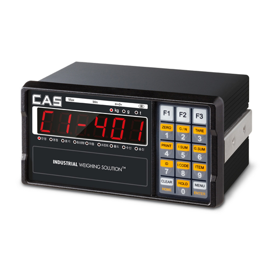
2-2. Front Panel Descriptions CI-401 ■ Display Information Main Function STABLE Indicated when the weight is stable Indicated when the weight is “0” ZERO TARE Indicated when tare is entered Indicates gross and net weight after setting tare AUTO Indicated when the Data Print-out is Automatic during Stable Weight PRINT Indicated during data transmission to an External Print communication Port HOLD... - Page 12 CI-405 ■ Display Information Main Function STABLE Indicated when the weight is stable Indicated when the weight is “0” ZERO TARE Indicated when tare is entered Indicates gross and net weight after setting tare Indicated when Step1 Relay ON is output. Indicated when Step2 Relay ON is output.
- Page 13 CI-407 ■ Display Information Main Function STABLE Indicated when the weight is stable Indicated when the weight is “0” ZERO TARE Indicated when tare is entered Indicates gross and net weight after setting tare Indicated when Step1 Relay ON is output. Indicated when Step2 Relay ON is output.
-
Page 14: Keyboard
2-3 Keyboard Function Key * Adjust the weight display near the zero-set to 0. (2 %, 5 %, 10 %, 20 %, 100 % ranges can be selected.) * * For every press, alternate between total/net load and display the weight with the lamp indicator. - Page 15 * Use to change the Set Point. * Use when weighing a moving object. * Use to enter the menu mode. * Can be customized to suit the needs. Editor Key It enters 0~9 in the input numeric mode * Use when deleting all input. * Use to enter the menu mode...
-
Page 16: Rear Panel Descriptions
2-4. Rear Panel Descriptions ■ LOAD CELL : Port for connection. 6Wires Loadcell ■ C/L : Current loop Interface Port ■ RS-232 : Serial Interface Com Port (COM1, COM2) ■ RS-422/485 : Serial Interface Com Port (RS-422/485) ■ AC INPUT : AC 100 – 240 V~ (50-60 Hz) ara available. FUSE –... -
Page 17: Installation & Connection
3. Installation & Connection 3-1. Loadcell Connection Connect the load cell connector to the load cell port which is in the backside of the indicator. * Connection method Color Function EXC+ EXC- WHITE SIG+ GREEN SIG- BLUE SHIELD SEN+ BROWN SEN- BLACK Note 1. - Page 18 * Relationship between the load cell output and input sensitivity. Applied voltage of load cell x Output voltage of load cell x Value of a division 0.2 uV ≤ ------------------------------------------------------------------------------------------------ Rated capacity of load cell x Number of load cell Example 1) Number of load cell: 4 ea Rated capacity of load cell: 500 Kg Rated output of load cell: 2mV/V...
-
Page 19: Weight Setup(Calibration) Mode
4. Weight Setup (Calibration) Mode What is the weight setup? It refers to the calibration to set the displayed value to the actual weight in displaying weights. How to Access to the Weight Setup Mode Remove the blot on the rear panel and connect both of CAL pin(check picture below) And turn on the power supply and push the key same time, you can access to weight setup mode... -
Page 20: Weight Setup(Calibration) Menu
4-1. Weight Setup(Calibration) Menu (CAL1 – CAL9) CAL 1 : Maximum capacity calibration CAL 2 : Minimum division calibration CAL 3 : Zero-set and span calibration CAL 4 : Hopper weight setting CAL 5 : Direct calibration CAL 6 : Zero adjustment CAL 7 : Factor calibration CAL 8 : Gravity adjustment CAL 9 : Setting dual range... - Page 21 CAL 2 (Minimum division calibration) Function: Minimum division and decimal position setting Range of set value: 0.001 ~ 50 Used key Display Descriptions d= 0.001 Minimum division 0.001 kg Using numeric keys 0.01 Minimum division 0.01 kg Enter minimum division Minimum division 0.1 kg = Set, =Cancel...
- Page 22 CAL 3(Zero-set and span calibration) CAL 3-1 Function: Setting Multi Calibration Step Range of set value: 1 ~ 5 Used key Display Descriptions Setting multi calibration for step 1 STEP- 1 (CAL3-3 and CAL 3-4 are carried out Using numeric keys once) Set the multi step, Setting multi calibration for step 5...
- Page 23 CAL 3-3 Function: Setting Weight Range of set value: 1 ~ 99,999 Used key Display Descriptions Using numeric keys It means the weight setting mode. LOAD 1 (Number = multi calibration number) W=100.00 100.00 (unit: Kg or Ton) Set the counterweight values 0.10 0.10 (unit: Kg or Ton)) = Set,...
- Page 24 CAL 4(Hopper weight setting) CAL 4-1 Function: Setting Multi Calibration Step Range of set value: 2 ~ 5 Used key Display Descriptions Using numeric keys Setting multi calibration for step 2 STEP- 2 (for hopper system) Set the range. Setting multi calibration for step 5 STEP- 5 (for hopper system) = Set,...
- Page 25 CAL 5(Direct Calibration) CAL 5-1 Function: Direct input about the zero value of loadcell Range of set value: 1 ~ 99,999 Used key Display Descriptions Using numeric keys ZE-CAL Direct zero input mode 0.0000 Loadcell zero = 0.0000 mV/V Enter the output value. 0.1000 Loadcell zero = 0.1000 mV/V = Set,...
- Page 26 CAL 6(Zero-set adjustment) Function: Zero adjustment - calibration when any zeroing error occurs. Used key Display Descriptions Empty the load tray and press the setup 2-CAL key. The current weight value is displayed. 1234 = Set, =Cancel Confirm 'Stable' and press the setup key. - - - Zero adjustment in progress...
- Page 27 CAL 8(Gravity correction) Function: Gravity Adjustment Used key Display Descriptions It means you accessed to the G-CAL menu for the gravity adjustment. Using numeric keys Enter an initial gravity value. Gr-CAL Set the gravity for the production 9.XXXX = Set, =Cancel place.
- Page 28 CAL 9-2 Function: Setting the applied section for the Dual Range Range of set value: 0 ~ 99999 Used key Display Descriptions Dual range is applied to less than M 1000 1000kg. Using numeric keys Dual range is applied to less than M 5000 Enter dual values.
-
Page 29: How To Seal The Indicator(Sealing)
4-2 How to Seal the Indicator (Sealing) -
Page 30: Weighing Mode
5. Weighing Mode (1) Zero-set Function (used when changing the zero-set) Display Part or Used Keys Load Plate Description Step 1 Empty State with zero changed Step 2 Push the zero key State after performing zero function. Step 3 Empty Namely, the current weight is designated as ' 0 'kg. - Page 31 (3) Product number changing Display Part or Used Keys Load Plate Description Step 1 Press ID key. Step 2 Product Number : 1 Step 2 Change the product number. Step 3 Item number is saved. (4) Item number changing Display Part or Used Keys Load Plate Description Step 1...
- Page 32 (5) Set point changing Display Part or Used Keys Load Plate Description Step 1 Press Item key. Displayed current setpoint Step 2 number. Step 2 Change the set point value Step 3 Set point is saved Repeat step1~3 until end Step 4 point of max set point (6) Subtotal Print...
- Page 33 Reference 1. The print format is designated as below. -------------------------------------------- SUB-TOTAL --------------------------------------------- DATE 2012/ 1/ 1 TIME 09:30 COUNT TOTAL 350.0 kg Reference 2. The subtotal DATA is automactically or manually deleted based on the menu number[F3-03]. (7) Total Print Display Part or Used Keys Load Plate Description...
-
Page 34: Test Mode
6. Test Mode How to enter test mode Press the key whilst in normal mode and select test mode by pressing or when the power is turned on while pressing key in the front of the indicator. Push the key in the test mode to return to weighing mode. Test Menu (1 –... - Page 35 TEST 1 Key Test Function: Key test Used key Display Descriptions When you press any key to test, the KEY 01 number and code for the key are : Next Menu displayed on the screen. Other keys : Test < Key List > Code Code Code...
- Page 36 TEST 3 AD Test Function: Load cell test and A/D conversion test Used key Display Descriptions : Cancel The internal value for the current XXXXXX weight value is displayed. : Next Menu Reference 1. Press to display the load cell output as m/V units. TEST 4 Communication Test Function: Serial Communication Test Used key...
- Page 37 TEST 6 External Input/output Test (OPTION) Function : External Input / Output Test Used key Display Descriptions Displayed in the external input section when I - X O - X there is an external input. ---------- : Next Menu Push 1~6 key to execute weighing external I - 2 O –...
- Page 38 TEST 9 BCD OUT Test (OPTION) Function : BCD-OUT Test Used key Display Descriptions BCD Out automatically increases the output 111111 : Next Menu value per digit by 1 Other keys : Test Reference 1. This test operates only if BCD out Option Card is mounted. TEST 10 Memory Test Function: Memory Test Used key...
-
Page 39: Set Mode
7. Set Mode How to enter set mode Press whilst in normal mode and select Set Mode by pressing key. After testing in set mode, press to enter weighing mode. Classification Menu SubMenu 1. General Setting F1.01 Set AD speed (1. - Page 40 Classification Menu SubMenu 2. Communication F2.01 Set Device ID Setting F2.02 Set Data Transmission Rate (2. COMM) F2.03 Set COM1 Port Setting F2.04 Set COM1 Baud Rate F2.05 Set COM1 Out Data F2.06 Set COM1 Output Format F2.07 Set COM1 Output mode F2.08 Set COM2 Port Setting F2.09...
- Page 41 Classification Menu SubMenu 4. Option Setting F4.01 Adjust Zero(Aout) (4. OPTION) F4.02 Adjust Span(Aout) F4.03 Max Weight(Aout) F4.04 BCD Out Type Classification Menu SubMenu 5. Device Function F5.01 Set value Initialize (5. DEV) F5.02 Set Date F5.03 Set Time F5.04 Set Password Classification Menu...
- Page 42 1) General Function Menu-F1.01: Set AD Speed Function AD Speed Setting Display Part Meaning 1-01. Converting speed 5 times per second 1-01. Converting speed 10 times per second 1-01. Converting speed 20 times per second 1-01. Converting speed 40 times per second Set Range (0~8) 1-01.
- Page 43 Menu-F1.04: Set Band Stop Filter Function Band Stop Filter Setting Display Part Meaning Set Range 1-04 : XX Band Stop Filter use setting. (0: Not use, 1: Use) (0 ~ 1) Initial Value : 0 Set Range H-FrEq Band Stop Filter High Frequency setting.. (1 ~ 1600) Initial Value : 60 Set Range...
- Page 44 Menu-F1.08: Set Weight Back-up Function Weight Back-up Setting Display Part Meaning Set Range 1-08. 0 Weight back up function is not used (0, 1) 1-08. 1 Weight back up is used (based on operation) Menu-F1.09: Set Hold Type Function Hold Type Setting Display Part Meaning Average Value Hold...
- Page 45 Menu-F1.13: Set Automatic Hold Canceling Conditions Function Automatic Hold Canceling Conditions Setting Display Part Meaning Set Range Hold is canceled when the value is changed by more 1-13. XX (00 ~ 99) Initial Value : 10 Than 00 % of the hold value Menu-F1.14: Set Key Operating Conditions Function Key Operating Conditions(Zero, Tare) Setting...
- Page 46 Menu-F1.19: Set use Key Lock Function Key Lock use Setting Display Part Meaning Set Range 1-19. 0 Unlock front key (0, 1) 1-19. 1 Lock front key Menu-F1.20: Set F1 Key Use Type Function F1 Key Use Type Setting Display Part Meaning 1-20.00 F1 Key used as the tare/tare cancelling key...
- Page 47 Menu-F1.22: Set F3 Key Use Type Function F3 Key Use Type Setting Display Part Meaning 1-22.00 F3 Key used as the tare/tare cancelling key 1-22.01 F3 Key used as the total/net weight key 1-22.02 F3 Key used as the Hold key 1-22.03 F3 Key used as the Holdless key 1-22.04...
- Page 48 2) Communication Setting Menu-F2.01: Equipment Number Function Equipment Number Display Part Meaning Set Range 2-01. XX (0 ~ 99) Desired device ID may be entered. Initial Value : 0 Reference 1. This function can be used as the indicator unique ID when using COMMAND mode. Menu-F2.02: Data Transfer Speed Setting Function Data Transfer Speed Setting...
- Page 49 (0 ~ 3) 2-06. 2 18 byte Format(AND, FINE) 2-06. 3 22 byte of CAS with relay status Reference 1. Refer to <Appendix 1> for the communication format Menu-F2.07: COM1 Communication Method Function COM1 Communication Method (RS-232C - Output mode)
- Page 50 22 byte of CAS Set Range 2-11. 1 10 byte of CAS (0 ~ 3) 2-11. 2 18 byte Format(AND, FINE) 2-11. 3 22 byte of CAS with relay status Reference 1. Refer to <Appendix 1> for the communication format...
- Page 51 Menu-F2.12: COM2 Communication Method Function COM2 Communication Method (RS-232C - Output mode) Display Part Meaning 2-12. 0 Data is not transmitted 2-12. 1 Transmitted only if the print key is pushed 2-12. 2 Transmitted in both stable/unstable cases (Stream Mode) 2-12.
- Page 52 10 byte of CAS (0 ~ 3) 2-16. 2 18 byte Format(AND, FINE) 2-16. 3 22 byte of CAS with relay status Reference 1. Refer to <Appendix 1> for the communication format Menu-F2.17: RS-422/485 Communication Method Function RS-422/485 Communication Method (Output mode)
- Page 53 Display Part Meaning Printer is not used 3-01. 0 Set Range 3-01. 1 CAS DEP Ticket Print Standard Type (0 ~ 3) 3-01. 2 CAS DLP Label Print Standard Type 3-01. 3 CAS BP Label Printer Menu-F3.02: Set Print Form...
- Page 54 Item Number 2 byte Item Name 10 byte Print count 3 byte Date 10 byte Time 8 byte CAS BP Series Printer Protocol Parameter Description Data Length Gross Weight 7 byte Tare Value 7 byte Net Weight 7 byte Net (‘.’...
- Page 55 (032: print, all others: do not print) and everything is printed from data 1 until data 255. Reference 3. To add company name "CAS" to the existing print format, designate as follows P00-032 (ASCII code 32: data starts),...
- Page 56 Menu-F3.06: Set Printing Delay Time Function Set Printing Delay Time Display Part Meaning Set Range 3-06. 1 (0 ~ 200) Issue print after 00 x 10ms Initial Value: 1 Menu-F3.07: Set Print Condition Function Set Print Condition Display Part Meaning Set Range 3-07.
- Page 57 4) Option Setting Menu-F4.01: Adjust zero of A-out Function Adjust the Zero Output upon Using Analog Out option Display Part Meaning 0000 0.000mA, 0V output Set Range 4000 4.000mA, 2V output (0 ~ 24000) 4015 4.015mA, 2.007V output Menu-F4.02: Adjust Span of A-out Function Adjust the Maximum Output upon Using Analog Out option Display Part...
- Page 58 5) Hardware Set Function Menu-F5.01: Set Value Initialization Function Set Value Initialization Display Part Meaning No set values of the product are initialized to factory shipping Set Range 5-01. 0 state (0, 1) All set values of the product are initialized to factory shipping 5-01.
- Page 59 6) Relay Setting CI-401 : Menu-F6.01 CI-405 : Menu-F6.01 ~ F6.12(Relay Output Setting : 62p) CI-407 : Menu-F6.01 ~ F6.13(Relay Output Setting : 78p) *Menu-F6.02 ~ : Relay Option Card Setting Menu. Menu-F6.01: Set External key Function Set External key Display Part Input1 Input2...
- Page 60 █ Relay Option Card Setting (CI-405, CI-407) Menu-F6.02: Set External key Function Set External key Display Part Input1 Input2 Input3 Input4 6-02. 0 ZERO TARE TARE_C PRINT 6-02. 1 ZERO TARE/C HOLD HOLD_C 6-02. 2 ZERO TARE/C I-SUM PRINT Set Range 6-02.
- Page 61 █ CI-405 Relay Output Setting Menu-F6.03: Relay Mode Function Relay Mode Display Part Meaning 6-03. 0 Limit Mode 1 (Step 4 Contact Point A Output) 6-03. 1 Limit Mode 2 (Fall and Weighing Decision) 6-03. 2 Packer Mode 1 (Stepl4 Contact Point B Output) 6-03.
- Page 62 Weighing Output Information per Mode Relay Mode OUT 1 OUT 2 OUT 3 OUT 4 OUT 5 OUT 6 Step 1 Step 2 Step 3 Step 4 0_Limit Mode1 Completed Zero (SP1 ≤ W) (SP2 ≤ W) (SP3 ≤ W) (SP4 ≤...
- Page 63 Menu-F6.04: F_Relay Delay Start Time Function Set Start Delay Time for completed Relay(T1) Display Part Meaning Set Range 6-04. 10 (0~99) Initial Value: Delayed by 00 x 0.1 Sec 10 x 0.1 Sec Menu-F6.05: F_Relay Operating Duration Function Set Operating Duration Time for completed Relay(T2) Display Part Meaning Set Range...
- Page 64 Menu-F6.09: Relay Operating Range Function Relay Operating Range Display Part Meaning 6-9. 0 Relay is operating in only +(weight) range Set Range 6-9. 1 Relay is operating in only -(weight) range (0 ~ 2) 6-9 2 Relay is operating in +,-(weight) range Menu-F6.10: Delay Time of Start (Not Used Relay Type_I) Function Set Delay time of start...
- Page 65 █ CI-405 Relay Timing graph <Limit mode 1> Relay Operation Graph upon Setting (F6.03-0) 1. Required set value input : SP4 > SP3 > SP2 > SP1 2. T1 : Refer to F6.04 (Delay time of weighing Finish relay output) T2 : Refer to F6.05 (Operation time of weighing Finish relay output) 3.
- Page 66 <Limit mode 2> Relay Operation Graph upon Setting (F6.03-1) 1. Set value input requirement : (SP2 – SP4) > (SP1 – SP3) 2. T1 : Refer to F6.04 (Delay time of weighing Finish relay output) T2 : Refer to F6.05 (Operation time of weighing Finish relay output) T5 : Refer to F6.08 (Operation(ON) time of Weighing NG relay output) 3.
- Page 67 <Packer Mode 1> Relay Operation Graph upon Setting (F6.03-2) 1. Required set value input : SP4 > SP3 > SP2 > SP1 2. T1 : Refer to F6.04 (Delay time of weighing Finish relay output) T2 : Refer to F6.05 (Operation time of weighing Finish relay output) 3.
- Page 68 <Packer Mode 2> Relay Operation Graph upon Setting (F6.03-3) 1. Set value input requirement : (SP2 – SP4) > (SP1 – SP3) 2. T1 : Refer to F6.04 (Delay time of weighing Finish relay output) T2 : Refer to F6.05 (Operation time of weighing Finish relay output) T5 : Refer to F6.08 (Operation(ON) time of weighing NG relay output) 3.
- Page 69 <Checker mode1> Relay Operation Graph upon Setting (F6.03-4) 1. Required set value input : SP4 > SP3 > SP2 > SP1 2. T3 : Refer to F6.06 (Delay time of judgment-relay output) T4 : Refer to F6.07 (Operation time of judgment-relay output) 3.
- Page 70 <Checker mode2> Relay Operation Graph upon Setting (F6.03-5) 1. Required set value input : SP2 > SP1 2. T3 : Refer to F6.06 (Delay time of judgment-relay output) T4 : Refer to F6.07 (Operation time of judgment-relay output) T5 : Refer to F6.08 (Operation(ON) time of weighing NG relay output) 3.
- Page 71 <Checker mode3> Relay Operation Graph upon Setting (F6.03-6) 1. Required set value input : SP4 > SP3 > SP2 > SP1 2. Each output relay will output if it reaches the set value or is within the range 3. Relay Output Step1 : ON when Near Zero ≤...
- Page 72 <Checker mode4> Relay Operation Graph upon Setting (F6.03-7) 1. Required set value input : SP2 > SP1 2. T3 : Refer to F6.06 (Delay time of judgment-relay output) T4 : Refer to F6.07 (Operation time of judgment-relay output) T5 : Refer to F6.08 (Operation(ON) time of weighing NG relay output) 3.
- Page 73 <Checker mode5> Relay Operation Graph upon Setting (F6.03-8) 1. Required set value input: SP2 > SP1 2. T3: Refer to F6.06 (Delay time of judgment-relay output) T4: Refer to F6.07 (Operation time of judgment-relay output) T5: Refer to F6.08 (Operation(ON) time of weighing NG relay output) 3.
- Page 74 <Auto Tare Packer Mode> Relay Operation Graph upon Setting (F6.03-9) 1. Set value input requirement : (SP2 – SP4) > (SP1 – SP3) 2. T1: Refer to F6.04 (Delay time of weighing Finish relay output) T2: Refer to F6.05 (Operation time of weighing Finish relay output) T5: Refer to F6.08 (Operation(ON) time of weighing NG relay output) 3.
- Page 75 <Auto Tare Auto Packer Mode> Relay Operation Graph upon Setting (F6.03-10) 1. Set value input requirement : (SP2 – SP4) > (SP1 – SP3) 2. T1 : Refer F6.04 (Delay time of weighing Finish relay output) T2: Refer to F6.05 (Operation time of weighing Finish relay output) T5: Refer to F6.08 (Operation(ON) time of weighing NG relay output) T6: Refer to F6.11 (Restart delay time after finish output) 3.
- Page 76 <Auto Zero Auto Packer Mode> Relay Operation Graph upon Setting (F6.03-11) 1. Set value input requirement : (SP2 – SP4) > (SP1 – SP3) 2. T1: Refer to F6.04 (Delay time of weighing Finish relay output) T2: Refer to F6.05 (Operation time of weighing Finish relay output) T5: Refer to F6.08 (Operation(ON) time of weighing NG relay output) T6: Refer to F6.11 (Restart delay time after finish output) 3.
- Page 77 █ CI-407 Relay Output Setting Menu-F6.03: Relay Mode Function Relay Mode Display Description Limit Mode (Fall and Weighing Decision) 6-03. 0 6-03. 1 Packer Mode 6-03. 2 Loss in weight (3 Step Discharging Mode) 6-03. 3 1 Step Feeding, 2 Step Discharging Mode_1 Set Range 6-03.
- Page 78 Weighing Output Information per Mode Relay Mode OUT 1 OUT 2 OUT 3 OUT 4 OUT 5 OUT 6 Lower Limit Upper 0_Limit Mode Step 1 Step 2 Step 3 Zero Limit NG 1_Packer Mode Step 1 Step 2 Step 3 Finish Error Zero...
- Page 79 Menu-F6.04: F_Relay Delay Start Time Function Set Start Delay Time for completed Relay Display Part Meaning Set Range 6-04. 10 (0~99) Initial Value: Delayed by 00 x 0.1 Sec 10 x 0.1 Sec Menu-F6.05: F_Relay Operating Duration Function Set Operating Duration Time for completed Relay Display Part Meaning Set Range...
- Page 80 Menu-F6.10: Relay Operating Range Function Relay Operating Range Display Part Meaning 6-10. 0 Relay is operating in only +(weight) range Set Range 6-9. 1 Relay is operating in only -(weight) range (0 ~ 2) 6-9 2 Relay is operating in +,-(weight) range Menu-F6.11: Delay Time of Start Function Set Delay time of start...
- Page 81 █ CI-407 Relay Timing graph <Limit mode Relay Operation Graph upon Setting (F6.03- 0) > 1. Required set value input : Final(SP7) > Step 1(SP1) > Step 2(SP2) > Fall(SP3) 2. SP1: Step1, SP2: Step 2, SP3: Fall, SP5: Upper Limit NG , SP6: Lowest Limit NG , SP7: Final 2.
- Page 82 <Packer mode> Relay Operation Graph upon Setting (F6.03-1) 1. Required set value input : Final (SP7) > Step 1(SP1) > Step 2(SP2) > Fall (SP3) 2. SP1: Step1, SP2: Step2, SP3: Fall, SP5: Upper Limit NG , SP6: Lowest Limit NG , SP7: Final 3.
- Page 83 <Loss in weight_3 Step Discharging Mode > Relay Operation Graph upon Setting (F6.03-2) 1. Required set value input : Final (SP7) > Step 1(SP1) > Step 2(SP2) > Fall (SP3) 2. SP1: Step1, SP2: Step2, SP3: Fall, SP5: Upper Limit NG , SP6: Lowest Limit NG , SP7: Final 3.
- Page 84 <1 Step Feeding, 2 Step Discharging Mode_1> Relay Operation Graph upon Setting (F6.03-3) 1. Required set value input : Step 1(SP1) > Final(SP7) > Step 2(SP2) > Fall(SP3) 2. SP1: Step1, SP2: Step2, SP3: Fall, SP5: Upper Limit NG , SP6: Lowest Limit NG , SP7: Final 3.
- Page 85 <1 Step Feeding, 2 Step Discharging Mode_2> Relay Operation Graph upon Setting (F6.03-4) 1. Required set value input : Step 1(SP1) > Final(SP7) > Step 2(SP2) > Fall(SP3) 2. SP1: Step1, SP2: Step2, SP3: Fall, SP5: Upper Limit NG , SP6: Lowest Limit NG , SP7: Final 3.
- Page 86 <2 Step Feeding, 1 Step Discharging Mode> Relay Operation Graph upon Setting (F6.03-5) 1. Required set value input : Step 2(SP2) > Step 1(SP1) > Final (SP7) > Fall (SP3) 2. SP1: Step1, SP2: Step2, SP3: Fall, SP5: Upper Limit NG , SP6: Lowest Limit NG , SP7: Final 3.
- Page 87 <3 Step Discharging Mode_1> Relay Operation Graph upon Setting (F6.03-6) 1. Required set value input : Step 3(SP3) – Fall(SP8) > Step 2(SP2) > Step 1(SP1) 2. SP1:Step1, SP2:Step2, SP3: Step3, SP5: Upper Limit NG , SP6: Lowest Limit NG , SP7: Final, SP8:Fall 3.
- Page 88 <3 Step Discharging Mode_2> Relay Operation Graph upon Setting (F6.03-7) 1. Required set value input : Step 3(SP3) – Fall (SP8) > Step 2(SP2) > Step 1(SP1) 2. SP1:Step1, SP2:Step2, SP3: Step3, SP5: Upper Limit NG , SP6: Lowest Limit NG , SP7: Final, SP8:Fall 3.
- Page 89 <2 Step Feeding, 2 Step Discharging Mode_1> Relay Operation Graph upon Setting (F6.03-8) 1. Required set value input : Step 2(SP2) > Step 1(SP1), Step 4(SP4) – Fall(SP8) > Step 3(SP3) 2. SP1: Step1, SP2: Step2, SP3: Step3, SP4: Step4, SP5: Upper Limit NG , SP6: Lowest Limit NG , SP7: Final, SP8: Fall 3.
- Page 90 <2 Step Feeding, 2 Step Discharging Mode_2> Relay Operation Graph upon Setting (F6.03-9) 1. Required set value input : Step 2(SP2) – Supply Fall(SP8) > Step 1(SP1), Step 4(SP4) – Discharge Fall(SP9) > Step 3(SP3) 2. SP1: Step 1, SP2: Step 2, SP3: Step 3, SP4: Step 4, SP5: Upper Limit NG , SP6: Lowest Limit NG , SP7: Final, SP8: Supply Fall, SP9: Discharge Fall 3.
- Page 91 Standard) External Input Connector Pin Information Ext In Pin Map Pin No Signal Ext In 1 Ext In 2 Ext In 3 Ext In 4 In Common(GND)
-
Page 92: Relay In4 / Out6
8. OPTION 8-1 Relay In4 / Out6 █ General 4 External Input 6 External Output(Relay out) Operating temperature range : -10℃ ~ 40℃ Connector : Terminal Block - 12 Pin Item Specification Max. 100 mΩ at 6V Resistance (Initial) , 1A Contact Data... - Page 93 █ Connection of Input & Output Input (A Contact) Output(A Contact)
-
Page 94: Analog Out
8-2 Analog Out CN2 Pin Map Pin No Signal I-OUT V-OUT SHILED █ General V-Out 0~10V I-Out 0~20mA I-Out 0~24mA I-Out 4~20mA Fixing / Flexibility Setting Operating temperature range : -10℃ ~ 40℃ Connector _ Terminal Block - 5 Pin... - Page 95 ▶ SPECIFICATIONS Max. Impedance Output Precision V-OUT 0~10V(DC) Over 1/1000 500Ω MAX I-OUT 0~24mA Over 1/1000 ▶ V-out Equivalent Circuit ▶ I-out Equivalent Circuit ※ V-out output puts out Analog voltages(0~10V) proportional to the signal input displaying the weight ※ I-out output is adjusted so as to be 4 mA when the weight display is 0, and 20 mA when it is the maximum load, ▶...
-
Page 96: Bcd-Out
8-3 BCD-OUT CN2 Connection Diagram ▶ Only use in NPN Type of PLC DIGITX_1 DIGITX_2 General █ Operating temperature range : -10℃ ~ 40℃ Connector _ DB-36Pin (CHAMP 57-40360(Amphenol-Female) The Parallel BCD out is the interface that indicates the weight in display as BCD code The Inner circuit of input/output circuit is electronically disconnected by photo coupler... - Page 97 CN2 Pin Map Pin No Signal Pin No Signal 1st Digit - 1×10 5th Digit - 1×10 1st Digit - 2×10 5th Digit - 2×10 1st Digit - 4×10 5th Digit - 4×10 1st Digit - 8×10 5th Digit - 8×10 2nd Digit - 1×10 6th Digit - 1×10 2nd Digit - 2×10...
-
Page 98: Bcd-In
8-4 BCD-IN CN2 Connection Diagram █ General Operating temperature range : -10℃ ~ 40℃ Connector _ D-SUB-9 Pin(Female) User can changing the Item code through BCD In card The Inner circuit is disconnected electronically by photo coupler. - Page 99 CN2 Pin Map Pin No. Signal Pin No. Signal 1st Digit - 1×10 2nd Digit - 1×10 1st Digit - 2×10 2nd Digit - 2×10 1st Digit - 4×10 2nd Digit - 4×10 1st Digit - 8×10 2nd Digit - 8×10 Ground(GND)
-
Page 100: Serial Communication
9. Serial Communication 9-1 RS-232C Port Connection ① PC Connect ㅇ ㅇ 2 Receive Data ------------------------- ㅇ ㅇ 3 Transmit Data -------------------------- ㅇ ㅇ 7 Signal Ground -------------------------- ┌─ ㅇ 8 Carrier Detect ├─ ㅇ 20 Data Terminal Ready └─ ㅇ... -
Page 101: Current Loop
② How to Connect a Label Printer (DLP) ㅇ ㅇ 2 Receive Data -------------------------- ㅇ ㅇ 3 Transmit Data -------------------------- ㅇ ㅇ 5 Signal Ground -------------------------- CI-400 RS-232C Port DLP Printer RS-232 Port 9-2 Current loop Current Loop Interface has stronger resistance to electric noise than the RS-232C Interface; therefore, it is more favorable for intermediate-distance transmissions. -
Page 102: Rs-422/Rs-485 Serial Communication (Option)
9-3 RS-422/RS-485 Serial Communication (Option) RS-422 & 485 transmit signals with the voltage difference, which are more stable for electric noises than other communication methods. In addition, the AC power cable or other electric wires should be placed separately, and the shield cable (0.5Φ... -
Page 103: Appendix
Data (8 bytes) └──┘ └──┘ └──┘ US (Unstable) GS (Gross Weight) Unit (kg/t) ST (Stable) NT (Net Weight) OL (Overload) * 22 Bytes for CAS (Relay status) Data (8 bytes) CR LF └──┘ └──┘ │ │ │ └──┘ US (Unstable) - Page 104 *Weight Date (8 byte) Byte No Example weight ‘ ‘ ‘ ‘ ‘ ‘ ‘ ‘ ‘1’ ‘3’ ‘.’ ‘5’ 13.5kg ‘ ‘ ‘ ‘ ‘ ‘ ‘ ‘ ‘1’ ‘3’ ‘5’ ‘ ‘ 135kg ‘-‘ ‘ ‘ ‘ ‘ ‘...
- Page 105 Appendix 2> Command Mode 1 Description CAS <NT-500 Command> Indicator Reception Function Indicator Response dd RW CR LF Request for Weight Data Transmit the data in the set format upon command input Execute the zero and retransmit dd MZ CR LF to PC...
- Page 106 Appendix 3> Command Mode 2 Description CAS <NT-570 Command> Reference 1. Command Mode Table Command data to NT-570A Command description NT-570A Respond ZERO key Z CR TARE key Return the received T CR GROSS key Return the received G CR...
- Page 107 Appendix 4> Command mode 3 Description CI-400 : Transmission only if data is requested ( 1 byte communication) Appenix 5> ASCII Table CHA CODE CHA CODE CHA CODE CHA CODE CHA CODE CHA CODE Space “ & ‘ < >...
- Page 108 Appendix 6>MODBUS-RTU PROTOCOL The registry read and write shown below of MODBUS-RTU protocol can be managed based on the requirements included in the reference document regarding the Modicon PI-MBUS-300 standard. For selection of communication with Modbus-RTU, the serial communication settings paragraph has been included.
- Page 109 FUNCTION 3: Read holding registers Request Register1 Address Function No. register 2 bytes Address 0x03 0x0000 0x0002 Total. bytes = 8 Reply Address Function No.byte Register1 Register2 2 bytes 0x03 0x04 0x0064 0x00C8 Total. bytes = 3 + 2*No. register + 2 -number of register = number of modbus register to be read, start at address 1 register.
- Page 110 Communication Error Management The management of communication data error must be controlled by CRC (cycle redundancy check). If a communication error occurs, the slave does not reply to any request. The master must consider the time-out before receiving the reply. If no reply is received, it can be inferred that a communication error has occurred.
- Page 111 Register List The Modbus-RTU protocol registers capable of being executed in this instrument are as follows. R = Register that can be used as read-only W= Register that can be used as write-only R/W = Register that can be used as for both read and write H = Higher word of the Double word composing the register L = Lower word of the Double word composing the register Saving to...
- Page 112 40038 Ext_Output 40042 Analog out Span Weight H 0~99999 40043 Analog out Span Weight L 0~99999 40044 Analog out Zero Adjust H 0~99999 40045 Analog out Zero Adjust L 0~99999 40046 Analog out Span Adjust H 0~99999 40047 Analog out Span Adjust L 0~99999 Analog Out V-Out range 0~99999...
- Page 113 40066 ADC reserved 40067 ADC reserved 40068 ADC reserved 40081 Stable range 0~99 40082 Zero tracking range 0 : OFF Weight back up 40083 1: ON 40084 Zero key range 0~99 40085 Tare key range 0~99 Initial zero range 0~99 40086 Overload range 40087...
- Page 114 40173 Set Date 40174 Set Hour 40175 Set Minute Set Second 40176 40177 Set use Alibi memory 40178 reserved 40199...
-
Page 115: Error Message
11. Error Message 11-1 Errors that can occur in weight calibration mode Error Cause Solution Lower resolution. Resolution = maximum allowed weight/value of 1 increment. The set resolution has exceeded the Err 20 Adjust maximum allowed weight in CAL 1 of weight calibration allowance limit of 1/30,000. -
Page 116: Error Message From The Weighing Mode
11-2 Errors that can occur in weighing mode Error Cause Solution Due to unstable load the weighing scale cannot Move the weighing scale to a flat, vibration-free Err 01 be reset. surface and turn on the power. Load cell is not properly connected or there is a Check if the main body and the load plate are Err 02 problem with the A/D convertor. - Page 117 MEMO...
- Page 118 MEMO...
- Page 119 MEMO...
Need help?
Do you have a question about the CI-400 Series and is the answer not in the manual?
Questions and answers