Table of Contents
Advertisement
Advertisement
Table of Contents

Related Manuals for CAS WEIGHING SOLUTION NT-200 Series


Summary of Contents for CAS WEIGHING SOLUTION NT-200 Series
-
Page 2: Table Of Contents
7. Installation................. 13 8. Test Mode................14 9. System Mode..............17 10. Calibration Mode............22 11. Function Mode..............31 12. How to use ............... 43 13. Communication.............. 47 14.CAS & Command Mode Protocol......49 15. Error Message & Trouble Shooting......53... -
Page 3: Precaution
This may interfere with accurate reading. Our Dealers: CAS feels that each of its valued customers should get the best service available. Whether it’s the initial installation of our product, maintenance/ repair work, or simply answering questions about our products, CAS Corporation and all of it’s Authorized Dealers are highly trained to assist you with any need regarding... -
Page 4: Introduction
Each indicator is subjected to several levels of quality control before it leaves the factory. CAS indicator is shaped firmly and delicately designed to coincide with the special requirements of several industrial fields and includes many functions and various external interfaces. -
Page 5: Features & Main Function
2. Features & Main Function Features ( Appropriate for Weight and Measurement System ( Easy Operation ( Full Digital Calibration ( Weight Back-Up [ Weight Memory at Sudden Power Failure ] ( 4 Multi-Point Calibration ( Command Mode Function (Control by PC – Request and Set the Data) ( Kg/lb Conversion &... -
Page 6: Specification
3. Specification Load Cell & A/D Conversion Load Cell Excitation Voltage DC 5V (Connectable up to 6 EA) Zero Adjustment Range 0.05 mV ~ 5 mV Input Sensitivity 2 Uv / D (OIML, Ntep, KS) 0.5 uV / D (Non OIML, Ntep, KS) Non-linearity 0.01% Full Scale A/D Internal Resolution... -
Page 7: Dimensions
4. Dimension NT-200A, NT-201A NT-200S, NT-201S... -
Page 8: Front Panel
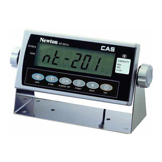
5. Front Panel NT-201A Display Lamp STABLE Measured Weight is stable On : Net OFF : Gross ZERO Current Weight is 0 kg HOLD Hold function is activated TARE ◁ Tare is activated ACCUMULATION This state is in accumulation mode COUNT MODE It is in count mode &... - Page 9 NT-200A Display Lamp STABLE Measured Weight is stable ZERO Current Weight is 0 kg TARE Used to weigh an item by using the container Toggles the display between gross & net weight HOLD Hold Function is activated Key Board Used to enter setting value in TEST, CAL, and SET mode instead of Numeric keys ▲...
- Page 10 ZERO KEY Used to remove small variations in the indicator’s zero If pressed for 2~3 sec, you can go to SYSTEM Mode TARE KEY Used to weigh an item by using the container Current weight is memorized as tare weight If pressed in unload condition, tare setting is released If pressed for 2~3 sec, you can go to KeyTare Mode When you know the tare weight, you can enter the tare weight...
-
Page 11: Rear Panel
6. Rear Panel NT-200A, NT-201A NT-200S, NT-201S CAL S/W Calibration Switch Bolt POWER Port for Power LOAD CELL Port for connecting Load Cell Serial Interface COM1, COM2 Port RS-232C [connect to PC, Printer] Ground Terminal [ Frame Ground ] If it is not connected, it may cause trouble... -
Page 12: Installation
7. lnstallation Load Cell Connection Connect load cell connector to load cell port which is in the backside of indicator. Note: Wire color can be different depending on the manufacturer or Load cell’s model COLOR COLOR 1 (EXC+) 5(SHIELD) SHIELD 2 (EXC-) WHITE 6 (SEN+) -
Page 13: Test Mode
8. Test Mode ( How to Go to Test Mode To go to Test mode, press the [TARE]+[UNIT] key in starting mode until being displayed the message of “tESt” . In Test mode, Back-light is On. ( Test Menu(TEST1 – TEST6) Test 1 : Key test Test 2 : A/D conversion test Test 3 : Serial interface(Com1) test (RS-232) - Page 14 TEST 2 A/D Conversion TEST (Load Cell Test) FUNCTION DISPLAY DESCRIPTION UNIT Go to TEST3 tESt 2 TEST 2 Condition TEST 2 is performed automatically 24750 This value can be changed Note 1. Check the numeric by loading and unloading a weight. If the numeric is not changed or it is o, check the connection of the load cell.
- Page 15 TEST 4 RS - 422/485 TEST with Computer (RS - 422/485 : Option) FUNCTION DISPLAY DESCRIPTION ZERO Transmit ‘0’ TARE Transmit ‘1’ tESt 4 TEST 4 Condition NET/GRS Transmit ‘2’ PRINT Transmit ‘4’ ----- Waiting for Transmission & reception ENTER Transmit ‘8’...
-
Page 16: System Mode
9. System Mode How to Go to System Mode If you press the [ZERO] key for 2~3 seconds in weighing mode. you can see the “SyS” on the display after showing “on”. And then you can move to any mode where you want to go using the G/N key. SYSTEM MODE MODE [G/N] key... - Page 17 COUNT MODE( ) Ⅱ INITIAL DISPLAY DESCRIPTION Counting Mode ( ) Press the [TARE] key long to set the Count Mode in detail Ⅱ DISPLAY DESCRIPTION Input the weight of unit with sample, ZERO and go to count weighing mode SAMP = Z Input the weight of unit with key value, TARE...
- Page 18 PERCENT MODE(Ⅲ) INITIAL DISPLAY DESCRIPTION Percent Mode (Ⅲ) Press the [TARE] key long to set the Percent Mode in detail DISPLAY DESCRIPTION After weighing the weight of 100%, ZERO go to the percent weighing mode SAMP = Z After weighing the weight of 100% with key, TARE go to the percent weighing mode In = t...
- Page 19 ■ The use of key in the Counter & Percent Weighing Mode DESCRIPTION The current value of counter or Short percent set to zero ZERO Long Move to System mode Short Save the value of tare TARE Long Enter the count or percent mode to set value Short Display the weight of Gross or Net in turn GROSS/NET...
- Page 20 ACCUMULATION MODE(Ⅳ) INITIAL DISPLAY DESCRIPTION Accumulation Mode ■ The use of key in the Accumulation Mode DESCRIPTION Short The current value sets to zero ZERO Long Move to System mode Short Save the value of tare TARE Refer to the 12 - 4. Long HOW to INPUT the VALUE OF TARE with ID Short...
-
Page 21: Calibration Mode
10. Calibration Mode mV/V (full span) Multi-point Multi-point Real curve Ideal Multi-point Multi-point Multi-point weight (zero span) Zero and Span points to interpolate weight from Load Cell ■ How to Go to Calibration Mode Unfasten a Cal Switch Bolt on the rear side of indicator and then turn on power while pressing CAL switch. - Page 22 * Weight Calibration :: ( ZERO KEY - UNIT : 0 : kg 1 : lb CAL 0 : Multi Calibration Setting CAL 1 : Maximum Capacity Setting CAL 2 : Minimum Division Setting CAL 3 : Zero Calibration CAL 4/6/8/10 : A Weight Setting (First~Fourth) CAL 5/7/9/11 : Span Calibration (First~Fourth)
- Page 23 CAL 1 MAXIMUM CAPACITY SETTING Available Setting Range : 1kg ~ 999,999kg FUNCTION DISPLAY DESCRIPTION CAL 1 CAL 1 Condition Increase or decrease 5000 5000kg set value Move one digit to left 10000 10000kg ENTER Next Menu Save the value and go to CAL 2 Note 1.
- Page 24 CAL 3 ZERO CALIBRATION FUNCTION DISPLAY DESCRIPTION CAL 3 CAL 3 Condition Remove weight from the platter ULoAd and Press UNIT KEY --------- Performing Zero Calibration Zero Calibration is finished Good ENTER Next Menu Save the value and go to CAL 4 Note 1.
- Page 25 CAL 5 SPAN CALIBRATION FUNCTION DISPLAY DESCRIPTION Put the weight that is set in CAL 4 CAL 5 and then press the UNIT KEY Repeat this step according to multi LoAd1 calibration setting Performing Span Calibration --------- Span calibration is finished Good Remove the weight, press ENTER KEY Move to the...
- Page 26 Gravity Compensation :: ( G/N Key Long – If there is a different of gravity acceleration between the setting and calibration place, it can be compensated to use this function. GRAVITY COMPENSATION FUNCTION DISPLAY DESCRIPTION G-CAL Gravity Compensation Increase or Gr CAL Gravity of calibration place decrease...
- Page 27 Sealing Mode :: ( G/N KEY – STABLE CONDITION FUNCTION DISPLAY VAL. DESCRIPTION 21: Judge if the weight is changed Within 1 division for 1 sec Increase or 45: Judge if the weight is changed decrease S01 = Within 2 division for 5 sec set value 99: Judrge if the weight is changed Within 4.5division for 9 sec...
- Page 28 Filter FUNCTION DISPLAY VAL. DESCRIPTION Shock Filter 1 Vibration Filter 2. Increase or decrease Shock Filter 1 set value S04 = Vibration Filter 2. Shock Filter 1 Vibration Filter 2. ENTER Go to Next Default value : 21. Shock Filter 2, Vibration Filter 1.
- Page 29 Zero Calibration :: ( PRINT KEY - ZERO CALIBRATION FUNCTION DISPLAY DESCRIPTION Remove weight from the platter ULoAd After setting and Press ENTER KEY the A/D value, ENTER --------- Performing Zero Calibration go to initial CALMOd Good Zero Calibration is finished Note 1.
-
Page 30: Function Mode
11. Function Mode How to Go to Set Mode If you press the [ENTER] key during 2~3 seconds in normal mode, you can go to Function Mode after displaying "on" and " dEUI=Z " " SEt=t " MODE DESCRIPTION TARE Go to the Set Mode Device ZERO... - Page 31 SET HOLD TYPE FUNCTION DISPLAY VAL. DESCRIPTION Compute the average value of Select 0 ~ 3 oscillating weight Compute the maximum value of oscillating weight Save & Compute the current value of ENTER Go to F03 oscillating weight Compute the average value of weight automatically (Live-stock) UNIT Save &...
- Page 32 SELECT LIMIT MODE FUNCTION DISPLAY VAL. DESCRIPTION Select 0 or 1 Not use Checker mode Save & ENTER Go to F07 Limit mode UNIT Save & Exit Save & go to Normal Mode [ CHECKER MODE ] Weight (Low Limit) (High Limit) Display Comm...
- Page 33 SELECT the METHOD of ACCUMULATION FUNCTION DISPLAY VAL. DESCRIPTION Select 0 ~ 2 When the PRINT Key is pressed Automatic accumulation - only stable state Save & ENTER Go to F08 Automatic accumulation - when the state is OK in the limit mode UNIT Save &...
- Page 34 SELECT THE RANGE of PASSWORD TO BE APPLIED FUNCTION DISPLAY VAL. DESCRIPTION Select 0 or 1 Not set Save & ENTER Set the range of password Go to F10 F09 = 1 (Set the range of password) ENTER Display PASS _ _ _0 Using the key,...
- Page 35 A/D CONVERTING SPEED(NT-200) FUNCTION DISPLAY VAL. DESCRIPTION Select 1 ~ 9 5times / sec ∫ ∫ Save & ENTER Go to F04 60 times / sec UNIT Save & Exit Save & go to Normal Mode A/D CONVERTING SPEED(NT-201) FUNCTION DISPLAY VAL. DESCRIPTION Select 1 ~ 9 05: Average value of 5times.
- Page 36 COM1 (RS-232) USE FUNCTION DISPLAY VAL. DESCRIPTION Do not use COM1 Select 0 ~ 3 CAS Protocol (22 bytes) Limit Protocol (22 bytes) Save & ENTER Go to d03 Printer Mode UNIT Save & Exit Save & go to Normal Mode...
- Page 37 COM2 (RS-422) USE FUNCTION DISPLAY VAL. DESCRIPTION Do not use COM2 Select 0 ~ 3 CAS Protocol (22 bytes) Limit Protocol (22 bytes) Save & ENTER Go to d06 Printer Mode UNIT Save & Exit Save & go to Normal Mode...
- Page 38 AUTOMATIC PRINT FUNCTION DISPLAY VAL. DESCRIPTION Select 0 ~ 2 Do not use When the weight is stable Save & ENTER When the weight is OK in limit mode. Go to d09 only 201 UNIT Save & Exit Save & go to Normal Mode LINE FEED FUNCTION DISPLAY...
- Page 39 Format 1 Total Format 2004.06.24 14:32:54 - - - - - - - - - - - - - - - - - - - - - - - - - - - - - - - - - - - - - - - - - 001 ID_01 120.52 kg ID_01 TOTAL 002 ID_01 100.50 kg...
- Page 40 ENTER Print the user’s message Go to d14 UNIT Save & Exit Save & go to Normal Mode Note 1. How to input the format of user’s message print is explained chapter 14 CAS & Command Mode Protocol in detail.
- Page 41 SELECT CLOCK FUNCTION DISPLAY VAL. DESCRIPTION Select 0 ~ 1 Do not use clock ENTER Go to next Use clock Change date / time (Ex. 2004.08.31 14:28:47) [d14 = 1] FUNCTION DISPLAY DESCRIPTION Year : 2004 C1 : 04 Increase or decrease Month : 08 C2 : 08...
-
Page 42: How To Use
12. How to use 12 - 1. HOW to SET the Original Number (Product ID) of Goods STEP VFD DISPLAY and KEY INPUT PLATFORM DESCRIPTION Empty 1500kg Goods(Iron) Weight(1500kg) Press [G/N] key for 2~3 seconds. Display : “CodE=z LiM=t tArE=g” “COdE”... - Page 43 12 - 3. HOW to INPUT the VALUE OF TARE DIRECTLY STEP VFD DISPLAY and KEY INPUT PLATFORM DESCRIPTION Press [TARE] key for 2~3 seconds Empty It’s displayed “tArE = z” “t-id = t”, Empty press [ZERO] key Input the value of tare which you know already with key Press [ENTER] key and exit 12 - 4.
- Page 44 12 – 6. HOW to INPUT the SAMPLE OF COUNT MODE STEP VFD DISPLAY and KEY INPUT PLATFORM DESCRIPTION Press [ZERO] key for 2~3 seconds Empty It’s displayed “Sys”, Enter the counter mode with [G / N] key Press [TARE] key for 2~3 seconds It’s displayed “SAMP=Z in=t”, press [ZERO] key After displaying “SAMPLE”...
- Page 45 12 – 8. HOW to INPUT the SAMPLE OF PERCENT MODE STEP VFD DISPLAY and KEY INPUT PLATFORM DESCRIPTION Press [ZERO] key for 2~3 seconds Empty It’s displayed “Sys”, Enter the percent Empty mode with [G / N] key Press [TARE] key for 2~3 seconds It’s displayed “SAMP=Z in=t”, press [ZERO] key After displaying “SAMPLE”...
-
Page 46: Communication
13. Communication How to connect PC (COM1) - Page 47 OPTION ( RS-485/422 :: COM2 & CLOCK ) ( Real Time Clock ( How to connect to printer (COM2) Signal Pin No. Description IN(+) COM2 (Input RS-422) (TxD) COM1 (Input RS-232) (RxD) COM1 (Output RS-232) OUT(-) COM2 (Output RS-422) IN(-) COM2 (Input RS-422) OUT(+) COM2 (Output RS-422)
-
Page 48: Cas & Command Mode Protocol
14. CAS & Command Mode Protocol CAS Protocol (22 bytes) – ASCII Code Weight Data ⓐ ⓑ ⓒ ⓓ ⓔ ⓕ ⓖ ⓗ ⓘ ⓙ ⓚ (8byte) ST (Stable), US (Unstable), OL (Over Load) ⓐ ⓑ GS (Gross), NT (Net) Device ID ⓑ... - Page 49 Command Mode Protocol Command (ASCII code) Description State High Limit Value Read / Write Low Limit Value Read / Write Key Tare Value Read / Write Code Value Read / Write Current Weight Read Operating like the ZERO key Read Operating like the TARE key Read Operating like the Gross/Net key...
- Page 50 CAS DLP Protocol VARIABLE DESCRIPTION Gross Weight (8 bytes) Tare Weight (8 bytes) Weight (8 bytes) Barcode (net weight) (8 bytes) Number of count when count mode (8 bytes) Percentage when percent mode (8 bytes) It is impossible to print the weight, count and percentage at the same time.
- Page 51 ASCII CODE Letter Letter Letter Letter Letter “ ‘ & ‘ < >...
-
Page 52: Error Message & Trouble Shooting
15.Error Message & Trouble Shooting Error Reason Solution Check the L/C connector & test Err 01 Initial value of A/D is fail A/D conversion in Test Mode 2 Load cell connection failure, Check the L/C connector & test Err 02 Error in A/D conversion part A/D conversion in Test Mode 2 Err 05... - Page 53 MEMO...
- Page 54 MEMO...