Table of Contents
Advertisement
Advertisement
Table of Contents

Subscribe to Our Youtube Channel
Related Manuals for CAS CI-2001A


Summary of Contents for CAS CI-2001A
- Page 1 CI-2001AB 국문...
- Page 2 CONTENTS PRECAUTIONS........6 FEATURES ..........6 TECHNICAL SPECIFICATION...7 DIMENSIONS ...........9 FRONT PANEL (CI-2001A)....10 FRONT PANEL (CI-2001B)....13 REAR PANEL..........16 INSTALLATION........17 TEST MODE..........18 CALIBRATION MODE ......21 SET MODE..........25 SERIAL INTERFACE......30 ERROR MESSAGE........34...
- Page 3 Warning Never disassemble, repair or retrofit the Ensure the power plug to be fully Ensure the grounding of the product. product. inserted to prevent shaking. Poor grounding might cause failure or It might exclude the product from the Any instable connection might cause electric shock upon electric leak.
- Page 4 Attention Check the weighing error anytime for Avoid any sudden shock to the product. Find a proper place to attach the rubber the accurate weighing. It might damage the product to fail the pad at the bottom of the indicator, Any use out of the allowed tolerance accurate weighing.
- Page 5 CAS Indicator (CI series) is a product with rich functions and various external interfaces, which is designed to comply well with special requirements in a variety of industrial fields under strong and beautiful designs in appearance.
- Page 6 TECHNICAL SPECIFICATION Analog Part ■ LoadCell Excitation DC 5V, Up to 4 x 350Ω load cells Voltage Zero adjust range 0.05 mV ~ 5 mV 2 μV/D (NTEP, OIML, KS) Input Sensitivity 0.5 μV/D (Non NTEP, OIML, KS) System Linearity 0.01%...
- Page 7 Digital Part ■ Full Digital Calibration : SPACTM Span calibration (Single pass automatic span calibration) Display CI-2001A LED (6 digit) Size of letter CI-2001B LCD (5 digit) Display below zero CI-2001A 14 mm (Height) Additional Symbols CI-2001B 25 mm (Height) AC Adapter “-”...
- Page 8 DIMENSIONS WALL-MOUNT TYPE(CI-2001A/B)-STANDARD ■ PANNEL-MOUNT TYPE (CI-2001A/B(P)) ■ (Cutting Size : 166mm x 76mm)
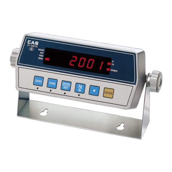
- Page 9 FRONT PANEL (CI-2001A) CAPACITY ZERO TARE GROSS STABLE CI- 2001A GROSS ZERO TARE PRINT ENTER 1. Display LAMP (■) lb Lamp ON when the weight unit is pound [lb] kg Lamp ON when the weight unit is kilogram [kg] STABLE ON when the weight is stable.
- Page 10 2. KEY PART Available keys instead of numeric keys. ▲, ◀ Change the set value ▲ Increase the first place value to 1 Change the digit of the set value Move to the left by 1 place ◀ USAGE : Input the numeral value in TEST, CAL, SET mode.
- Page 11 3. How to enter TEST mode □ Turn on the Power while pressing the "PRINT" key and SET mode starts. 4. How to enter SET mode □ Turn on the Power while pressing the "ENTER" key and SET mode starts. 5.
- Page 12 FRONT PANEL (CI-2001B) STABLE ZERO CAPACITY CI- 2001B GROSS ZERO TARE LIGHT PRINT 1. Display LAMP (■) ON when the weight unit is pound [lb] ON when the weight unit is kilogram [kg] ON when the weight is stable. ○ ZERO ON when the current weight is 0 kg(0 lb).
- Page 13 2. KEY PART Available keys instead of numeric keys. ▲, ◀ Change the set value ▲ Increase the first place value to 1 Change the digit of the set value Move to the left by 1 place ◀ USAGE : Input the numeral value in TEST, CAL, SET mode.
- Page 14 3. How to enter TEST mode □ Turn on the Power while pressing the "PRINT" key and SET mode starts. 4. How to enter SET mode □ Turn on the Power while pressing the "LIGHT" key and SET mode starts. 5.
- Page 15 REAR PANEL ■ Rear Pannel Description RS-232C Serial interface port.(Computer, printer ...) PORT LOADCELL Port for connecting load cell. Port for DC power. POWER ( DC 12V adaptor are available ) CAL S/W Used in calibration starts. ON/OFF Power ON/OFF switch.
- Page 16 INSTALLATION LoadCell Connection ■ Connect load cell connector to load cell port which is in the backside of indicator. ► Connection Method Ref. Each L/C manufacturer's or model's wire color could be different. In that case, please note the following diagram. ►...
- Page 17 Increase the first place set value to 1 ▲ Move to the left by 1 place of the set value. ◀ Initialize Setting value. Move into next menu. (CI-2001A) ENTER Move into next menu. (CI-2001B) LIGHT 3. TEST MENU (TEST 1 - TEST 5)
- Page 18 CI-2001A KEY CODE CI-2001B KEY CODE CODE CODE ZERO ZERO TARE TARE PRINT PRINT ENTER LIGHT TEST 2 ■ FUNCTION : DISPLAY TEST DISPLAY DESCRIPTION TEST 2 condition TEST 2 is performed automatically REF 1. Program is automatically shifted to menu selection mode after completing TEST 3 ■...
- Page 19 TEST 4 ■ FUNCTION : RS-232 TEST With Computer. DISPLAY DESCRIPTION ZERO : Transmit '0' TEST 4 condition TARE : Transmit '1' G/N : Transmit '2' Wait for transmission and reception kg/lb: Transmit '3' * : Transmit '4' Receive: 1, Transmit: none LIGHT: Next menu Receive: 1, Transmit: 13 REF 1.
- Page 20 ◀ PRINT (kg/lb version) Initial('0') of the set value. ‘*’ (kg only version)) ENTER Move into next menu. (CI-2001A) Move into next menu. (CI-2001B) LIGHT 3. CALIBRATION MENU (CAL 1 ~ CAL 5) CAL 1 Maximum Capacity CAL 2 Minimum Division...
- Page 21 CAL 1 ■ FUNCTION: SET Maximum Capacity Range → 1 ~ 999,999 kg (CI-2001A) 1 ~ 99,999 kg (CI-2001B) DISPLAY DESCRIPTION ▲: Increase of no. CAL 1 condition ◀: Shift of digit 100 kg/lb ENTER(LIGHT) : 10000 kg/lb Store and move into next menu REF 1.
- Page 22 CAL 3 ■ FUNCTION: Setting Weight In Span CALIBRATION Range → 1 ~ 999,999 kg (CI-2001A) 1 ~ 99,999 kg (CI-2001B) DISPLAY DESCRIPTION ▲: Increase of no. CAL 3 condition ◀: Shift of digit 100 kg ENTER(LIGHT) : Store and...
- Page 23 CAL 5 ■ FUNCTION: Span Calibration DISPLAY DESCRIPTION CAL 5 condition Load the weight which was set in ENTER(LIGHT) : CAL 3 and press LIGHT. Span calibration and Under span calibration. Move into next menu. Span calibration is completed. Press ENTER(LIGHT) key. (Save &...
- Page 24 Increase the first place set value to 1 ▲ Move to the left by 1 place of the set value. ◀ ENTER Move into next menu. (CI-2001A) LIGHT Move into next menu. (CI-2001B) 3. SET VALUE CONVERSION MENU (F01 - F19) Zero Key Operating Range (Only CI-2001B)
- Page 25 Digital Filter 1 : Less Vibration Adjust the set value according to the condition. 9: MuchVibration Weight Backup Weight back-up is off (Power on Zero) Weight back-up is on “PRINT” Key Usage (Only CI-2001A) No Use Total Print Key...
- Page 26 “ENTER” Key Usage (Only CI-2001A) No Use Total Print Key HOLD Key “*” Key Usage (Only CI-2001B) No Use Total Print Key HOLD Key Device ID 00 : Device ID ‘0’ It is used the ID of indicator when system is connected.
- Page 27 Output Mode No data output Stream Mode Transmit only in stable condition Transmit when data is required → Request signal : device ID (In case F10 : 1, Send Hex Value (F10 : Device ID) 01h in Computer) → In case F10 : 1, Send Hex Value 01h in Computer) Set Hold type Average hold : Compute the average weight of...
- Page 28 Line Feed 0 : No Line Feed Set Line Feed 9 : 9 Line Feed Set Model Select (Only CI-2001B) Set Model “CI-2001B” Set Model “CPS” Set Model “WCS” Set Auto Print (Only CI-2001B) No Use Auto Print Use Auto Print...
- Page 29 SERIAL INTERFACE Standard RS-232C Serial Interface ◈ RS-232C Port Connection ------------------------------ O 2 Transmit Data ------------------------------ O 3 Receive Data ------------------------------ O 7 Signal Ground ┌─ O 8 Carrier Detect ├─ O 20 Data Terminal Ready └─ O 6 Data Set Ready ┌─...
- Page 30 ◈ Data Format Data (8 bytes) CR LF └─┘ └─┘ └┐└────┐ ┏──┘ └─┘ US (Unstable) GS (Gross weight) Device ID Lamp Status byte Empty Unit (kg/t) ST (Stable) NT (Net weight) OL (Overload) ▣ Device ID Transmit 1 byte device ID so that the receiver can receive data selecti vely which indicator send.
- Page 31 *** C Language #include <bios.h> #include <conio.h> #define COM1 0 #define DATA_READY 0x100 #define TRUE 1 #define FALSE 0 #define SETTINGS 0xE3 int main(void) int in, out, status, DONE = FALSE; bioscom(0, SETTINGS, COM1); cprintf("... BIOSCOM [ESC] to exit ...\n"); while (!DONE) status = bioscom(3, 0, COM1);...
- Page 32 ◈ ND Series Serial Printer Connection ------------------------------ O 3 Transmit Data ------------------------------ O 2 Receive Data ------------------------------ O 5 Signal Ground 9 pin port (male) 9 pin port (female) RS-232C port of CI-20001 A/B ND Series Serial Printer Port Option RS-422/485 Serial Interface ▣...
- Page 33 ERROR MESSAGE (1) ERRORS IN WEIGHTING MODE Err 02 ▣ Reason Load cell connection failure or error in A/D conversion part. ☞ Trouble shooting Check the load cell connector to see if the polarity of signal is reversed. Err 06 ▣...
- Page 34 Err 10 ▣ Reason Tare weight exceeds the maximum capacity of the scale. ☞ Trouble shooting Set the tare to be smaller than the maximum capacity. Otherwise the maximum capacity is reset to be larger than the tare to be set in the calibration menu, and reset the calibration using weight.
- Page 35 (2) ERRORS IN CALIBRATION MODE Err 21 ▣ Reason The resolution is set to be exceeded the limit 1/10,000. ☞ Trouble shooting Lower the resolution. The resolution = allowed weight/one division Modify the allowed weight in CAL1 or modify the division in CAL2 so that the resolution should be below 1/10,000.
- Page 36 Err 24 ▣ Reason The load cell output is too small at SPAN calibration. ☞ Trouble shooting Setting of current resolution is not possible due to the error in load cell. Proceed calibration again with less resolution. Loadcell Sense Voltage Recommended Resolution for 5V Excitation Voltage 2 mV...
- Page 37 MEMO...
- Page 38 MEMO...
- Page 39 MEMO...
- Page 40 뒷표지...
Need help?
Do you have a question about the CI-2001A and is the answer not in the manual?
Questions and answers