Table of Contents

Related Manuals for Aerotech Ensemble QLe Series


Summary of Contents for Aerotech Ensemble QLe Series
-
Page 1: Ensemble Qle Hardware Manual
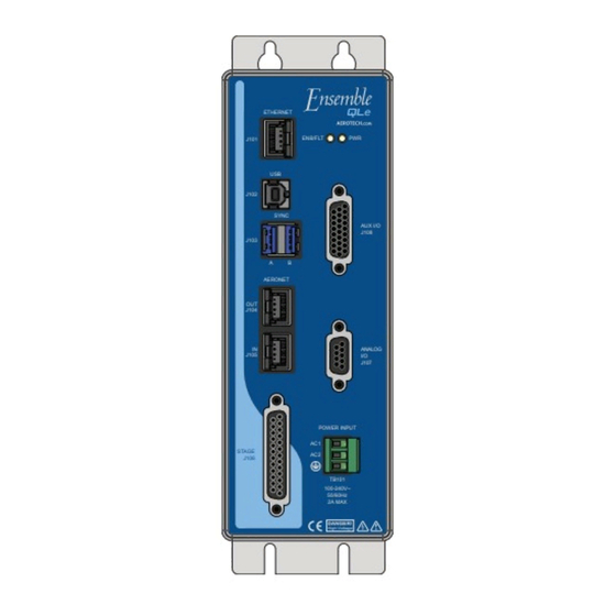
Ensemble QLe Hardware Manual Revision: 1.03.00 ETHERNET J101 ENB/FLT J102 SYNC AUX I/O J108 J103 AERONET J104 ANALOG J105 J107 POWER INPUT STAGE J106 TB101 100-240V~ 50/60Hz 2A MAX DANGER! High Voltage... - Page 2 This manual contains proprietary information and may not be reproduced, disclosed, or used in whole or in part without the express written permission of Aerotech, Inc. Product names mentioned herein are used for identification purposes only and may be trademarks of their respective companies.
-
Page 3: Table Of Contents
2.5.4. External Voltage Command 2.6. Communication 2.6.1. USB Interface 2.6.2. Ethernet Interface 2.6.3. Aeronet Interface 2.6.4. SYNC Interface 2.7. PC Configuration and Operation Information Chapter 3: Maintenance 3.1. Preventative Maintenance Appendix A: Warranty and Field Service Appendix B: Revision History Index www.aerotech.com... -
Page 4: List Of Figures
Inputs Connected in Current Sinking Mode (J108) Figure 2-8: High Speed User Inputs (J108) Figure 2-9: Analog Input 0 (J108) Figure 2-10: Analog Input 1 (J107) Figure 2-11: USB Connection Location Figure 2-12: Ethernet Connection Location Figure 2-13: Aeronet Connections Figure 2-14: Sync Interface www.aerotech.com... -
Page 5: List Of Tables
Voltage Monitor Output Specifications Table 2-25: External Voltage Command Connector Pin Assignment (J107) Table 2-26: External Voltage Command Scaling Table 2-27: External Voltage Command Specifications Table 2-28: Aeronet Cable Part Numbers Table 3-1: LED Description Table 3-2: Troubleshooting Table 3-3: Preventative Maintenance www.aerotech.com... - Page 6 Table of Contents Ensemble QLe Hardware Manual This page intentionally left blank. www.aerotech.com...
-
Page 7: Eu Declaration Of Conformity
Ensemble QLe Hardware Manual Declaration of Conformity EU Declaration of Conformity Manufacturer Aerotech, Inc. Address 101 Zeta Drive Pittsburgh, PA 15238-2811 Product Ensemble QLe Model/Types This is to certify that the aforementioned product is in accordance with the applicable requirements of the... -
Page 8: Agency Approvals
Declaration of Conformity Ensemble QLe Hardware Manual Agency Approvals Aerotech, Inc. Model Ensemble QLe Drives have been tested and found to be in accordance to the following listed Agency Approvals: Approval / Certification: CUS NRTL Approving Agency: TUV SUD America Inc. -
Page 9: Safety Procedures And Warnings
4. To avoid the risk of electric shock, do not touch the piezo stage while it is energized. 5. Make sure the system is properly grounded in accordance with local electrical safety requirements. 6. Operator safeguarding requirements must be addressed during final integration of the product. www.aerotech.com... - Page 10 Declaration of Conformity Ensemble QLe Hardware Manual This page intentionally left blank. www.aerotech.com...
-
Page 11: Quick Installation Guide
Quick Start Connections Topic Section Connect to J106 Refer to Section 2.3. Connect the Aeronet Refer to Section 2.6.3. Connect to TB101 Refer to Section 2.2.1. Connect to J107 Refer to Section 2.5. Connect to J108 Refer to Section 2.4. www.aerotech.com... - Page 12 Quick Installation Guide Ensemble QLe Hardware Manual This page intentionally left blank. www.aerotech.com...
-
Page 13: Chapter 1: Introduction
AUX I/O (J108) Connector ENB/FLT J101 ANALOG I/O (J107) Connector J102 SYNC AUX I/O J108 J103 POWER INPUT (TB101) AERONET ETHERNET (J101) J104 ANALOG J105 USB (J102) J107 SYNC (J103) POWER INPUT STAGE J106 AERONET TB101 OUT: J104 100-240V~ 50/60Hz 2A MAX IN: J105 DANGER! High Voltage STAGE (J106) Connector www.aerotech.com Chapter 1... -
Page 14: Table 1-1: Configuration And Options
-DYNAMIC CONTROLS The Dynamic Controls Toolbox provides control algorithms that increase TOOLBOX system performance such as settle time, accuracy, in-position stability and/or velocity stability. -LABVIEW LabVIEW® VI samples -MATLAB Includes MATLAB® library for motion, parameters, and data collection. Chapter 1 www.aerotech.com... -
Page 15: Figure 1-1: Functional Diagram
ETHERNET Ethernet Port Voltage Command J101 100Base-T Sensor Position SYNC Proprietary Bus J103 Flash Config STAGE J106 Logic Power Motor (+, -) Heatsink Over POWER Temperature Power INPUT Supply High Voltage TB101 Amplifier Figure 1-1: Functional Diagram www.aerotech.com Chapter 1... -
Page 16: Electrical Specifications
175 mA Warm Up Time 15 Minutes 15 Minutes Sensor Resolution 20-Bit (closed-loop) 20-Bit (closed-loop) Voltage Resolution 20-Bit (open-loop) 20-Bit (open-loop) High-Speed Data Capture 50 ns latency 50 ns latency Servo Loop Update 20 kHz 20 kHz Chapter 1 www.aerotech.com... -
Page 17: Mechanical Design
2A MAX DANGER! Drawing Number: 620E1421- High Voltage 2.3 [0.09] 4.8 [0.19] 157.5 [6.20] 4.5 [0.18] 66.3 [2.61] 73.8 [2.90] REC. MTG. HDWR.: M4 [#8] Figure 1-2: Dimensions Table 1-3: Physical Specifications Weight 1.3 kg [2.8 lbs] www.aerotech.com Chapter 1... -
Page 18: Environmental Specifications
Humidity Maximum relative humidity is 80% for temperatures up to 31°C. Decreasing linearly to 50% relative humidity at 40°C. Non condensing. Altitude Up to 2000 meters. Pollution Pollution degree 2 (normally only non-conductive pollution). Indoor use only. Chapter 1 www.aerotech.com... -
Page 19: Chapter 2: Installation And Configuration
QLe system is provided on the Serial and Power labels that are placed on the QLe chassis. The system serial number label contains important information such as the: Customer order number (please provide this number when requesting product support) Drawing number System part number www.aerotech.com Chapter 2... -
Page 20: Electrical Installation
(#16 AWG) 100 - 240 VAC Input Range 1.3 mm (#16 AWG) Protective Ground (Required for Safety) Screw Torque Wire Size: Type Aerotech P/N Phoenix P/N Value: Nm AWG [mm 3-Pin Terminal Block ECK00213 1754465 0.5 - 0.6 12-30 [3.3 - 0.516] Chapter 2 www.aerotech.com... -
Page 21: I/O And Signal Wiring Requirements
2. Insulation rating will need to be rated for the higher voltage if the wiring is in proximity to wiring operating at voltages above 60 V. 3. Larger gauge wire may be required to minimize voltage drop due to voltage (IR) loss in the cable. www.aerotech.com Chapter 2... -
Page 22: Stage Power And Feedback Connections (J106)
2. To avoid the risk of electric shock, do not touch the piezo stage while it is energized. The capacitance sensor interface is designed to work with Aerotech stages and cannot be used with third party sensors. The position feedback input signal (Pin 22) has a range of -10 to 10 VDC and can be connected to a third-party sensor with DC output. -
Page 23: Figure 2-2: Connection To Third Party Stage
Ensemble QLe Hardware Manual Installation and Configuration THIRD PARTY STAGE POSITION FEEDBACK (OPTIONAL) SIGNAL COMMON PIEZO ACTUATOR HIGH VOLTAGE OUTPUT (+) PIEZO PIEZO ACTUATOR RETURN (-) FRAME GROUND Figure 2-2: Connection to Third Party Stage www.aerotech.com Chapter 2... -
Page 24: Auxiliary I/O Connector (J108)
Opto-Isolated Input 2 Opto-Isolated Input 3 1. For PSO, see Section 2.4.1. Mating Connector Aerotech P/N Third Party P/N Connector ECK01259 Kycon K86-AA-26P Backshell ECK01022 Amphenol 17-1725-2 NOTE: These items are provided as a set under the Aerotech P/N: MCK-26HDD. Chapter 2 www.aerotech.com... -
Page 25: Position Synchronized Output (Pso)
Signals in excess of this rate will cause a loss of PSO accuracy. The optocoupler that you use on the output might have an effect on this rate. Table 2-6: PSO Output Pin Assignment (J108) Description Aux Marker - / PSO - Aux Marker + / PSO + Common www.aerotech.com Chapter 2... -
Page 26: Figure 2-3: Pso Interface
Isolated Section J108 10 mA 180 Ω Aux. Marker To Laser Active Low 1N4148 Output* HCPL-2601 or 6N136 * Active low output shown. Opposite polarity available by reversing connections to Pins 19 and 20. Figure 2-3: PSO Interface Chapter 2 www.aerotech.com... -
Page 27: Opto-Isolated Outputs
250 usec (2K pull up to 24V) Reset State Output Off (High Impedance State) Table 2-8: Digital Output Connector Pin Assignment (J108) Description Opto-Isolated Output 0 Opto-Isolated Output 1 Opto-Isolated Output 2 Common for Opto-Isolated Outputs 0-3 Opto-Isolated Output 3 www.aerotech.com Chapter 2... -
Page 28: Figure 2-4: Outputs Connected In Current Sourcing Mode (J108)
OPTOOUT0 J108-7 LOAD OPTOOUT1 J108-8 LOAD OPTOOUT2 J108-9 LOAD OPTOOUT3 J108-16 OPTOCOM J108-15 DIODE REQUIRED ON EACH OUTPUT THAT DRIVES AN INDUCTIVE DEVICE (COIL), SUCH AS A RELAY. Figure 2-5: Outputs Connected in Current Sinking Mode (J108) Chapter 2 www.aerotech.com... -
Page 29: Opto-Isolated Inputs
Turn On/Off Time 5 to 24 V 5 mA <100 usec Table 2-10: Digital Input Connector Pin Assignment (J108) Description Opto-Isolated Input 0 Opto-Isolated Input 1 Common for Opto-Isolated Inputs 0-3 Opto-Isolated Input 2 Opto-Isolated Input 3 www.aerotech.com Chapter 2... -
Page 30: Figure 2-6: Inputs Connected In Current Sourcing Mode (J108)
J108-26 OPTOINCOM J108-24 Figure 2-6: Inputs Connected in Current Sourcing Mode (J108) J108 OPTOINCOM J108-24 OPTOIN0 J108-17 5-24VDC OPTOIN1 J108-18 OPTOIN2 J108-25 OPTOIN3 J108-26 INPUT SWITCHES (Current Sinking) Figure 2-7: Inputs Connected in Current Sinking Mode (J108) Chapter 2 www.aerotech.com... -
Page 31: High-Speed User Inputs
High-Speed Digital Input Specifications Input Voltage Input Current Input Delay 5 to 24V 10 mA 50 ns OPTO5+ J108-5 CURRENT LIMITER OPTO5- J108-6 OPTO4+ HCPL-0630 CURRENT LIMITER J108-3 OPTO4- J108-4 Figure 2-8: High Speed User Inputs (J108) www.aerotech.com Chapter 2... -
Page 32: Analog Output
-10 V to +10 V Output Current 5 mA Resolution (bits) 16 bits Resolution (volts) 305 µV Refer to Section 2.5. for Analog Output 1. Table 2-14: Analog Output 0 Connector Pin Assignment (J108) Description Analog Output 0 Analog Common Chapter 2 www.aerotech.com... -
Page 33: Differential Analog Input
Analog Input 0 + (Differential) Analog Input 0 - (Differential) Analog Common +12V ANALOGIN0+ J108-13 Signal Shielded Source Cable ANALOGIN0- J108-14 ANALOG GND J108-23 -12V 1 Connection required for floating source. Figure 2-9: Analog Input 0 (J108) www.aerotech.com Chapter 2... -
Page 34: Analog I/O Connector (J107)
Analog Input 1+ Analog Input 1- Analog Output 1 External Voltage Command Piezo Voltage Monitor Analog Common Analog Common Analog Common Reserved Mating Connector Aerotech P/N 3rd Party P/N Backshell ECK01021 Amphenol DE24657 Connector ECK00340 Cinch DE-9S Chapter 2 www.aerotech.com... -
Page 35: Analog Output
Value Output Voltage -10 V to +10 V Output Current 5 mA (2 kΩ load) Resolution (bits) 20 bits Resolution (volts) 19 µV Table 2-19: Analog Output 1 Connector Pin Assignment (J107) Description Analog Output 1 Analog Common www.aerotech.com Chapter 2... -
Page 36: Figure 2-10: Analog Input 1 (J107)
Description Analog Input 1+ Analog Input 1- Analog Common +12V ANALOG IN- J107-2 Signal Shielded .001 Source Cable ANALOG IN+ J107-1 100PF 100PF J107-6 1 Connection required for floating source. -12V Figure 2-10: Analog Input 1 (J107) Chapter 2 www.aerotech.com... -
Page 37: Voltage Monitor Output
Piezo Voltage Monitor Analog Common Table 2-23: Voltage Monitor Output Scaling Piezo Voltage Voltage Monitor +150 V +10 V 0 V -30 V -2 V Table 2-24: Voltage Monitor Output Specifications Description Accuracy ±3.5% Nominal Recommended Load ≥10k Ω www.aerotech.com Chapter 2... -
Page 38: External Voltage Command
Table 2-26: External Voltage Command Scaling External Voltage Command (Input) Piezo Voltage (Output) +10 V +150 V 0 V -2 V -30 V Table 2-27: External Voltage Command Specifications Description Input Range -2V to +10V Input Impedance 20k Ω Chapter 2 www.aerotech.com... -
Page 39: Communication
USB ports on the PC. J102 ETHERNET J101 ENB/FLT J102 SYNC AUX I/O J108 J103 AERONET J104 ANALOG J105 J107 POWER INPUT STAGE J106 TB101 100-240V~ 50/60Hz 2A MAX DANGER! High Voltage Figure 2-11: USB Connection Location www.aerotech.com Chapter 2... -
Page 40: Ethernet Interface
PC. This type of connection is not feasible unless the PC has two Ethernet cards. If the PC cannot be connected to an external network, Aerotech recommends Method 2. Method 2 is a more typical configuration. The network can be a local network (the PC and QLe are connected through a hub or switch) or remote (the devices are connected through a router). -
Page 41: Aeronet Interface
A CAT6 cable; length is 30 decimeters ENET-CAT6-45 A CAT6 cable; length is 45 decimeters ENET-CAT6-76 A CAT6 cable; length is 76 decimeters ENET-CAT6-90 A CAT6 cable; length is 90 decimeters Cable lengths are in decimeters, 10dm = 1 meter = 3.28 feet www.aerotech.com Chapter 2... -
Page 42: Sync Interface
The Sync connection contains a proprietary bus which is currently reserved for future expansion. SYNC J103 ETHERNET ENB/FLT J101 J102 SYNC AUX I/O J108 J103 AERONET J104 ANALOG J105 J107 POWER INPUT STAGE J106 TB101 100-240V~ 50/60Hz 2A MAX DANGER! High Voltage Figure 2-14: Sync Interface Chapter 2 www.aerotech.com... -
Page 43: Pc Configuration And Operation Information
Ensemble QLe Hardware Manual Installation and Configuration 2.7. PC Configuration and Operation Information For additional information about PC configuration, hardware requirements, programming, utilities, and system operation refer to the Help file. www.aerotech.com Chapter 2... - Page 44 Installation and Configuration Ensemble QLe Hardware Manual This page intentionally left blank. Chapter 2 www.aerotech.com...
-
Page 45: Chapter 3: Maintenance
There is no reason to remove the cover or access the internal components. The QLe does not have any user- configurable switches or jumpers. Internal fuses are not user-replaceable. N O T E : Having to replace a fuse indicates a more serious problem with the system or setup; consult Aerotech for assistance. Table 3-1: LED Description Description Turns green when power is applied. -
Page 46: Preventative Maintenance
The electrical power must be disconnected from the Ensemble QLe while cleaning. Do not allow cleaning substances or other fluids to enter the Ensemble QLe or to get on to any of the connectors. Avoid cleaning labels to prevent removing the label information. Chapter 3 www.aerotech.com... -
Page 47: Appendix A: Warranty And Field Service
Aerotech makes no warranty that its products are fit for the use or purpose to which they may be put by the buyer, whether or not such use or purpose has been disclosed to Aerotech in specifications or drawings previously or subsequently provided, or whether or not Aerotech’s... - Page 48 Aerotech's approval. On-site Warranty Repair If an Aerotech product cannot be made functional by telephone assistance or by sending and having the customer install replacement parts, and cannot be returned to the Aerotech service center for repair, and if Aerotech determines the problem could be warranty-related, then the following policy applies:...
-
Page 49: Appendix B: Revision History
Section 2.4.1. Position Synchronized Output (PSO) Section 2.4.2. Opto-Isolated Outputs 0-3 Section 2.4.3. Opto-Isolated Inputs 0-3 Section 2.4.5. Analog Output 0 Section 2.4.6. Differential Analog Input 0 Section 2.5.1. Analog Output 1 Section 2.5.2. Differential Analog Input 1 1.00.00 New manual www.aerotech.com Appendix B... - Page 50 Revision History Ensemble QLe Hardware Manual This page intentionally left blank. Appendix B www.aerotech.com...
-
Page 51: Index
Electrical Specifications Sensor Resolution Environmental Specifications Servo Loop Update shipping damage Functional Diagram Support fuse Technical Support Global Technical Support unit weight High-Speed Data Capture Humidity Voltage Resolution Input Frequency Input Power Warm Up Time Input Voltage inspect www.aerotech.com Index... - Page 52 Index Ensemble QLe Hardware Manual This page intentionally left blank. Index www.aerotech.com...
Need help?
Do you have a question about the Ensemble QLe Series and is the answer not in the manual?
Questions and answers