
Subscribe to Our Youtube Channel
Related Manuals for SUTO S450


Summary of Contents for SUTO S450
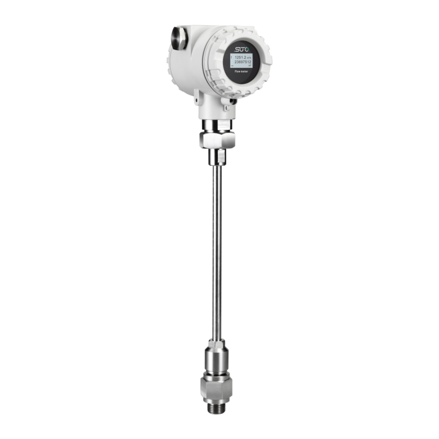
- Page 1 English Instruction and Operation Manual S450 Thermal Mass Flow Meter for Heavy Duty and Ex Applications (Insertion)
- Page 2 The device is destined exclusively for the described application. SUTO offers no guarantee for the suitability for any other purpose. SUTO is also not liable for consequential damage resulting from the delivery, capability or use of this device.
-
Page 3: Table Of Contents
9.1.1 Analog output...............21 9.1.2 Pulse output..............21 9.2 HART output ..............22 9.3 Modbus Interface ..............23 9.4 M-Bus output ..............26 9.5 Connection between S450 Outputs and Customer Equipment..26 10 Information on the Display............29 10.1 Startup................29 10.2 Data and Signs..............30 11 Configuration................31 12 Optional accessories..............34 12.1 Display................34... -
Page 4: Safety Instructions
• Consider all regulations for electrical installations. • The system must be disconnected from any power supply during maintenance work. • Any electrical work on the system is only allowed by authorized qualified personal. S450... - Page 5 • Always observe the direction of the flow when installing the flow meter. The direction is indicated on the housing. • Do not exceed the maximum operation temperature at the sensors tip. • Avoid condensation on the sensor element as this will affect the accuracy enormously. S450...
-
Page 6: Registered Trademarks
• Avoid direct UV and solar radiation during storage. • For the storage the humidity must be <90% with no condensation. 2 Registered trademarks ® SUTO Registered trademark of SUTO iTEC ® MODBUS Registered trademark of the Modbus Organization, Hopkinton, USA Android™,... -
Page 7: Application
3 Application 3 Application The S450 Thermal Mass Flow Meter is designed for the explosive areas and is mainly used to measure compressed air and process gases in industrial environments. The S450 can measure the following parameters for the compressed air or gases: •... -
Page 8: Technical Data
Note: For pressure above 1.5 MPa you need to use the installation device A530 1106 or A530 1113. Housing material Al alloy Material of the probe Stainless steel 1.4404 (SUS 316L) tube, sensor head and screwing Protection class IP67 S450... -
Page 9: Electrical Data
±(1.5% of reading + 0.3% full scale) Repeatability 0.25% of reading Stated accuracy at Ambient/process temperature 23°C±3°C Ambient/process humidity <90% Process pressure at 0.6 MPa * The specified accuracy is valid only within the minimum and maximum flow rates that are stated in section 5.5. S450... -
Page 10: Flow Ranges
• To calculate flow ranges based on pipe and reference conditions in your site, download and install the "Flow range calculator" tool for free from http://www.suto-itec.com. • To fast access the tool download page, enter "flowrange" (without spaces) in the search field, and click the tool in the search result. -
Page 11: Dimensional Drawing
6 Dimensional drawing 6 Dimensional drawing S450... -
Page 12: Determine The Installation Point
Obstructions can cause counter-flow turbulence as well as turbulence in the direction of the flow. • It is strongly recommend not to install S450 permanently in wet environment which exists usually right after a compressor outlet. 7.1 Inlet and outlet sections The following figures show the necessary equalizing sections in relation to existing obstructions. - Page 13 7 Determine the installation point 90° Bend 2×90° Bend 3 dimensional Bend T-piece Shut-off valve Filter or similar (unknown objects) S450...
-
Page 14: Installation
1106 or A530 1113. Order No. Description A530 1106 High pressure installation device S450, 200 mm. To be used if pressure above 1.5 MPa. A530 1113 High pressure installation device S450, 400 mm. To be used if pressure above 1.5 MPa. -
Page 15: Installation Requirements
8.2.1 Determine the insertion depth The probe tip must be placed in the center of the pipe. For this the probe shaft has a scale. To determine the right position please calculate the insertion depth as described below. S450... -
Page 16: Install The Flow Meter
First please observe the flow direction indicated on the shaft. It must match the flow direction of the compressed air or gas. 1. Close the ball valve. 2. The probe tip must be be completely covered by the connection head (see photo on the left). S450... - Page 17 10. Tighten the clamp sleeve with the clamping torque 20 … 30 Nm. 11. Check the installation depth again because sometimes the shaft is moved from its original position by the compressed air. Maximum angle deviation of a proper installation: S450...
-
Page 18: Removing The Flow Meter
• Unused cable entries must be closed with closers. • Cable outer diameter should be between 6 and 8 mm. • Single wire cross-section should be between 0.25 ... 0.75 mm • The thread size for the cable glands is M20 / 1.5. S450... -
Page 19: Connection Diagram
8 Installation 8.3.1 Connection diagram Remove the back cover from the S450, and the pin layout is shown below. 8.3.2 Pin assignment The S450 provides four output options. The pin assignment of these options are given in the following table. - Page 20 Positive supply voltage Modbus data+ Negative supply voltage Modbus data - Positive signal output (analog M-Bus data output 1) Negative signal output (analog Not applicable output 1) Positive signal output (analog output 2) Negative signal output (analog output 2) S450...
-
Page 21: Signal Outputs
9 Signal outputs 9 Signal outputs 9.1 Analog and pulse outputs If the S450 is purchased with the output option of analog and pulse signals, it provides 2 analog outputs and 1 pulse output. All signals are electrically isolated. 9.1.1 Analog output The analog output can be used as an active output (current is sourced through the positive connection pin) or passive output. -
Page 22: Hart Output
If the S450 is purchased with the output option of HART, the HART signal is modulated on analog output 1. In case S450 is used in a multi- drop configuration (more than 1 slave on the 4-20 mA line) the analogue output can not be used anymore. -
Page 23: Modbus Interface
The Modbus communication requires to activate terminal resistors at the last device on the bus system. If the S450 is the last device on the bus system, the DIP switches on the connector board should be set to “ON”... - Page 24 Byte3-Byte2, is received from the slave (sensor), the master must change the byte order to Byte0-Byte1-Byte2-Byte3 for the correct display of the value. Remarks: Modbus communication settings as well as other settings can be changed by the service App or through the windows based Service Software. S450...
- Page 25 9 Signal outputs Available measurement channels: Modbus Channel description Unit Resolution Format Length Register address Velocity FLOAT 4-Byte Flow FLOAT 4-Byte Consumption UNIT32 4-Byte Reverse consumption UNIT32 4-Byte Medium temperature FLOAT 4-Byte °C Ambient temperature FLOAT 4-Byte °C S450...
-
Page 26: M-Bus Output
9 Signal outputs 9.4 M-Bus output If the S450 is purchased with the output option of M-Bus, it provides one analog output and one pulse output besides the M-Bus output. Device type : Slave Address range : 1 to 251... - Page 27 9 Signal outputs Modbus/RTU output M-Bus output HART output Active HART output Note:The active HART output can only support one HART slave. S450...
- Page 28 9 Signal outputs Passive HART output Note: If you want to connect multiple slaves on the bus (multidrop), use the passive solution. S450...
-
Page 29: Information On The Display
10 Information on the Display 10 Information on the Display When the S450 comes with a display, startup information, measuring values, and more can be viewed on the display. 10.1 Startup Software and hardware versions Online measuring values: flow and consumption. -
Page 30: Data And Signs
10 Information on the Display 10.2 Data and Signs This section explains data and signs on the display when the S450 goes into a normal working state. Flow value, 6 digits Flow unit Consumption value, 10 digit Consumption unit Flow direction sign. -
Page 31: Configuration
11 Configuration 11 Configuration S450 enables you to configure parameter settings according to on-site requirements. The table below gives an overview about the available settings. Parameters Available settings Default Measurement Tube diameter 54.0 Flow unit Consumption unit Reference conditions = 1000 hPA = 20°C... - Page 32 Remark: To enable a stable Bluetooth communication, ensure the following: • Distance between the S450 and the PC must be not more than 5 meters. • The PC Bluetooth antenna must point roughly at the direction of the display (front part).
- Page 33 11 Configuration S450...
-
Page 34: Optional Accessories
PC and an S450. The diagram below shows the cable connection between an S450 and a PC through the service kit. Please ensure that S450 or the service kit is connected with the power supply because the USB port cannot provide enough power to both of them. -
Page 35: Calibration
The device, the accessories and its packings must be disposed according to your local statutory requirements. The dispose can also be carried by the manufacturer of the product. Please contact the manufacturer for details. S450... - Page 36 SUTO iTEC GmbH SUTO iTEC (ASIA) Co., Ltd. Grißheimer Weg 21 Room 10, 6/F, Block B, Cambridge Plaza D-79423 Heitersheim 188 San Wan Road, Sheung Shui, N.T. Germany Hong Kong Tel: +49 (0) 7634 50488 00 Tel: +852 2328 9782 Email: sales@suto-itec.com...
Need help?
Do you have a question about the S450 and is the answer not in the manual?
Questions and answers