Bender ISOMETER isoPV425 Manual
Insulation monitoring device for unearthed dc circuits (it systems) for photovoltaic systems up to 3(n)ac, ac 690 v / dc 1000 v
Hide thumbs
Also See for ISOMETER isoPV425:
- Manual (68 pages) ,
- Quick star manual (9 pages) ,
- Manual (60 pages)

Related Manuals for Bender ISOMETER isoPV425


Summary of Contents for Bender ISOMETER isoPV425
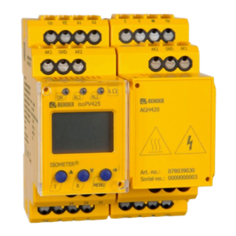
- Page 1 Manual EN ISOMETER® isoPV425 with AGH420 coupling device Insulation monitoring device for unearthed DC circuits (IT systems) for photovoltaic systems up to 3(N)AC, AC 690 V / DC 1000 V isoPV425_D00028_11_M_XXEN/07.2023...
- Page 2 isoPV425_D00028_11_M_XXEN/07.2023...
-
Page 3: Table Of Contents
Indication of important instructions and information...............5 Signs and symbols............................5 Service and Support............................5 Training courses and seminars........................5 Delivery conditions............................6 Inspection, transport and storage......................6 Warranty and liability.............................6 Disposal of Bender devices..........................6 1.10 Safety..................................7 Function.......................8 Intended use..............................8 Device features..............................8 Functional description........................... 9 2.3.1... - Page 4 Table of contents Menu overview...............................20 Displaying measured values........................20 Setting the response values (AL)......................21 4.4.1 Setting the insulation resistance parameters..................21 4.4.2 Setting parameters for undervoltage and overvoltage..............22 4.4.3 Response values overview.........................22 Configuring fault memory, alarm relays, and interfaces (out)............22 4.5.1 Configuring the relays..........................22 4.5.2...
-
Page 5: General Information
Recycling RoHS directives Service and Support Information and contact details about customer service, repair service or field service for Bender devices are available on the following website: Fast assistance | Bender GmbH & Co. KG. Training courses and seminars Regular face-to-face or online seminars for customers and other interested parties: www.bender.de >... -
Page 6: Delivery Conditions
General information Delivery conditions The conditions of sale and delivery set out by Bender GmbH & Co. KG apply. These can be obtained in printed or electronic format. The following applies to software products: ‘Software clause in respect of the licensing of standard software as part of deliveries,... -
Page 7: Safety
ISOMETER® isoPV425 with AGH420 coupling device 1.10 Safety If the device is used outside the Federal Republic of Germany, the applicable local standards and regulations must be complied with. In Europe, the European standard EN 50110 applies. DANGER Risk of fatal injury due to electric shock! Touching live parts of the system carries the risk of: •... -
Page 8: Function
• Fault memory can be activated • Password protection against unauthorised changing of parameters • RS-485 (galvanically isolated) including the following protocols: – BMS (Bender measuring device interface) for the data exchange with other Bender devices – Modbus RTU – IsoData (for continuous data output) -
Page 9: Functional Description
ISOMETER® isoPV425 with AGH420 coupling device Functional description The ISOMETER® measures the insulation resistance R and the system leakage capacitance C between the system to be monitored (L1/+, L2/–) and earth (PE). The RMS value of the nominal system voltage U between L1/+ and L2/–... -
Page 10: Undervoltage/Overvoltage Monitoring
Function 2.3.2 Undervoltage/overvoltage monitoring The two parameters ('U ˂' and 'U ˃') used to monitor the nominal system voltage U can be enabled or disabled in the response-value menu 'AL' (chapter 4.4). The maximum undervoltage value is limited by the overvoltage value. -
Page 11: Malfunction
('err') will be signalled, 'E.xx' appears on the display as an identifier for error type xx, and the LEDs 'ON'/'AL1'/'AL2' will flash. Please contact Bender Service, if the error occurs again after the device has been restarted or the factory settings have been restored. -
Page 12: Measuring And Response Times
Function Recommendation: Set parameter value 'S.AL' identical for both relays. 2.3.6 Measuring and response times Operating time t The operating time t is the time required by the ISOMETER® to determine the measured value. For the insulation measured value R , the system leakage capacitance C , the residual voltages U and U... -
Page 13: Fault Memory
The ISOMETER® uses the serial hardware interface RS-485 with the following protocols: • BMS The BMS protocol is an essential component of the Bender measuring device interface (BMS bus protocol). Data transmission generally makes use of ASCII characters. • Modbus RTU Modbus RTU is an application layer messaging protocol, and it provides master/slave communication between devices that are connected via bus systems and networks. -
Page 14: Installation, Connection And Commissioning
Installation, connection and commissioning Installation, connection and commissioning Dimensions 45 70.5 31.1 47.5 74.5 Figure: Dimension diagram (in mm) Installation Figure: DIN rail mounting (left) or screw mounting (right) isoPV425_D00028_11_M_XXEN/07.2023... -
Page 15: Connection
ISOMETER® isoPV425 with AGH420 coupling device Connection For details about the required conductor cross sections, refer to the technical data from Technical data isoPV425. Figure: Wiring diagram CAUTION Danger from touching hot surfaces! If the AGH420 is operated at mains voltages > 800 V, the temperature of the enclosure may exceed 60 °C. •... -
Page 16: Commissioning
Installation, connection and commissioning Wiring diagram legend: Terminal Connections Connection to the supply voltage U via a fuse: A1, A2 If supplied from an IT system, both lines have to be protected by a fuse.* Connect each terminal separately to PE: E, E, KE Use the same wire cross section as for 'A1', 'A2'. - Page 17 ISOMETER® isoPV425 with AGH420 coupling device The list of factory settings is shown in the tables from chapter 4.4. Check the function using a genuine insulation fault. Check the ISOMETER® against earth in the system being monitored, e.g. via a suitable resistance. isoPV425_D00028_11_M_XXEN/07.2023...
-
Page 18: Operation
Operation Operation Operating and display elements Device front Operating elements Function Device is running Prewarning Overvoltage Alarm Undervoltage Up and down buttons – For navigating up or down in the menu settings. – For increasing or decreasing values. Test button (press > 1.5 s) Reset button (press >... - Page 19 ISOMETER® isoPV425 with AGH420 coupling device Display Display elements Function Nominal system voltage U Amperage I Insulation resistance R Impedance Z System leakage capacitance C Monitored conductors L1 L2 Voltage type DC Pulse symbol: error-free measured value update Voltage type AC auto Automatic self test active °C...
-
Page 20: Menu Overview
Operation Menu overview Measurement display Menu selection Parameter selection Menu item Parameter Querying and setting response values Configuring fault memory, alarm relays and interface Setting delay times and self test cycles Setting device control parameters Querying software version Querying and clearing the history memory Going to the next-higher menu level Displaying measured values Overview... -
Page 21: Setting The Response Values (Al)
ISOMETER® isoPV425 with AGH420 coupling device Display Description ✓ Nominal system voltage L1 - L2 ~ ± U L1 L2 V …1.2 kV Resolution 1 V / 10 V Residual voltage L1/+ - PE ✓ ± U L1 … ±1.2 kV Resolution 1 V / 10 V Residual voltage L2/–... -
Page 22: Setting Parameters For Undervoltage And Overvoltage
Operation 4.4.2 Setting parameters for undervoltage and overvoltage How to proceed Open menu 'AL'. Select parameter 'U <' for undervoltage or parameter 'U >' for overvoltage. Set value and confirm with Enter. 4.4.3 Response values overview Display Activation Setting value Description Range Prewarning value R... -
Page 23: Allocating Messages To The Relays
ISOMETER® isoPV425 with AGH420 coupling device 4.5.2 Allocating messages to the relays The 'on' setting allocates a message to the corresponding relay. The LED indication is directly assigned to the alarms and is not related to the relays. If the device can assign an asymmetrical insulation fault to the corresponding conductor (L1/+ or L2/–), it will only signal the respective alarm. -
Page 24: Configuring Interfaces
Operation 4.5.4 Configuring interfaces Display Setting value Description Range Adr = 0 deactivates BMS as well as Modbus 0/3…90 Bus Adr. and activates isoData with continuous data output (115k2, 8E1) ---/ '---': BMS bus (9k6, 7E1) Adr 1 '---' ) Baud rate 1.2 k…115 k '1.2k' …... -
Page 25: Reset To Factory Settings
Test of the system connection during device test S.Ct Device test during device start Restore factory settings For Bender Service only FAC Factory settings Customer settings Reset to factory settings All settings with the exception of the interface parameters are reset to the factory settings. -
Page 26: Data Access Via Interfaces
Data access via interfaces Data access via interfaces Data access using the BMS protocol The BMS protocol is an essential component of the Bender measuring device interface (BMS bus protocol). Data transmission generally makes use of ASCII characters. BMS channel no. -
Page 27: Data Access Using The Modbus Rtu Protocol
ISOMETER® isoPV425 with AGH420 coupling device String Beschreibung 1234, 5; Reserved Nominal system voltageU +1234; Nominal system voltage type: AC or unknown: ' ' | DC: '+' / '–' Residual voltage U +1234; Residual voltage U +1234; +123; Insulation fault location –100 … +100 [%] Genäherter unsymmetrischer Isolationswiderstand R [k ] 1234, 5;... -
Page 28: Writing The Modbus Register (Parameter Setting)
Data access via interfaces Command of the master to the ISOMETER® In the following example, the master of the ISOMETER® requests the content of register 1003 using address 3. The register contains the channel description of measuring channel 1. Byte Name Example Byte 0... -
Page 29: Exception Code
ISOMETER® isoPV425 with AGH420 coupling device The ISOMETER® answers the master Byte Name Example Byte 0 ISOMETER® Modbus address 0x03 Byte 1 Function code 0x10 Byte 2, 3 Start register 0x0BBB Byte 4, 5 Number of registers 0x0001 Byte 6, 7 CRC16 checksum 0x722A 5.3.3... -
Page 30: Modbus Register Assignment
Data access via interfaces 5.3.4 Modbus register assignment Depending on the device status, the information in the registers is either: the measured value without alarm; the measured value with alarm 1; the measured value with alarm 2; or only the device fault. For more information see 'AT&T = Alarm type and test type (internal/external)'. - Page 31 ISOMETER® isoPV425 with AGH420 coupling device Register Property Description Format Unit Value range Pre-alarm value 3005 resistance UINT 16 R2…500 measurement 'R1' 3006 Reserved Alarm value resistance 3007 UINT 16 1…R1 measurement 'R2' Activation alarm value 0 = Inactive 3008 UINT 16 undervoltage 'U <' 1 = Active...
- Page 32 Data access via interfaces Register Property Description Format Unit Value range Delay on release 'toff' 3020 UINT 16 0 … 99 for relays 'K1' and 'K2' 0 = OFF Repetition time 3021 'test' for automatic UINT 16 1 = 1 h device test 2 = 24 h 3022...
-
Page 33: Device-Specific Data Types
ISOMETER® isoPV425 with AGH420 coupling device Register Property Description Format Unit Value range 9825 Modbus driver version UINT 16 RO Read only RW Read/Write WO Write only 5.3.5 Device-specific data types Device name The data format of the device name consists of ten Words with two ASCII characters each. 0x00 0x01 0x02... - Page 34 Data access via interfaces AT&T = Alarm type and test type (internal/external) Meaning Test Test Reserved Reserved Reserved Alarm Fault external internal Alarm No alarm type Prewarning Device error Reserved Warning Alarm Reserved Reserved Test No test Internal test External test •...
- Page 35 ISOMETER® isoPV425 with AGH420 coupling device R&U = Range and unit Meaning Unit Invalid (init) No unit Baud °C °F Second Minute Hour Month Range of validity Actual value The actual value is lower The actual value is higher Invalid value •...
- Page 36 Data access via interfaces Alarm assignment of the relays Several alarms can be assigned to each relay. For the assignment to each relay, a 16-bit register is used with the bits described below. The following table applies to relay 1 and relay 2, in which 'x' stands for the relay number. A set bit activates the specified function.
- Page 37 ISOMETER® isoPV425 with AGH420 coupling device Channel descriptions Value Description of measured value / message Comments 1 (0x01) Insulation fault 71 (0x47) Insulation fault Insulation resistance R 76 (0x4C) Voltage Measured value in V 77 (0x4D) Undervoltage 78 (0x4E) Overvoltage 82 (0x52) Capacitance Measured value in F...
- Page 38 Data access via interfaces Value Description of parameters 1010 (0x3F2) Time 1009 (0x3F1) Operator multiplication [*] 1008 (0x3F0) Operator division [/] 1007 (0x3EF) Baud rate isoPV425_D00028_11_M_XXEN/07.2023...
-
Page 39: Technical Data
ISOMETER® isoPV425 with AGH420 coupling device Technical data Technical data isoPV425 Insulation coordination acc. to IEC 60664-1/IEC 60664-3 Definitions Supply circuit (IC2) A1, A2 Output circuit (IC3) 11, 14, 24 Control circuit (IC4) E, KE, T/R, A, B, AK1, GND, AK2 Rated voltage 240 V Overvoltage category... - Page 40 Technical data IT system being monitored Nominal system voltage U withAGH420 3(N)AC, AC 0…690 V / DC 0…1000 V Tolerance of U AC +15 %, DC +10 % Nominal system voltage range U with AGH420 (UL508) AC/DC 0…600 V Frequency range of U DC, 15…460 Hz Measuring circuit Permissible system leakage capacitance C...
- Page 41 ISOMETER® isoPV425 with AGH420 coupling device Display range measured value nominal system voltage (U 30…1150 V Operating uncertainty ±5 %, at least ±5 V Relative uncertainty depending on the frequency ≥ 200 Hz –0,03 %/Hz Display range measured value system leakage capacitance at R >...
- Page 42 Technical data Environment/EMC IEC 61326-2-4 Ambient temperatures Operation –40…+70 ºC Transport –40…+85 ºC Storage –40…+70 ºC Classification of climatic conditions acc. to IEC 60721(related to temperature and relative humidity) Stationary use (IEC 60721-3-3) 3K22 Transport (IEC 60721-3-2) 2K11 Long-term storage (IEC 60721-3-1) 1K22 Classification of mechanical conditions acc.
-
Page 43: Technical Data Agh420
ISOMETER® isoPV425 with AGH420 coupling device Push-wire terminals Nominal current ≤ 10 A Conductor sizes AWG 24-14 Stripping length 10 mm Rigid 0.2…2.5 mm Flexible without ferrules 0.75…2.5 mm Flexible with ferrules with/without plastic sleeve 0.25…2.5 mm Multi-conductor flexible with TWIN ferrules with plastic sleeve 0.5…1.5 mm Opening force 50 N... - Page 44 Technical data Rated insulated voltage IC1/IC2 1000 V Polution degree Protective separation (reinforced insulation) between IC1/IC2 Overvoltage category III, 1000 V Monitored IT system Nominal system voltage range U AC/DC 0…1000 V Tolerance of U AC/DC +10 % Nominal system voltage range U (UL508) AC/DC 0…600 V Measuring circuit...
- Page 45 ISOMETER® isoPV425 with AGH420 coupling device Connection Screw-type terminals Nominal current ≤ 10 A Tightening torque 0.5…0.6 Nm (5…7 lb-in) Conductor sizes AWG 24-12 Stripping length 8 mm Rigid/flexible 0.2…2.5 mm Flexible with ferrules with/without plastic sleeve 0.25…2.5 mm Multi-conductor rigid 0.2…1.5 mm Multi-conductor flexible 0.2…1.5 mm...
-
Page 46: Standards And Certifications
EU Declaration of Conformity Hereby, Bender GmbH & Co. KG declares that the device covered by the Radio Directive complies with Directive 2014/53/EU. The full text of the EU Declaration of Conformity is available at the following Internet address: https://www.bender.de/fileadmin/content/Products/CE/CEKO_isoXX425.pdf... - Page 47 ISOMETER® isoPV425 with AGH420 coupling device Suitable system components Description Type Article number AGH420 Coupling device for ISOMETER® isoPV425 or isoEV425 B78039030 Supply voltage: AC 0...690 V/DC 0...1000 V B98039030 Push-wire terminal version Screw-type terminal version isoPV425_D00028_11_M_XXEN/07.2023...
- Page 48 Alle Rechte vorbehalten. 35305 Grünberg Nachdruck und Vervielfältigung nur mit Germany Genehmigung des Herausgebers. © Bender GmbH & Co. KG, Germany Subject to change! The specified Tel.: +49 6401 807-0 All rights reserved. standards take into account the edition info@bender.de Reprinting and duplicating only with valid until 07.2023 unless otherwise...
Need help?
Do you have a question about the ISOMETER isoPV425 and is the answer not in the manual?
Questions and answers