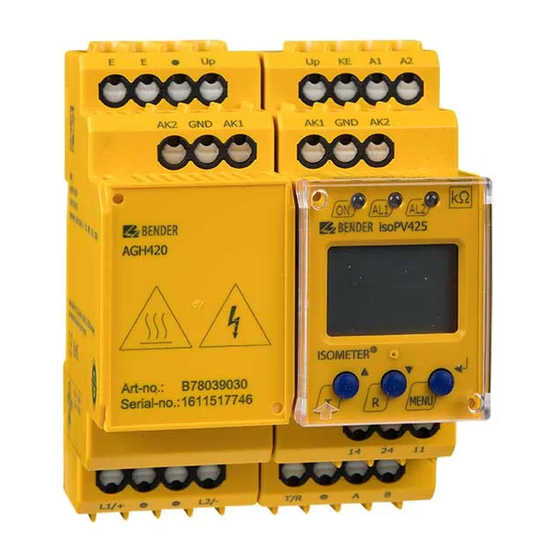
Bender ISOMETER isoPV425 with AGH420 Manual
Insulation monitoring device for unearthed it ac, ac/dc and dc systems for photovoltaic systems up to ac 690 v / dc 1000 v
Hide thumbs
Also See for ISOMETER isoPV425 with AGH420:
- Manual (68 pages) ,
- Quick star manual (9 pages) ,
- Manual (48 pages)
Table of Contents

Related Manuals for Bender ISOMETER isoPV425 with AGH420


Summary of Contents for Bender ISOMETER isoPV425 with AGH420
- Page 1 Manual ISOMETER® isoPV425 with AGH420 coupling device Insulation monitoring device for unearthed IT AC, AC/DC and DC systems for photovoltaic systems up to AC 690 V / DC 1000 V Software version: D404 V1.0x isoPV425_D00028_02_M_XXEN/09.2014...
- Page 2 Bender GmbH & Co. KG Londorfer Str. 65 • 35305 Gruenberg • Germany Postfach 1161 • 35301 Gruenberg • Germany Tel.: +49 6401 807-0 Fax: +49 6401 807-259 E-Mail: info@bender.de Web: http://www.bender.de http://www.bender-emobility.com © Bender GmbH & Co. KG All rights reserved.
-
Page 3: Table Of Contents
Table of Contents 1. Making effective use of this document ............5 How to use this manual ................. 5 Information about factory setting ............. 6 2. Safety instructions ................... 7 General safety instructions ................7 Work activities on electrical installations ..........7 High surface temperature due to operational conditions .... - Page 4 Table of Contents 4. Installation, connection and commissioning ........... 15 Installation ....................... 15 Connection ...................... 17 Commissioning ....................20 5. Operation and configuration ..............21 Factory setting ....................21 Getting to know the user interface ............22 Understand information on the display ..........23 5.3.1 Querying measured values ................
-
Page 5: Making Effective Use Of This Document
1. Making effective use of this document 1.1 How to use this manual This manual is intended for electrically skilled persons working in electrical engineering and electronics! To make it easier for you to understand and revisit certain sections of text and instructions in the manual, we have used symbols to identify important in- structions and information. -
Page 6: Information About Factory Setting
Making effective use of this document 1.2 Information about factory setting Page 21 provides a summary of all factory settings. If you want to reset the ISOMETER® to its factory setting in a specific case, refer to page 44. isoPV425_D00028_02_M_XXEN/09.2014... -
Page 7: Safety Instructions
2.1 General safety instructions In addition to these operating instructions, the "Important safety instructions for Bender products“, which are also included in the scope of supply, are an integral part of the device documentation. 2.2 Work activities on electrical installations... -
Page 8: High Surface Temperature Due To Operational Conditions
Safety instructions 2.3 High surface temperature due to operational conditions Danger from touching hot surfaces! If the AGH420 is operated at system voltages > 800 V, the temperature of the enclosure may exceed 60 °C. Once the device is connected to mains voltage avoid CAUTION touching the device‘s surfaces. -
Page 9: Function
N/C operation or N/O operation selectable Automatic device self test BMS interface (Bender measuring device interface) for data exchange with other Bender components; RS-485 electrically isolated Start-up delay, response delay and delay on release ... -
Page 10: Description Of Function
Function 3.2 Description of function The isoPV425 runs a device test when the supply voltage is connected and the start-up delay has elapsed. Then, the insulation resistance of the system is de- termined. When the values are below the set response values R bzw. -
Page 11: Undervoltage/Overvoltage Monitoring
Function The device function can be tested using the test button T. Parameters are assigned to the device via the LCD and the control buttons on the front panel; this function can be password-protected. Parameterisation is also possible via the BMS bus using the BMS Ethernet gateway, e.g. COM460IP. 3.2.1 Undervoltage/overvoltage monitoring In the response value menu AL both parameters can be activated resp. -
Page 12: Self Test, Manual
Function 3.2.4 Self test, manual The device runs a self test when the test button is pressed > 1.5 s. Any internal malfunctions detected are shown on the display as error codes. The alarm relays are not checked during this test (factory setting). It is possible to change this setting to on in the out menu, also see line 26 on page 39. -
Page 13: Password Protection (On, Off)
Function Delay on release t If the alarm no longer exists during the response delay and the fault memory is deactivated, the alarm LEDs will go out and the alarm relays switch back to their initial state. After activating the delay on release (0…99 s), the alarm state is continuously maintained for the selected period. -
Page 14: Fault Memory
Function 3.2.13 Fault memory It can be activated or deactivated (menu: out/M). Stored alarms can be reset by means of the reset button R. 3.2.14 History memory HiS In the event of a fault, the history memory provides space for exactly one data record of all current measured values. -
Page 15: Installation, Connection And Commissioning
4. Installation, connection and commissioning Risk of electric shock! Touching uninsulated live conductors can result in death or serious injury. Therefore avoid any physical contact with active conductors and ensure compliance with the DANGER regulations for working on electrical installations. Risk due to hot surfaces! If the AGH420 is operated at system voltages >... - Page 16 Installation, connection and commissioning Dimension diagram, sketch for screw mounting, push-wire terminal connection: 36 mm The front plate cover is easy to open at the lower part marked by an arrow. isoPV425_D00028_02_M_XXEN/09.2014...
-
Page 17: Connection
Installation, connection and commissioning 4.2 Connection Connect the terminals A1 and A2 to the supply voltage according to IEC 60364-4-43, i.e. the connections are to be protected against short-circuit by means of a protective device (a 6 A fuse is recommended). Devices for protection against short-circuit in conformity with IEC 60364-4-43 for the coupling of terminals L1/L2 of AGH420 to the IT system to be moni- tored can be omitted if the wiring is carried out in such a manner as to reduce... - Page 18 Installation, connection and commissioning Connect the device as illustrated in the wiring diagram: Test / Reset GND AK1 COM460IP isoPV425 AGH420 RS-485 L1/+ Requirements for wiring the terminals Up, AK1, GND, AK2: Cable length Cable type Wire cross section ≤ 0.5 m 1 or 4-core ≥...
- Page 19 Installation, connection and commissioning For details about the conductor cross sections for wiring refer to page 49. Terminal Connections Connection to the supply voltage via fuse (line protection). A1, A2 If being supplied from an IT system, both lines have to be pro- tected by a fuse.
-
Page 20: Commissioning
Installation, connection and commissioning 4.3 Commissioning 1. Check that the ISOMETER® and coupling device is properly connected to the system to be monitored. 2. Connect the supply voltage to the ISOMETER®. The device carries out a calibration, a self test and adjustment to the IT system to be monitored. -
Page 21: Operation And Configuration
5. Operation and configuration 5.1 Factory setting The most important settings are summarised below. For a complete list refer to page 29. Response value R (prewarning): 10 kΩ Response value R (alarm): 5 kΩ Undervoltage: deactivated Overvoltage: deactivated Fault memory M: deactivated Operating mode K1/K2 N/C operation (n.c.) -
Page 22: Getting To Know The User Interface
Operation and configuration 5.2 Getting to know the user interface Eleme User interface Function Lights continuously: Power On LED; Flashes: system fault or malfunction of green connection monitoring LED Alarm 1 lights continuously: response AL1 AL2 value 1 reached, manual self test LED Alarm 1 flashes: yellow overvoltage or system fault... -
Page 23: Understand Information On The Display
Operation and configuration 5.3 Understand information on the display L1L2 > µ kM % < test onoff MAdr 1. Display field of measurement modes: U = mains voltage, R = insulation resistance, C = leakage capacitance 2. Display field of the conductors being monitored 3. -
Page 24: Querying Measured Values
Operation and configuration 5.3.1 Querying measured values The standard display shows the currently measured insulation resistance in its default setting. The measured values below can be queried by scrolling with the UP or DOWN button. If a value other than the insulation resistance is to be permanently displayed, the selection is to be confirmed with Enter. - Page 25 Operation and configuration Measured Explanation/ Measured variable value additional information 7. System voltage L1/+ to PE Display of the DC value V 8. Switch display 9. System voltage L2/– to PE; Display of the DC value V 10. Switch display 11.
-
Page 26: Alarm Display When An Insulation Fault Has Been Detected
Operation and configuration 5.3.2 Alarm display when an insulation fault has been detected When the value falls below the response value the LED AL1 signals a prewarning. AL1 AL2 When the value of the insulation resistance measured falls below the response value R too, the LED AL2 signals an alarm. -
Page 27: Display In Menu Mode
– Switch the connection monitoring for the system on or off – Restore factory settings – Service menu SyS (for Bender Service only) Querying software version Querying and clearing the history memory, also see page 14 Go to the next highest menu level (back) -
Page 28: Navigation Within The Menu
Operation and configuration 5.4.2 Navigation within the menu The menu structure is illustrated briefly on the following pages. After pressing the "MENU" button for approx. 2 seconds the first menu item AL appears. The UP and DOWN buttons and the Enter button can be used for navigating between the menus and to carry out settings. - Page 29 Operation and configuration Factory setting Sub- Menu Acti- Para- Menu Configurable parameter menu item vation meter Response value R < R1 – 10 kΩ (prewarning AL1) Response value R – < R2 – 5 kΩ (Alarm AL2) < U 30 V Undervoltage >...
- Page 30 ≤ 0 s Delay on release K1+K2 Test 24 h Repetition time self test Password protection deactiva- Connection monitoring system Restore factory settings For Bender-Service only Display software version – – – – Display fault memory for the – –...
-
Page 31: Selecting Menus
Operation and configuration 5.4.3 Selecting menus Press and hold down the MENU button for more than 1.5 seconds to call up the menu. Menus are available for a variety of settings. The out menu provides an additional menu level for each of the K1/K2 relays. Description/Configurable parameters Menu/Button to call Querying and setting response values:... - Page 32 Switch the monitoring function of the system connection on or off Restore factory settings Service menu SyS for Bender Service only 4. Press the UP/DOWN buttons to switch the menu. Querying software version 5. Press the UP/DOWN buttons to switch the menu.
-
Page 33: Making Settings In The Al Menu
Operation and configuration 5.4.4 Making settings in the AL menu When carrying out settings, take into account that: R is always smaller than , the response value for undervoltage is always smaller than the response value for overvoltage. 1. Select menu item AL. 2. - Page 34 Operation and configuration Activate/deactivate pa- Change parameter Change/apply pa- AL menu Select submenu rameters value display rameters 6. Switch submenu 7. Set response value for overvoltage 8. Switch submenu 9. Return to menu AL isoPV425_D00028_02_M_XXEN/09.2014...
-
Page 35: Making Settings In The Out Menu
Operation and configuration 5.4.5 Making settings in the out menu 1. Select the out menu. 2. Change the parameters as illustrated. To go back to the menu level after parameter change, press and hold down the MENU button for more than 1.5 seconds once you have modified the parameter(s). - Page 36 Operation and configuration Change/activate/deacti- Change parameter Change/apply pa- out menu Select submenu vate/change parameters value display rameters 4. Set the alarm relay K1 to N/O operation (n.o.). 5. Set the alarm relay K1 to N/C operation (n.c.) 6. Switch submenu 7.
- Page 37 Operation and configuration Change/activate/deacti- Change parameter Change/apply pa- out menu Select submenu vate/change parameters value display rameters 8. Set alarm relay K2 to N/C operation (n.c.) 9. Switch submenu 10. Set BMS address 11. Switch submenu 12. Assign category device error to alarm relay K1 13.
- Page 38 Operation and configuration Change/activate/deacti- Change parameter Change/apply pa- out menu Select submenu vate/change parameters value display rameters 15. Switch category 16. Assign prewarning insulation fault at L2/– to the alarm relay K1 17. Switch category 18. Assign alarm insulation fault at L1/+ to alarm relay K1 19.
- Page 39 Operation and configuration Change/activate/deacti- Change parameter Change/apply pa- out menu Select submenu vate/change parameters value display rameters 24. Assign overvoltage fault to alarm relay K1 25. Switch category 26. Assign self test to alarm relay 27. Switch category 28. Switch back to sub menu r1 29.
-
Page 40: Making Settings In Menu T
Operation and configuration No alarm signalling due to deactivated alarm relay Deactivating an alarm relay (K1/K2) via the menu prevents alarm signalling by the respective N/O contact! An alarm will be signalled by the respective alarm LED (AL1/AL2) only! DANGER Check the settings in the out menu! 5.4.6 Making settings in menu t... - Page 41 Operation and configuration Activate/deactivate pa- Change parameter Change/apply pa- Menu t Select submenu rameters value display rameters 4. Switch submenu 5. Set delay on release K1/K2 6. Switch submenu 7. Set repetition time for self test 8. Switch submenu 9. Switch back to menu t isoPV425_D00028_02_M_XXEN/09.2014...
-
Page 42: Making Settings In The Set Menu
Operation and configuration 5.4.7 Making settings in the SEt menu 1. Select the SEt menu. 2. Change the parameters as illustrated. 3. To go back to the menu level after parameter change, press and hold down the MENU button for more than 1.5 seconds once you have modified the parameter(s). - Page 43 Operation and configuration Change/activate/deacti- Change parameter Change/apply pa- SEt menu Select submenu vate/change parame- value display rameters ters 3. Deactivate password protection 4. Switch submenu 5. Switch on the monitoring for system connection 6. Switch off the monitoring function for sys- tem connection isoPV425_D00028_02_M_XXEN/09.2014...
-
Page 44: Menu
Operation and configuration Change/activate/deacti- Change parameter Change/apply pa- SEt menu Select submenu vate/change parame- value display rameters ters 7. Switch submenu 8. Restore factory setting "run" appears on the display and the device is reset to the factory settings automatically 9. -
Page 45: Querying An Erasing The History Memory In The His Menu
Operation and configuration 5.4.8 Querying software number and software version with the INF menu 1. Select the INF menu. The software number and software version is displayed as a running text. Once all information is shown on the display, you can use the UP/DOWN buttons to select individual data sections. - Page 46 Operation and configuration Explanation/ HiS menu Error display/submenu additional information 6. Switch error display 7. Query system voltage L1/+ against PE Display of the DC value V 8. Switch error display 9. Query system voltage L2/– against PE Display of the DC value V 10.
-
Page 47: Technical Data
6. Technical data 6.1 Technical data isoPV425 ( )* = factory setting Insulation coordination acc. to IEC 60664-1/IEC 60664-3 Rated insulation voltage ............................250 V Rated impulse withstand voltage/pollution degree ..................4 kV/3 Protective separation (reinforced insulation) between. (A1, A2) - (AK1, GND, AK2, Up, KE, T/R, A, B) - (11, 14, 24) Voltage tests according to IEC 61010-1...................... - Page 48 Technical data Displays, memory Display..................... LC display, multi-functional, not illuminated Display range measured value insulation resistance................1 kΩ…1 MΩ Operating uncertainty....................... ± 15 %, at least ±1 kΩ Display range measured value nominal system voltage............. 30 V…1.15 kV RMS Operating uncertainty........................± 5 %, at least ± 5 V Display range measured value system leakage capacitance at >...
- Page 49 Technical data Stationary use (IEC 60721-3-3) ............3K5 (except condensation and formation of ice) Transport (IEC 60721-3-2) ..............2K3 (except condensation and formation of ice) Long-term storage (IEC 60721-3-1) ..........1K4 (except condensation and formation of ice) Classification of mechanical conditions acc. to IEC 60721 Stationary use (IEC 60721-3-3) ..........................
-
Page 50: Technical Data Agh420
Technical data 6.2 Technical data AGH420 Insulation coordination acc. to IEC 60664-1/IEC 60664-3 Rated insulation voltage ............................. 1000 V Rated impulse voltage/pollution degree ......................8 kV/3 Protective separation (reinforced insulation) between........(L1/+, L2/-) - (AK1, GND, AK2, Up, E) Voltage test acc. to IEC 61010-1 .......................... 4.3 kV IT system being monitored Nominal system voltage .................. - Page 51 Technical data Connection Connection type............................. screw terminals Connection properties: rigid / flexible / AWG ................0.2…4 / 0.2…2.5 mm / AWG 24…12 Two conductors with the same cross section: flexible without ferrules ....................0.2…2.5 mm² / AWG 24…14 rigid / flexible ........................0.2…1.5 / 0.2…1.5 mm Stripping length ..............................
-
Page 52: Standards, Approvals And Certifications
Technical data 6.3 Standards, approvals and certifications 6.4 Ordering information Type Version Art.-No. isoPV425-D4-4 plus AGH420 push-wire terminal B 7103 6303 isoPV425-D4-4 plus AGH420 screw terminal B 9103 6303 Accessories Mounting clip for screw fixing (1 piece per device) B 9806 0008 isoPV425_D00028_02_M_XXEN/09.2014... -
Page 53: Error Codes
Device error Action: If necessary, eliminate connection error, otherwise E.xx perform reset. Restore the device to the factory setting. The error code will be erased automatically once the error has been eliminated. If the error continues to exist, contact Bender-Service. isoPV425_D00028_02_M_XXEN/09.2014... - Page 54 Technical data isoPV425_D00028_02_M_XXEN/09.2014...
-
Page 55: Index
INDEX Activate or deactivate the fault memory 35 Factory setting 13 Activate or diactivate password 27 Fault memory 14 Adaptation of the measuring pulse duration Getting to know the user interface 22 Adjustable parameters, list 29 AL menu 33 Alarm display when an insulation fault has HiS menu 45 been detected 26 History memory 14... - Page 56 - out (fault memory, alarm relay) 29 - Set (device control) 30 Safety instructions 7 - t (timing check) 30 Selecting menus 31 Menu structure 28 Self test, automatic 11 Self test, manual 12 Set BMS address 27 Navigation within the menu 28 SEt menu 42 Setting time delays 40 Starting the menu mode 22...
- Page 57 isoPV425_D00028_02_M_XXEN/09.2014...
- Page 60 Bender GmbH & Co. KG Londorfer Str. 65 • 35305 Gruenberg • Germany Postfach 1161 • 35301 Gruenberg • Germany Tel.: +49 6401 807-0 Fax: +49 6401 807-259 Email: info@bender.de Web: http://www.bender.de Photos: Bender archives and bendersystembau archives.
Need help?
Do you have a question about the ISOMETER isoPV425 with AGH420 and is the answer not in the manual?
Questions and answers