Table of Contents
Advertisement
Quick Links
Advertisement
Table of Contents

Related Manuals for CAB HQ 4014


Summary of Contents for CAB HQ 4014
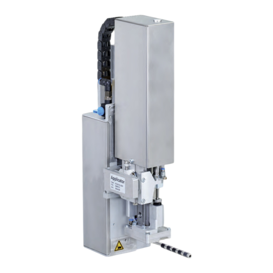
- Page 1 Assembly Instructions Stroke Applicator HQ 4014 / HQ 4016 MADE IN GERMANY...
- Page 2 9004002 Copyright This documentation as well as translation hereof are property of cab Produkttechnik GmbH & Co. KG. The replication, conversion, duplication or divulgement of the whole manual or parts of it for other intentions than its original intended purpose demand the previous written authorization by cab.
-
Page 3: Table Of Contents
Table of Contents Introduction ............................4 Instructions ............................... 4 Intended Use ............................4 Safety Instructions ............................ 4 Safety Markings ............................5 Environment ............................. 5 Product Description ..........................6 Important Features ........................... 6 Technical Data ............................6 Overview ..............................7 Contents of Delivery ..........................8 Pads ................................. -
Page 4: Introduction
• The device is designed to use on a cab printer of the HERMES Q series. Any other use or use going beyond this shall be regarded as improper use. The manufacturer/supplier shall not be liable for damage resulting from unauthorized use;... -
Page 5: Safety Markings
Introduction Before mounting the delivered components disconnect the printer from the power supply and close the shutoff valve of the • applicator. • Only connect the device to other devices which have a protective low voltage. Switch off all affected devices (computer, printer, accessories) before connecting or disconnecting. •... -
Page 6: Product Description
Product Description Important Features • The supporting air and the vacuum as well as the speed of the cylinder is adjustable. Thus the applicator can be adjusted to different label materials and sizes. • To avoid contamination within the vacuum channels they are cleaned by an air pressure pulse at the end of each application. -
Page 7: Overview
Product Description Overview Fig. 2 Device overview - front view 1 Cover 5 Blow tube for supporting air 2 Compressed air connector 6 Knurled screw for attaching the applicator to the printer 3 Shutoff valve 7 Hinges 4 Pad (customized) 8 SUB-D 15 interface to the printer... -
Page 8: Contents Of Delivery
Product Description Contents of Delivery 1. Applicator 2. Screws as part of the pad 3. Blow tube - as ordered 4. Pad - as ordered 5. Pen to make holes (only for universal pads) 6. Documentation Fig. 3 Contents of delivery Note! Please keep the original packaging in case the applicator must be returned. -
Page 9: Product Description
Product Description Pads 2.5.1 Universal Pads Universal pad 4014L/R-1100 Universal Pad 4014L/R-3100, spring-loaded Standard size : 70x60, 90x90 Standard size : 116x102, 116x152 Fig. 4 Universal pad 70x60 Fig. 5 Universal spring-loaded pad 116x152 Universal pads are available in different standard sizes. According to the size of the label the holes may be pierced by the customer. -
Page 10: Mounting
Mounting Fig. 9 Mounting applicator on printer Attention! Initiation, adjustments and changing of parts is only for qualified service personal only. Service Manual Mount the applicator 1. Hang the applicator with the female part of hinges (1) at the printer mounted hinges parts (2). 2. Connect SUB-D 15 male connector (6) to the female connector (7) of the printer. 3. -
Page 11: Mounting The Blow Tube
Mounting Mounting the Blow Tube Fig. 10 Mounting the blow tube It is possible to rotate the blow tube (4) to optimize the direction of the supporting air for the take over procedure of the label from printer to applicator. 1. -
Page 12: Preparing The Applicator For The Spring Mounted Pad 401X-4X00
Mounting Preparing the Applicator for the Spring Mounted Pad 401x-4x00 Attention! Ensure the cylinder assembly does not get damaged or cause injury when loosening screws to perform adjustments. Depending on the type of pad being used the cylinder assembly can be mounted at different heights. When delivered, the pad assembly is mounted in the lowest position as this is suited for most pads. -
Page 13: Adjusting The Pad
Mounting Adjusting the Pad For the perfect application of labels it is necessary that the pad is placed precisely above the dispensed label. Aligning the pad parallel to the dispensing plate The edge of the pad should be positioned parallel to the dispensing plate of the printer in order to position the label exactly on the pad. -
Page 14: Moving The Pad In Y-Direction
Mounting 3.5.1 Moving the Pad in Y-Direction 1 mm Fig. 15 Displacement in the Y direction Displacement in the Y direction (printing direction) 1. Loosen screws (1) on the cross beam (2). 2. Move cylinder assembly (4) with the pad (5) and crossbeam (2) along the guiding rail (3) that the distance from the edge of the pad (7) to the edge of the dispensing plate (8) of the printer is approximately 1 mm. -
Page 15: Moving The Pad In Z-Direction
Mounting 3.5.2 Moving the Pad in Z-Direction 1 mm Fig. 16 Displacement in the Z direction 1. Loosen screw (3) on the binder (2). 2. Turn the setting screw (1) so that the bottom side of the pad (4) is 1 mm over the top of the dispensing plate (6) of the printer. -
Page 16: Moving The Pad In X-Direction
Mounting 3.5.3 Moving the Pad in X-Direction Fig. 17 Displacement in the Y direction Displacement in the X direction (Side) 1. Loosen screw (3) on the binder (5). 2. Move cylinder assembly with the pad along the crossbeam (4) so that the dispensed label is aligned centrally to the pad. -
Page 17: Operation
Operation Standard Operation Check all external connections. Load the material. Ensure that the locking system is locked "Operator's Manual" of the printer. Open the shutoff valve. Attention! Ensure that the pad is not covered by a label when switching on the printer-applicator system. Otherwise the vacuum sensor may be calibrated faultily. -
Page 18: Configuration
Configuration Note! The settings in the printer configuration are basic settings for the specific printer-applicator combination. If the applicator or printer is changed, a new setting is required. Adaptation to the respective print job must be carried out primarily via the software. Additional offset values are available here. The offset values f rom the device settings and the software add up during operation. For detailed information about printer configuration Printer configuration manual Setting in the printer menu Note! This guide only describes the specific contents of the Labeling menu. More information about configuration Printer configuration manual. Start menu. Setup > Labeling. Select Parameter Meaning Default Cycle sequence... -
Page 19: Special Jscript Commands
Configuration Parameter Meaning Default Vacuum control Setting the label transfer check from printer to pad and from pad to product by the vacuum sensor Cleaning blow Activation of a short blow impulse after the application of the label to clean the suction channels. On - The vacuum will be switched on after the label feed is completed. -
Page 20: Error Messages
Error Messages Error Messages of the Printer For detailed information about printer errors (e.g. 'Paper out', 'Ribbon out', etc.) Check the operator's manual of the printer. Error treatment: Clearing the error results. Press the to synchronize the label feed, remove the left over labels manually. To quit the error state press Repeat . - Page 21 Error Messages Error treatment: Clear the error state. In order to clear the error state press continue, repeat or cancel. Continue with the next label in the printing queue. Repeat repeat the print of the label causing the error. Only applicable with error Vac.
-
Page 22: Licences
In the event of any alteration which has not been approved by us being made to any device as designated below, this statement shall thereby be made invalid. Applicator Device HQ 4014 / HQ 4016 Type Applied EU Regulations Applied Standards... -
Page 23: Eu Declaration Of Conformity
Annex II to Directive 2011/65/EU of the European Parliament and of the Council as regards the list of restricted substances Signed for, and on behalf of the Manufacturer Karlsruhe, 12.09.2024 cab Produkttechnik GmbH & Co KG Wilhelm-Schickard-Str. 14 Klaus Bardutzky D-76131 Karlsruhe Managing Director...
Need help?
Do you have a question about the HQ 4014 and is the answer not in the manual?
Questions and answers