Table of Contents
Advertisement
Quick Links
Advertisement
Table of Contents

Related Manuals for Chore-Time Chore-Tronics Model 8


Summary of Contents for Chore-Time Chore-Tronics Model 8
- Page 1 MT1554A August 1998...
-
Page 2: General
If such a defect is found by Chore-Time to exist within the one year period, Chore-Time will, at its option, (a) repair or replace such product free of charge, F.O.B. the factory of manufacture, or (b) refund to the original purchaser the original purchase price, in lieu of such repair or replacement. -
Page 3: Table Of Contents
Contents Topic Page General ............. 2 Chore - Time Warranty . - Page 4 Contents - continued Topic Page Set Temperature Curve........... . 26 Variable Speed .
-
Page 5: Support Information
Chore-Tronics Model 16 & 8 Control General Support Information Using this equipment for any other purpose or in a way not within the operating recommendations specified in this manual will void the warranty and may cause personal injury. As with all electronic controls, we recommend the use of a {Note} backup system. -
Page 6: Introduction
General Chore-Tronics Model 16 & 8 Control Introduction This manual is designed to provide comprehensive planning, installation, operation, and parts listing information. The Table of Contents provides a convenient overview of the information in this manual. Read this manual before operating your Control. If you have any questions regarding your Control, please contact your local Chore–Time dealer. -
Page 7: Safety Instructions And Warnings
Back-Up will be viewed as the user’s willingness to accept the risk of that loss. • Chore-Time takes no responsibility for any possible damage as a result of improper settings and non or partially functioning installation. • Chore-Time takes no responsibility for any possible damage due to failure,... -
Page 8: Notice To Electrician
Notice to Electrician Chore-Tronics Model 16 & 8 Control Notice to Electrician Each relay output in this Chore-Tronics control is designed to control 1 H.P. for many years of service. The relays are single pole, normally open contacts and break only one line of the power to the various loads. -
Page 9: Initial Setup
Chore-Tronics Model 16 & 8 Control Initial Setup Initial Setup 1. Referring to the drawing on page 32 (as was mentioned in the previous section), attach the small decals that are included with the control to the numbered toggle switches on the face of the control. The names of the devices (TUN FAN, EXH FAN, HT ZONE, COOL, etc.) have to be associated with the switch numbers which in turn correspond to the relay numbers. -
Page 10: Types Of Outputs
Initial Setup Chore-Tronics Model 16 & 8 Control Types of Outputs EXH FAN, TUN FAN, COOL AND STIR FAN (Relay contacts close, supplying power to the equipment on temperature rise). MT1553-01 4/98 Description Output Off Fan Off (temp falling) Fan On (temp rising) Output On Temperature Increasing HEAT ZONE... -
Page 11: Var Fan 1 & 2
Chore-Tronics Model 16 & 8 Control Initial Setup VAR FAN 1 & 2 MT1554-04 8/98 Description Minimum Speed 1 Minimum Speed 2 *Variable Fan 1 – on *Variable Fan 2 – on 2.5° Fahrenheit – minimum allowed .5° Fahrenheit – fixed Variable Fan #1 –... -
Page 12: Modes Of Operation
Initial Setup Chore-Tronics Model 16 & 8 Control Modes of Operation Power Mode POWER 5/98 Natural Mode NATURAL 5/98 Tunnel Mode TUNNEL 5/98 MT1554A 9/9/98 1/6/99... -
Page 13: Introduction To Control
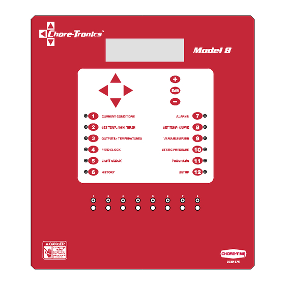
Chore-Tronics Model 16 & 8 Control Introduction to Control Introduction to Control Description of Control Front Panel MT1554-02 5/98 Item Description Model 16 Control Shown Viewing Screen Navigation Buttons Edit Buttons Relay Switches Subject Buttons * Model 8 has only 8 Relay Switches MT1554A 9/9/98... -
Page 14: Viewing Screen
Introduction to Control Chore-Tronics Model 16 & 8 Control Viewing Screen The viewing screen has a display which can show 8 lines, each containing 40 characters. This is the area that will display the requested information when a subject button is pressed. The viewing screen will always remain lit. When other subjects are not shown, the Current Conditions screen will be displayed Navigation Buttons These buttons allow you to scroll up and down in those few screens that have more... -
Page 15: Security
Chore-Tronics Model 16 & 8 Control Introduction to Control Security To provide for security in setting your controls, there is an optional security feature that will appear only when you initiate the Edit process. When you press the EDIT button, the control will automatically ask for an access code. This is a four digit number that you have selected while setting up the control and is explained under the “Set-Up and Calibration”... -
Page 16: How To Maneuver In The Viewing Screen
Introduction to Control Chore-Tronics Model 16 & 8 Control How to Maneuver in the Viewing Screen • The procedures below give a brief overview on the use of the Navigation Buttons and the Edit Buttons. • For this example we will be looking at the Setup and Calibration Screen. (Button 12 on the Control front panel). -
Page 17: Using The Edit Buttons
Chore-Tronics Model 16 & 8 Control Introduction to Control Using the Edit Buttons • This example gives you a brief summary on how to use the Edit Buttons in conjunction with the Navigation Buttons to edit values. • For this example we will be looking at the Setup and Calibration Screen. (BUTTON 12 on the Control front panel). - Page 18 Introduction to Control Chore-Tronics Model 16 & 8 Control 4. Press the DOWN ARROW (Figure 5). Figure 5. Setup and Calibration edit Screen. 5. Press the (+) or (–) buttons to change from Fahrenheit to Celsius. In this case the (+) and (–) buttons select different text choices. 6.
-
Page 19: Operation And Description Of Function Settings
Chore-Tronics Model 16 & 8 Control Operation and Description of Function Settings Operation and Description of Function Settings Current Conditions Screen • This screen shows a brief summary of the current conditions of the house. There are no editable values in this screen—it is for viewing only. Figure 6. -
Page 20: Set Temperature And Minimum Timer
Operation and Description of Function Settings Chore-Tronics Model 16 & 8 Control Set Temperature and Minimum Timer Figure 7. Model 16 Set Temp./Min. Timer Screen 1. Set Temperature - this is the temperature that you chose to operate your house at and the control will do its best to maintain. -
Page 21: Outputs-Temperatures
Chore-Tronics Model 16 & 8 Control Operation and Description of Function Settings Outputs–Temperatures • This Output Temperature screen describes how your control is set to operate. Figure 8. Model 16 Output Temperature Screen Output - This gives a complete list of each piece of equipment that is hard wired into the control through the relay panel and indicated in the Setup and Calibration —... -
Page 22: Feed Clock
Operation and Description of Function Settings Chore-Tronics Model 16 & 8 Control Feed Clock Figure 9. Feed Clock Screen 1. Number of Events - here you determine the number of feeding events you want by placing a number (up to 24) in this position. Whatever you choose will then show on the screen so you can put in the start and run times. -
Page 23: History
4. This is the water usage for each of the past six days. This input can be received from any water meter that has electrical {Note} output. Check with your Chore-Time distributor for compatible meters. This communication is established in the Setup and Calibration — BUTTON 12... -
Page 24: Alarms
Operation and Description of Function Settings Chore-Tronics Model 16 & 8 Control Alarms Figure 13. Alarms Screen The alarm output can be connected to external devices such as {Note} sirens or dialers. The control itself will present a visual display in screen “1”... - Page 25 Chore-Tronics Model 16 & 8 Control Operation and Description of Function Settings Alarms - continued 5. The maximum temperature limit is a backup to the limit established above, and not relative to set point. If the first limit due to the fact it is a relative limit is beyond an acceptable range, then the maximum temperature limit will activate the alarm.
-
Page 26: Set Temperature Curve
Operation and Description of Function Settings Chore-Tronics Model 16 & 8 Control Set Temperature Curve Figure 12. Set Temperature Curve Screen 1. Today’s Day - usually this would be the age of the birds or livestock at this moment. This also determines the position on the curve. 2. -
Page 27: Variable Speed
Chore-Tronics Model 16 & 8 Control Operation and Description of Function Settings Variable Speed Figure 13. Variable Speed Screen 1. Current Speed - this tells you the current speed of each variable speed output. 2. Minimum Speed - this allows you to set the minimum speed allowed for each variable speed output. -
Page 28: Static Pressure - Optional
Operation and Description of Function Settings Chore-Tronics Model 16 & 8 Control Static Pressure - optional Figure 14. Static Pressure Screen If you have elected not to use the optional static pressure control {Note} device, when you press this button it will advise you that static pressure is not in use. -
Page 29: Programs
Chore-Tronics Model 16 & 8 Control Operation and Description of Function Settings Programs This subject area provides you with two backup programs. A program is defined as all the settings of all 12 screens. Figure 15. Program Screen Important! {Note} Once step 3 below is done, you will not be able to retrieve the original installation setup. -
Page 30: Setup And Calibration
Operation and Description of Function Settings Chore-Tronics Model 16 & 8 Control Setup and Calibration • This is probably the most important screen in your control. This is the area that configures your control to meet the needs of your specific house management style. This setup should be done by a certified installer or distributor technician. - Page 31 Chore-Tronics Model 16 & 8 Control Operation and Description of Function Settings Setup and Calibration - continued All setups are performed in the Edit Mode with the use of the {Note} Navigation Buttons to move you around to editable positions and the (+) and (–) buttons to make changes and to answer questions.
-
Page 32: Actual House Layout
Operation and Description of Function Settings Chore-Tronics Model 16 & 8 Control Setup and Calibration - continued Actual House Layout 1. Indicate position of Main 1 and Main 2 curtains if used. 2. Indicate position of Sensors. 3. Fill in the list of relay numbers with device(s) each is controlling. Relay Device Controlled Suggested abbreviations for House Layout... - Page 33 Chore-Tronics Model 16 & 8 Control Operation and Description of Function Settings Setup and Calibration - continued Figure 16. System Setup and Calibration Screen. MT1554A 9/9/98...
- Page 34 Operation and Description of Function Settings Chore-Tronics Model 16 & 8 Control Setup and Calibration - continued Figure 16. System Setup and Calibration Screen. MT1554A 9/9/98 1/6/99...
- Page 35 Chore-Tronics Model 16 & 8 Control Operation and Description of Function Settings Setup and Calibration - continued 10. Mode Sensors - assign those sensors you wish to be each mode’s control sensor. These sensors determine when the control changes to a different mode. 11.
-
Page 36: Ms Board Dip Switch Positions
If you later decide you don’t want to use an access code, you simply change the access code back to “1111”. If you forget your access code, call Chore-Time. It is certainly recommended that you write down your access code in a safe place. -
Page 37: Variable Speed Dip Switch Positions
Chore-Tronics Model 16 & 8 Control Operation and Description of Function Settings Variable Speed Dip Switch Positions Switch position for first variable speed module. 1 2 3 2. Switch position for second variable speed module. 1 2 3 Since variable speed modules are added in the field, they will NOT {Note} come preset from the factory. -
Page 38: Technical Specifications
Technical Specifications Chore-Tronics Model 16 & 8 Control Technical Specifications This Information is to follow. MT1554A 9/9/98 1/6/99... -
Page 39: Pc Connection Overview
Chore-Tronics Model 16 & 8 Control PC Connection Overview PC Connection Overview Off-Site PC Connecting to On-Site PC with Controls MT1554A 9/9/98... -
Page 40: On-Site Pc With Controls
PC Connection Overview Chore-Tronics Model 16 & 8 Control On-Site PC with Controls MT1554A 9/9/98 1/6/99... -
Page 41: Off-Site Pc With Controls
Chore-Tronics Model 16 & 8 Control PC Connection Overview Off-Site PC with Controls MT1554A 9/9/98... -
Page 42: Trouble Shooting
Trouble Shooting Chore-Tronics Model 16 & 8 Control Trouble Shooting Problem Possible Cause Solution The Screen is blank, but The screen is defective. Replace the display. outputs appear to be The flat cable between the KD board and Readjust connections or replace operating normally. -
Page 43: Wiring Diagram
Chore-Tronics Model 16 & 8 Control Wiring Diagram Wiring Diagram This information is to follow. MT1554A 9/9/98... -
Page 44: This Information Is To Follow
Wiring Diagram Chore-Tronics Model 16 & 8 Control Wiring Diagram - continued This information is to follow. MT1554A 9/9/98 1/6/99... -
Page 45: Parts Listing
Chore-Tronics Model 16 & 8 Control Parts Listing Parts Listing MT1554-03 5/98 Opened Control Box Lid Control Box Base Item Description Part No. 8x40 Display 41317 KDCM.1 Keyboard Display Module 41315 MSCM.16-1 Switch circuit Board (Model 16) 41309 MSCM.8-2 Switch Circuit Board (Model 8) 41308 IOCM.1-3 Control Module (Model 16) 41321... - Page 46 Contact your nearby Chore-Time distributor or representative for additional parts and information. CTB Inc. P.O. Box 2000 • Milford, Indiana 46542-2000 • U.S.A. Phone (219) 658-4101 • Fax (800) 333-4191 EMail: ctb@ctbinc.com • Internet: http//www.ctbinc.com Printed in the U.S.A. MT1554A...
Need help?
Do you have a question about the Chore-Tronics Model 8 and is the answer not in the manual?
Questions and answers