
Subscribe to Our Youtube Channel
Related Manuals for Durr Dental Tornado 4


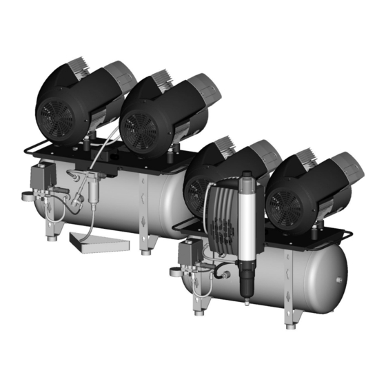
Summary of Contents for Durr Dental Tornado 4
- Page 1 Tornado 4 Installation and operating instructions 0297 9000-610-77/02 *9000-610-77/02*...
-
Page 3: Table Of Contents
Technical data ....13.2 Replacing the air intake filter ..Tornado 4 ....13.3 Replacing the filter in the con- Tornado 4 with membrane dry- densate separator . - Page 4 Contents Appendix 16 Handover record ....9000-610-77/02 1909V006...
-
Page 5: About This Document
These installation and operating instructions apply to: Observe the operating instructions. Tornado 4 Order number: 4280-01; 4280100022; 4282-01; Disconnect all power from the unit. 4282-03; 4282100006 Warnings and symbols Refer to the accompanying electronic documents. -
Page 6: Copyright Information
Important information Copyright information Safety All circuits, processes, names, software pro- Dürr Dental has designed and constructed this grams and units mentioned in this document are unit so that when used properly and for the protected by copyright. intended purpose it does not pose any danger to The Installation and Operating Instructions must people or property. -
Page 7: Safety
Important information Electrical safety WARNING Comply with all the relevant electrical safety ❯ Risk of explosion due to ignition of regulations when working on the unit. combustible materials Never touch the patient and unshielded plug ❯ Do not operate the unit in any rooms in ❯... -
Page 8: Disposal
Important information The original packaging provides optimum protec- tion for the unit during transport. Dürr Dental will not accept any responsi- bility or liability for damage occurring dur- ing transport due to the use of incorrect packaging, even where the unit is still under guarantee. -
Page 9: Overview
(possible variations due to country-spe- cific requirements and/or import regulations): Tornado 4 compressor ... . . 4280-01 Tornado 4 compressor ..4280100022 Tornado 4 compressor with mem- brane drying unit . -
Page 10: Technical Data
Product description Technical data Tornado 4 Electrical data 4280-01 4280100022 Rated voltage Mains frequency Nominal current at 8 bar (0.8 Mpa) 14.9 13.5 Motor protection Motor winding overheating protector and thermal protection switch Speed 1390 1650 Type of protection IP 24 Mains fuses * Max. -
Page 11: Operation
Product description Ambient conditions during storage and transport Temperature °C -10 to +55 Relative humidity max. 95 Ambient conditions during operation Temperature °C +10 to +40 Ideal temperature °C +10 to +25 Relative humidity max. 95 Classification Medical devices class 9000-610-77/02 1909V006... - Page 12 Product description Tornado 4 with membrane drying unit Electrical data 4282-01 4282-03 4282100006 Nominal voltage Electrical frequency Nominal current at 8 bar (0.8 Mpa) 15.0 13.6 Motor protection Motor winding overheating protector and thermal protection switch Speed 1390 1650 Type of protection...
- Page 13 Product description Ambient conditions during storage and transport Temperature °C -10 to +55 Relative humidity max. 95 Ambient conditions during operation Temperature °C +10 to +40 Ideal temperature °C +10 to +25 Relative humidity max. 95 Classification Medical devices class 9000-610-77/02 1909V006...
-
Page 14: Requirements
Product description Distance between rubber feet Compressor unit type plate Membrane drying unit The type plate of the membrane drying unit is located on the side of the membrane drying unit. a (cm) b (cm) 50 l 32.5 Type plate Complete system The type plate for the complete system is located on the motor support plate between the units. - Page 15 Product description Operation Tornado 4 type 4280-.. Compressor unit Air intake filter On/off switch Pressure switch Pressure gauge/display Pressure tank Mains connection for CEE connector 230 V / 16 A Safety valve Collector tray 10 Condensate separator 11 Fleece filter in condensate separator...
- Page 16 When removing air, the condensate is collected from the pressure tank into the condensate separator. As soon as a specific fill level is reached in the condensate separator, the condensate is dis- charged automatically. Tornado 4 type 4282-.. Compressor unit Air intake filter...
-
Page 17: Installation/Setup Room
Assembly Assembly ≥ 40 °C Requirements The unit must not be set up or operated within the vicinity of the patients (within a radius of 1.5 m). The unit can be installed either at the same level as the surgery room or on a floor below (e.g. cel- lar). -
Page 18: Transport
Assembly Transport Installation Remove the transport locks WARNING For safe transport, the unit is secured with foam Risk of explosion of the pressure tank padding blocks and a transport strap. and pressure hoses Cut and remove the transport strap. ❯ The pressure tank and the pressure ❯... - Page 19 Place a collector tray under the condensate ❯ separator or the membrane drying unit (depending on type). Fig. 1: Tornado 4 type 4280-.. Fig. 3: Tornado 4 type 4280-.. Fig. 2: Tornado 4 type 4282-.. Place a collector tray under-...
-
Page 20: Installation
Assembly Electrical connections Commissioning Before taking the unit into operation, check for ❯ Safety when making electrical connections any damage. Damaged units must not be The unit has no main power switch. For used. this reason it is important that the unit is In many countries technical medical prod- be set up in such a way that the plug can ucts and electrical devices are subject to... -
Page 21: Checking The Safety Valve
Assembly Read off the pressure when the unit switches ❯ WARNING If the readings deviate from the values preset at Risk of damage to the safety valve the factory, adjust the pressure switch to the Risk of explosion of the pressure tank factory settings. -
Page 22: Adjustment Options
Assembly 10 Adjustment options 10.1 Adjusting the pressure switch WARNING Risk of explosion of the pressure ves- The pressure vessels used in the com- pressors are designed to withstand continuous pressure changes of 2 bar and can be used continuously under these pressure changes. - Page 23 Assembly Adjust the start-up pressure via the pressure ❯ difference ∆p at the adjustment screw. The pressure difference increases in the "+" arrow direction and decreases in the "-" arrow direction. The maximum permissible pressure difference must not be set to more than 3 bar. 9000-610-77/02 1909V006...
-
Page 24: Circuit Diagram
Assembly 11 Circuit diagram P> X1 Mains connection for CEE connector 230 V / 16 A X2 Distributor for compressor units X3 Distributor for membrane drying unit (type 4282-... only) Q1 Pressure switch F1 Thermal protection switch, nominal current 12 A for M1 F2 Thermal protection switch, nominal current 12 A for M2 C1 Motor capacitor C2 Motor capacitor... -
Page 25: Usage
Usage Usage 12 Operation Prior to working on the unit or in case of danger, disconnect it from the mains. 12.1 Switching the unit on/off Switch on the unit at the pressure switch by ❯ rotating it to the position "I AUTO". The compressor unit will start up automatically and fill the pressure tank. -
Page 26: Maintenance
Usage 13 Maintenance Prior to working on the unit or in case of danger, disconnect it from the mains. CAUTION Risk of infection due to burst filters Particles enter the compressed air network and can therefore enter the mouth of the patient. Replace filters in accordance with the maintenance schedule. - Page 27 Usage Maintenance Maintenance work interval Every 5 years Replace the vibration reducers. ❯ Change the cup seal. ❯ In accordance with Check the safety valve. ❯ national law Carry out recurring safety inspections (e.g. pressure tank inspections, electrical ❯ safety inspections) in accordance with applicable national laws. 9000-610-77/02 1909V006...
-
Page 28: Replacing The Air Intake Filter
Usage Open the housing by rotating and pulling ❯ 13.2 Replacing the air intake filter downwards. Switch off the compressor at the pressure ❯ switch. Disconnect all power from the device. ❯ Release the filter cover by rotating it anti- ❯... - Page 29 Usage Re-assemble the condensate separator. ❯ During assembly pay attention to detents and markings. 13.4 Replacing the filter of the membrane drying unit Fine/sterile filter Switch off the unit. ❯ Disconnect all power from the device. ❯ Unscrew and remove the filter cover. ❯...
-
Page 30: Taking Out Of Use
Usage 14 Taking out of use 14.1 Taking the unit out of use If the unit is not to be used for a prolonged period of time, we recommend that it is properly shut down and taken out of use. To do this, the accumulated condensation water from the unit must be drained. -
Page 31: Storage Of The Unit
Usage 14.2 Storage of the unit WARNING Risk of explosion of the pressure tank and pressure hoses The pressure tank and the pressure ❯ hoses must be vented before they are stored or transported. Protect the unit against moisture, dirt and ❯... - Page 32 Troubleshooting Troubleshooting 15 Tips for operators and service technicians Any repairs exceeding routine maintenance may only be carried out by qualified personnel or our service. Prior to working on the unit or in case of danger, disconnect it from the mains. Error Possible cause Remedy...
- Page 33 Troubleshooting Error Possible cause Remedy Reduced delivery. Compres- Air intake filter dirty Replace the air intake filter at ❯ least 1x per year. The air sor needs longer to charge the pressure tank, see charg- intake filter must never be ing times in "4 Technical data"...
-
Page 34: Handover Record
Appendix Appendix 16 Handover record This document confirms that a qualified handover of the medical device has taken place and that appropriate instructions have been provided for it. This must be carried out by a qualified adviser for the medical device, who will instruct you in the proper handling and operation of the medical device. Product name Order number (REF) Serial number (SN) - Page 36 Hersteller/Manufacturer: DÜRR DENTAL SE Höpfigheimer Str. 17 74321 Bietigheim-Bissingen Germany Fon: +49 7142 705-0 www.duerrdental.com info@duerrdental.com...
Need help?
Do you have a question about the Tornado 4 and is the answer not in the manual?
Questions and answers