
Related Manuals for Advantech AIMB-228


Summary of Contents for Advantech AIMB-228
- Page 1 User Manual AIMB-228 AMD V-Series/R-Series Quad-Core Mini-ITX with 4 x DP, 6 x USB, 6 x COM, and 12 ~ 24V DC-In...
- Page 2 No part of this manual may be reproduced, copied, translated, or transmitted in any form or by any means without the prior written permission of Advantech Co., Ltd. The information provided in this manual is intended to be accurate and reliable.
- Page 3 Advantech has come to be known. Your satisfaction is our primary concern. Here is a guide to Advantech’s customer services. To ensure you get the full benefit of our services, please follow the instructions carefully.
-
Page 4: Declaration Of Conformity
Caution! New batteries are at risk of exploding if incorrectly installed. Do not attempt to recharge, force open, or heat the battery. Replace the battery only with the same or equivalent type as recommended by the manufac- turer. Discard used batteries according to the manufacturer's instruc- tions. AIMB-228 User Manual... - Page 5 SQR- K4A4G08 DDR4 2666 Advantech SD4N4G2K SD4N4G2K6SNE PASS 6SNEEB BCTD SEC 749 SQR- SQR- K4A8G08 DDR4 2400 16GB Advantech SD4M16G2 SD4M16G2K4SN PASS K4SNBB BCRC SEC 749 SQR- SQR- K4A4G08 DDR4 2400 Advantech SD4M4G2K SD4M4G2K4SNE PASS 4SNEEB BCRC AIMB-228 User Manual...
- Page 6 2400 Advantech SD4U8GE2 ECC PASS NAFR SD4U8GE24-HE 4-HE SEC 807 SQR- SQR- K4A4G08 DDR4 2666 Advantech SD4N4G2K SD4N4G2K6SEE ECC PASS 6SEEEB BCTD SEC 801 SQR- SQR- K4A8G08 DDR4 2666 16GB Advantech SD4N16G2 SD4N16G2K6SE ECC PASS K6SECB BCTD AIMB-228 User Manual...
-
Page 7: Ordering Information
*() BOM options available on MP version. Product Warranty (2 years) Advantech warrants the original purchaser that each of its products will be free from defects in materials and workmanship for two years from the date of purchase. This warranty does not apply to any products that have been repaired or altered by persons other than repair personnel authorized by Advantech, or products that have been subject to misuse, abuse, accident, or improper installation. -
Page 8: Initial Inspection
We have carefully inspected the AIMB-228 mechanically and electrically before shipment. The product should be free of marks and scratches and in perfect working order upon receipt. While unpacking AIMB-228, check the product for signs of shipping damage (for example, damaged box, scratches, or dents). -
Page 9: Table Of Contents
Jumper and Connector Locations ............. 9 Figure 1.1 Jumper and Connector Locations (Top Side)..... 9 Figure 1.2 Jumper and Connector Locations (Bottom Side)..10 Board Diagram ..................12 Figure 1.3 AIMB-228 Board Diagram ........12 Safety Precautions .................. 13 Jumper Settings ..................13 1.8.1 How to Set Jumpers.............. - Page 10 DisplayPort #3 (Up) + DisplayPort #4 (Down) Stack Connector (DP3+DP4) .........................65 USB 3.1 Gen 2 Stack Connector (USB23) ..........66 Serial ATA Interface Connector #1 (SATA1) .......... 66 USB 2.0 Stack Connector (USB14) ............66 5VSB Input Connector (ATX_5VSB1)............. 67 AT/ATX Mode Selection (PSON1) ............67 AIMB-228 User Manual...
- Page 11 COM4_RI# Pin Selection (JSETCOM4_V1) ........... 87 A.56 CCTALK Selection Pin Header (JCCT_VCON1) ........88 A.57 AT/ATX Mode Selection (PSON1) ............88 A.58 PWRBTN#/RESET#/HDD LED/Serial Bus/Internal Buzzer/External Speaker Header (JFP1) ................89 A.59 Watchdog Timer Output and OBS Beep (JWDT1+JOBS1) ....89 AIMB-228 User Manual...
- Page 12 AIMB-228 User Manual...
-
Page 13: Chapter 1 General Information
Chapter General Information... -
Page 14: Introduction
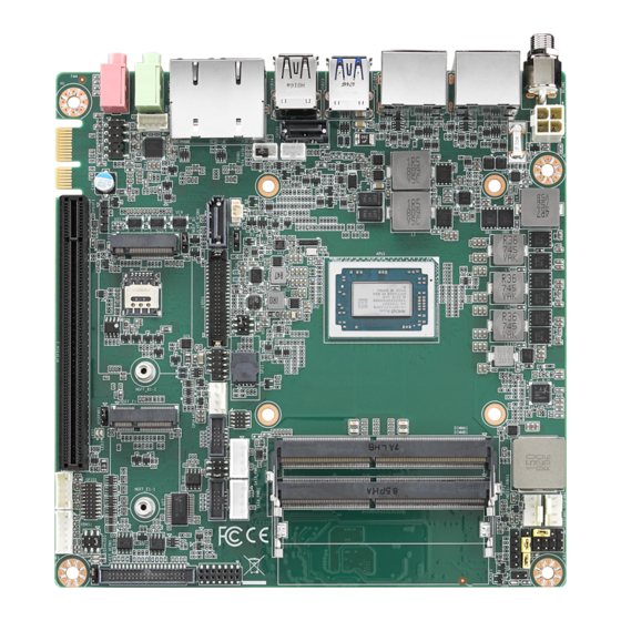
Introduction AIMB-228 is a mini-ITX motherboard based on the AMD Ryzen™ embedded V1000/ R1000 series processor that delivers superior graphics and computing performance. Designed with comprehensive I/O and four display outputs, AIMB-228 is ideal for multi-display applications such as digital surveillance, digital signage, electronic gam- ing machines, and thin client operations. -
Page 15: Sata Interface
Environment Temperature: – 0 ~ 60 °C (32 ~ 140 °F), operating – -40 ~ 85 °C (-40 ~ 185 °F), non-operating 1.3.12 Physical Characteristics Dimensions: 170 x 170 mm (6.69 x 6.69 in) AIMB-228 User Manual... -
Page 16: Jumpers And Connectors
Jumpers and Connectors The AIMB-228 motherboard features a number of jumpers and connectors that enable the integration of external devices, such as hard disk drives and a keyboard, and configuration according to specific applications. The function of each board jumper and connector is listed in the tables below. Later sections in this chapter provide instructions for setting jumpers. -
Page 17: Table 1.2: Jumper Setting List
JCASEOP_SW1 COM1_RI# pin selection pin header JSETCOM1_V1 LVDS VESA, JEIDA format selection pin header JLVDS_VCON1 Voltage selection for LVDS1/EDP1 connector (JLVDS1) Function Jumper Setting Jumper position for +3.3V (default) Jumper position for +5V Jumper position for +12V AIMB-228 User Manual... - Page 18 PWRBTN#/ RESET#/HDD LED/serial bus from HW monitor IC/internal buzzer/external speaker header (JFP1) Function Jumper Setting Internal buzzer (default) Watchdog timer output and OBS beep (JWDT1+ JOBS1) Function Jumper Setting Watchdog timer output (2-3) (default) OBS BEEP(4-5) (default) AIMB-228 User Manual...
- Page 19 AT mode Case open selection pin header (JCASEOP_SW1) Function Jumper Setting Normal close Normal open (default) COM1_RI# Pin RI#/5V/12V selection (JSETCOM1_V1) Function Jumper Setting Jumper position for RI# (default) Jumper position for +5V Jumper position for +12V AIMB-228 User Manual...
- Page 20 LVDS VESA, JEIDA format selection pin header (JLVDS_VCON1) Function Jumper Setting JEIDA mode (HI = +3.3V) VESA mode (Low = 0V) (default) AIMB-228 User Manual...
-
Page 21: Jumper And Connector Locations
Jumper and Connector Locations Top Layer Overview Figure 1.1 Jumper and Connector Locations (Top Side) AIMB-228 User Manual... -
Page 22: Figure 1.2 Jumper And Connector Locations (Bottom Side)
Bottom Layer Overview Figure 1.2 Jumper and Connector Locations (Bottom Side) AIMB-228 User Manual... - Page 23 COM1 RI# selection pin header JSETCOM1_V1 Inverter power connector INV1 16-bit general purpose I/O pin header GPIO1 PS2 keyboard/mouse connector KBMS1 COM4 RI# selection pin header JSETCOM4_V1 CCTALK voltage selection pin header JCCT_VCON1 COM3 ~ COM6 box header COM3456 AIMB-228 User Manual...
-
Page 24: Board Diagram
10 WA MP IC (Optional) 2 x USB 2.0 PCIex16 Slot 2 xUSB 2.0 USB Hub USB2.0 PCIex8 Support x8 signal PCIex1 2 x SATAIII PCIex1 SATA Golden Finger SATA 2 colay M.2 B-Key Figure 1.3 AIMB-228 Board Diagram AIMB-228 User Manual... -
Page 25: Safety Precautions
1, 2, and 3. In this case, connect either pins 1 and 2, or 2 and 3. A pair of needle-nose pliers may be useful when setting jumpers. AIMB-228 User Manual... -
Page 26: Cmos Clear (Jcoms1)
AT mode System Memory AIMB-228 is equipped with two sockets for 260-pin SODIMM. These sockets are compatible with 1.2V unbuffered double-data-rate synchronous, low-voltage DRAM (DDR4 SDRAM). DRAM is available in capacities of 1, 2, 4, 8, and 16 GB. The socket supports any combination of DIMMs of any size, for a total memory size of 2 to 32 GB. -
Page 27: Chapter 2 Connecting Peripherals
Chapter Connecting Peripherals... -
Page 28: Introduction
USB Ports (USB 23/14/56) AIMB-228 provides up to six USB ports (2 x USB 3.1 and 2 x USB 2.0 on the rear side and 2 x USB 2.0 via the board pin header). The USB interface complies with USB Rev. -
Page 29: Displayport1/2/3/4 (Dp12/Dp34)
DisplayPort1/2/3/4 (DP12/DP34) AIMB-228 features 4 x DP connectors. Serial Ports (COM1~COM6) AIMB-228 supports six serial ports (COM1 and COM6 support RS-232 function, COM2 and COM5 support RS-232/422/485 function via jumper setting, COM3 colay CCTalk, and COM4 colay TTL). These ports can be connected to serial devices, such as a mouse or printer, or a communications network. -
Page 30: Cpu Fan Connector (Cpu_Fan1)
CPU Fan Connector (CPU_FAN1) This connector supports cooling fans of 500 mA (6 W) or less. System Fan Connector (SYSFAN1/2) This connector supports cooling fans of 500 mA (6 W) or less. AIMB-228 User Manual... -
Page 31: Power Switch/Hdd Led/Smbus/Speaker Pin Header (Jfp1), Power Led, And Keyboard Lock Pin Header (Jfp2)
Power Switch/HDD LED/SMBUS/Speaker Pin Header (JFP1), Power LED, and Keyboard Lock Pin Header (JFP2) There are several headers for monitoring and controlling the AIMB-228. 2.7.1 ATX Soft Power Switch (JFP1/PWR_SW) If your computer case is equipped with an ATX power supply, connect the power on/ off button on the computer case to JFP1/ PWR_SW for convenient operation. -
Page 32: Dc Input Jack And 4-Pin Atx Connector (Dcin1)
DC Input Jack and 4-Pin ATX Connector (DCIN1) SATA Signal and Power Connector (SATA1~SATA2/SATA_PWR1~2) AIMB-228 features a high-performance serial ATA III interface (up to 600 MB/s) that supports thin space-saving cables to streamline hard drive cabling. AIMB-228 User Manual... -
Page 33: Hd Analog Audio Interface (Audio1, Audio2, Fpaud1)
Connect this connector with the front-panel audio I/O module cable. Note! For motherboards with the optional HD Audio feature, we recommend connecting a high-definition front-panel audio module to this connector to take advantage of the motherboard's high-definition audio capability. AIMB-228 User Manual... -
Page 34: Pci-E X16 Slot (Pciex16_1)
2.11 PCI-E x16 Slot (PCIEX16_1) AIMB-228 provides 1 x PCI express x16 slot. 2.12 Low-Voltage Differential Signaling Interface (LVDS1) AIMB-228 User Manual... -
Page 35: Lvds Backlight Inverter Power Connector (Inv1)
2.13 LVDS Backlight Inverter Power Connector (INV1) 2.14 NGFF M.2 B-Key and E-Key Connector (M2B1 & M2E1) AIMB-228 User Manual... -
Page 36: Audio Amplifier Output Connector (Amp1), Bom Optional
2.15 Audio Amplifier Output Connector (AMP1), BOM Optional 2.16 General Purpose I/O Pin Header (GPIO1) AIMB-228 User Manual... -
Page 37: Spi Bios Flash Socket (Spi1)
2.17 SPI BIOS Flash Socket (SPI1) 2.18 SPI Programming Pin Header (SPI_CN1) AIMB-228 User Manual... -
Page 38: Low-Pin-Count Header (Lpc1)
2.19 Low-Pin-Count Header (LPC1) 2.20 Case-Open Detect Connector (JCASE1) AIMB-228 User Manual... -
Page 39: Cmos Battery Connector (Bat1)
2.21 CMOS Battery Connector (BAT1) 2.22 DDR4 SODIMM Socket (DIMMA1, DIMMB1) AIMB-228 User Manual... - Page 40 AIMB-228 User Manual...
-
Page 41: Bios Operation
Chapter BIOS Operation... -
Page 42: Introduction
AIMB-228 BIOS menus. BIOS Setup The AIMB-228 system has AMI BIOS built in and features a CMOS SETUP utility that allows users to configure required settings or activate certain features. The CMOS SETUP saves the configuration in the CMOS RAM of the motherboard. When the power is turned off, the battery on the board supplies the necessary power to pre- serve the CMOS RAM. -
Page 43: Main Menu
System Date using the <Arrow> keys. Enter new values via the keyboard. Press the <Tab> or <Arrow> keys to move between fields. The date must be entered in MM/DD/YY format. The time must be entered in HH:MM:SS format. AIMB-228 User Manual... -
Page 44: Advanced Bios Features
BIOS setup option by highlighting it using the <Arrow> keys. All Advanced BIOS setup options are described in this section. The Advanced BIOS setup screen is shown below. The sub menus are described in the following sections. AIMB-228 User Manual... - Page 45 ACPI Sleep State [Auto] This item allows users to select the ACPI sleep state the system will enter when the SUSPEND button is pressed. Lock Legacy Resources [Disabled] This item allows users to enable/disable locking of legacy resources. AIMB-228 User Manual...
- Page 46 3.2.2.3 NCT6776 Super IO Configuration Super IO Chip [NCT6776] Serial Port 1 Configuration AIMB-228 User Manual...
- Page 47 Serial Port 2 Configuration Serial Port [Enabled] – Device Settings: IO = 2F8h; IRQ = 3 – Change Setting [Auto] This item allows users to select the optimal settings for serial port 2. Digital I/O Configuration AIMB-228 User Manual...
- Page 48 Digital I/O Pin 1 - 16 [Input] AIMB-228 User Manual...
- Page 49 ACPI Shutdown Temperature [Disabled] This item allows users to enable/disable the ACPI shutdown temperature function and set the threshold value. When the system reaches the shutdown temperature, it will automatically shut down to protect the system from over- heating damage. AIMB-228 User Manual...
- Page 50 This item allows users to view the CPU temperature and fan speed (PWM) infor- mation. SYS Fan Mode [SMART FAN IV Mode] This item allows users to view the system temperature and fan speed (PWM) information. AIMB-228 User Manual...
- Page 51 3.2.2.5 NCT5114D Super IO Configuration Serial Port 3 Configuration AIMB-228 User Manual...
- Page 52 Serial Port 4 Configuration Serial Port 5 Configuration AIMB-228 User Manual...
- Page 53 Serial Port 6 Configuration 3.2.2.6 S5 RTC Wake Settings This item allows users to enable/disable the system-wake-on-alarm function. AIMB-228 User Manual...
- Page 54 Wake System with Fixed Time [Disabled] Note! When enabled, the system will wake at the specified time. 3.2.2.7 Serial Port Console Redirection Console Redirection [Enabled] This item allows users to enable/disable the console redirect function. AIMB-228 User Manual...
- Page 55 3.2.2.8 Network Stack Configuration [Disabled] Network Stack [Disabled] Note! When the network stack function is enabled, the LANx PXE OpROM must be enabled. AIMB-228 User Manual...
- Page 56 1. Re-install the OS in UEFI mode. 2. Change all of the above settings to Legacy mode. * Boot option filter -> Legacy only * Network -> Legacy * Storage -> Legacy * Video -> Legacy * Other PCI devices -> Legacy AIMB-228 User Manual...
- Page 57 USB Hardware Delays and Timeouts This item allows users to configure the USB device transfer and reset timeout and delay settings. Mass Storage Devices [Auto] This item allows users to view USB mass storage device information. AIMB-228 User Manual...
-
Page 58: Chipset Configuration Setting
This item allows users to view details of the display items. North Bridge Configuration This item allows users to configure the north bridge settings. Platform Misc Configuration This item allows users to view the platform configuration information. AIMB-228 User Manual... -
Page 59: South Bridge Configuration
SB USB Configuration This item allows users to configure the USB settings. SB SATA Configuration This item allows users to configure the SATA settings. SB MSIC Configuration This item allows users to configure miscellaneous settings. AIMB-228 User Manual... -
Page 60: Gfx Configuration
3.3.2 GFX Configuration LVDS Panel Type [Disabled] AIMB-228 User Manual... -
Page 61: North Bridge Configuration
3.3.3 North Bridge Configuration 3.3.4 Platform Misc Configuration System Configuration [Auto] PCIE x16 Slot [Enabled] LAN1 Controller [Enabled] AIMB-228 User Manual... -
Page 62: Security Settings
<ENTER> to access the sub-menu. Then input the desired password. User Password This item allows users to set the user password. Select this option and press <ENTER> to access the sub-menu. Then input the desired password. AIMB-228 User Manual... -
Page 63: Boot Setting
This item allows users to enable/disable quiet bootup. If this option is disabled, the BIOS will display normal POST messages. If enabled, an OEM logo is dis- played instead of POST messages. Boot Option #1/#2 This item allows users to set the device bootup priority. AIMB-228 User Manual... -
Page 64: Save & Exit Configuration
BIOS without making changes to the system configuration. 1. Select Reset Discard Changes from the Exit menu and press <Enter>. The following message appears: Discard changes and exit setup now? [Ok] [Cancel] 2. Select ok or cancel. AIMB-228 User Manual... - Page 65 Save as User Default This item allows users to save all current settings as the user default. Restore User Default This item allows users to restore all settings to the user default values. AIMB-228 User Manual...
- Page 66 AIMB-228 User Manual...
-
Page 67: Software And Services
Chapter Software and Services... -
Page 68: Introduction
OS distributors). Value-Added Software Services AIMB-228 is equipped with software APIs that define the ways by which application programs may request services from libraries and/or operating systems. Advantech provides the required drivers as well as a comprehensive set of user-friendly, intelli- gent, and integrated interfaces, which speed development, enhance security, and offer add-on value for Advantech platforms. -
Page 69: Software Utility
ROM BIOS version, or back up the current BIOS set- tings by copying the data from the flash chip to a file. The BIOS flash utility also provides a command line and API for rapid implementation in customized applications. AIMB-228 User Manual... - Page 70 OS crash, the eSOS will boot up. It will diag- nose the hardware and send an e-mail to the designated administrator. The eSOS also supports remote connectivity via a Telnet or FTP server. However, this function must be configured in the BIOS. AIMB-228 User Manual...
-
Page 71: Chipset Software Installation Utility
Chapter Chipset Software Installation Utility... -
Page 72: Before Beginning
Before Beginning To ensure problem-free installation of the enhanced display drivers and utility soft- ware, read the instructions in this chapter carefully. The drivers for AIMB-228 can be downloaded from the Advantech website. Updates are provided via Microsoft service packs. -
Page 73: Lan Configuration
Chapter LAN Configuration... -
Page 74: Introduction
Please follow the instructions for the appropriate oper- ating system. Windows 10 Driver Setup Visit the Advantech website to obtain the required drivers. Select the LAN folder then navigate to the directory for your OS. AIMB-228 User Manual... -
Page 75: Appendix A I/O Pin Assignments
Appendix I/O Pin Assignments... -
Page 76: Atx 12V Power Supply Connector (Atx12V1)
ATX 12V Power Supply Connector (ATX12V1) Signal 12V ~ 24V 12V ~ 24V DC Input Jack (DCIN1) Signal VCC (Center) DisplayPort #1 (Up) + DisplayPort #2 (Down) Stack Connector (DP1+DP2) Signal Signal ML_0+ ML_0- ML_1+ ML_1- ML_2+ ML_2- ML_3+ ML_3- AIMB-228 User Manual... -
Page 77: Displayport #3 (Up) + Displayport #4 (Down) Stack Connector (Dp3+Dp4)
Stack Connector (DP3+DP4) Signal Signal ML_0+ ML_0- ML_1+ ML_1- ML_2+ ML_2- ML_3+ ML_3- Config1 AUX+ AUX- Hot plug detect VCC (+3.3V) ML_0+ ML_0- ML_1+ ML_1- ML_2+ ML_2- ML_3+ ML_3- Config1 AUX+ AUX- Hot plug detect VCC (+3.3V) AIMB-228 User Manual... -
Page 78: Usb 3.1 Gen 2 Stack Connector (Usb23)
USB 3.1 Gen 2 Stack Connector (USB23) Signal Signal VBUS VBUS Serial ATA Interface Connector #1 (SATA1) Signal Advantech defined USB 2.0 Stack Connector (USB14) AIMB-228 User Manual... -
Page 79: 5Vsb Input Connector (Atx_5Vsb1)
Signal Signal VBUS VBUS 5VSB Input Connector (ATX_5VSB1) Signal +5V AUX PS_ON# AT/ATX Mode Selection (PSON1) Signal +3.3V AIMB-228 User Manual... -
Page 80: Dual-Port Rj45 Connector (Lan12)
Audio Amplifier Output Pin Header (AMP1) Signal AMP OUT - R+ AMP OUT - R- AMP OUT - L- AMP OUT - L+ A.12 HD Audio Interface (Line-Out) (AUDIO1) Signal LINE OUT - L LINE OUT - R AIMB-228 User Manual... -
Page 81: Hd Audio Interface (Mic-In) (Audio2)
A.14 Front Panel Audio Header (FPAUD1) Signal Signal MIC IN - L MIC IN - R FPAUD_DETECT# LINE OUT - R SENSE R1 SENSE LINE OUT - L SENSE R2 A.15 CMOS Battery Wafer Box (BAT1) Signal AIMB-228 User Manual... -
Page 82: Serial Ata Interface Connector #2 (Sata2)
A.16 Serial ATA Interface Connector #2 (SATA2) Signal A.17 HD Audio Interface (SPDIF1) Signal SPDIF OUT A.18 LVDS VESA, JEIDA Format Selection Pin Header (JLVDS_VCON1) Signal +3.3V Advantech defined AIMB-228 User Manual... -
Page 83: M.2 B-Key (Ngff_B1)
UIM - DATA PETn1 / USB3.1-Tx- UIM - PWR PETp1 / USB3.1-Tx+ PERn0 / SATA-RX+ PERp0 / SATA-RX- PETn0 / SATA-TX- PETp0 / SATA-TX+ PERST# CLKREQ# REFCLKn PEWAKE# REFCLKp RESET# SUSCLK(32kHz) CONFIG_1 +3.3V AUX +3.3V AUX +3.3V AUX CONFIG_2 AIMB-228 User Manual... -
Page 84: Low-Voltage Differential Signaling (Lvds1)
ED1+ OD2- ED2- OD2+ ED2+ OCK- ECK- OCK+ ECK+ DDC CLK DDC DAT OD3- ED3- OD3+ ED3+ LVDS ENBKL LVDS VCON A.21 SIM Card Holder (SIM1) Signal SIM PWR SIM RESET SIM CLK SIM VPP SIM DATA AIMB-228 User Manual... -
Page 85: Pci Express X16 Slot (Pciex16_1)
PWRGD Reserved REFCLK+ TX0+ REFCLK- TX0- RX0+ Advantech defined RX0- Advantech defined TX1+ Reserved TX1- RX1+ RX1- TX2+ TX2- RX2+ RX2- TX3+ TX3- RX3+ Reserved RX3- Reserved Reserved TX4+ Reserved TX4- RX4+ RX4- TX5+ TX5- RX5+ RX5- AIMB-228 User Manual... - Page 86 TX6+ TX6- RX6+ RX6- TX7+ TX7- RX7+ Reserved RX7- Reserved AIMB-228 User Manual...
-
Page 87: Usb 2.0 Front-Panel Header (Usb56)
USB 2.0 Front-Panel Header (USB56) Signal Signal VBUS VBUS A.24 CPU Fan #1 Connector (CPUFAN1) Signal CPU fan VCC CPU fan speed CPU fan PWM A.25 USB Power Selection for USB12/34/56 (JUSBPWR1) Signal +5V AUX Advantech defined AIMB-228 User Manual... -
Page 88: M.2 E-Key Connector (Ngff_E1)
USB_D- Wi-Fi_LED# I2S SCK I2S WS I2S SD_IN I2S SD_OUT BT_LED# UART WAKE# UART RXD UART TXD UART CTS PETp0 UART RTS PETn0 PERp0 PERn0 REFCLKp0 REFCLKn0 SUSCLK PERST0# CLKREQ0# W_DISABLE2# PEWAKE0# W_DISABLE1# +3.3V AUX +3.3V AUX AIMB-228 User Manual... -
Page 89: Com2 Box Header (Com2)
TXD [2] CTS# [2] DTR# [2] RI# [2] A.28 COM1 RI# Selection Pin Header (JSETCOM1_V1) Signal Signal RI# [6] Advantech defined Advantech defined +12V Advantech defined A.29 Inverter Power Connector (INV1) Signal +12V BKL EN BKL CTRL AIMB-228 User Manual... -
Page 90: 16-Bit General Purpose I/O Pin Header (Gpio1)
GPIO6 GPIO14 GPIO7 GPIO15 +5V AUX A.31 Keyboard and Mouse Connector (KBMS1) Signal KB_CLK# KB_DAT# MS_CLK# +5V AUX MS_DAT# A.32 COM4 RI Selection Pin Header (JSETCOM4_V1) Signal Signal RI# [6] Advantech defined Advantech defined +12V Advantech defined AIMB-228 User Manual... -
Page 91: Cctalk Voltage Selection Pin Header (Jcct_Vcon1)
CTS# [4] DTR# [4] RI# [4] DCD# [5] DSR# [5] RXD [5] RST# [5] TXD [5] CTS# [5] DTR# [5] RI# [5] DCD# [6] DSR# [6] RXD [6] RST# [6] TXD [6] CTS# [6] DTR# [6] RI# [6] AIMB-228 User Manual... -
Page 92: Com1 Box Header (Com1)
A.36 Low-Pin-Count Interface Connector (LPC1) Signal Signal LPC CLK LPC AD1 LPC RESET# LPC AD0 LPC FRAME# +3.3V LPC AD3 LPC AD2 SMB_CLK LPC SERIRQ SMB_DATA +5V AUX A.37 Serial ATA Power Connector #1 (SATA_PWR1) Signal +12V AIMB-228 User Manual... -
Page 93: Serial Ata Power Connector #2 (Sata_Pwr2)
DDR4 SODIMM Socket CH-B (DIMMB1) Please see JEDEC STANDARD. A.41 Power LED & Keyboard Lock Pin Header (JFP2) Signal Power LED Keyboard Lock A.42 Watchdog Timer Output and OBS Beep (JWDT1+JOBS1) Signal RESET# SIO BEEP FRP BEEP AIMB-228 User Manual... -
Page 94: Case Open Connector (Jcase1)
A.43 Case Open Connector (JCASE1) Signal Case Open A.44 PWRBTN#/RESET#/HDD LED/Serial Bus From HW Monitor IC/Internal Buzzer/External Speaker Header (JFP1) Signal Signal HDD LED+ PWRBTN+ SPK_P2 HDD LED- PWRBTN- SPK_P3 SMB_DATA RESET+ SPK_P4 SMB_CLK RESET- AIMB-228 User Manual... -
Page 95: System Fan #2 Connector (Sysfan2)
Signal SYSTEM FAN VCC SYSTEM FAN SPEED SYSTEM FAN PWM A.46 System Fan #1 Connector (SYSFAN1) Signal SYSTEM FAN VCC SYSTEM FAN SPEED SYSTEM FAN PWM A.47 SPI Pin Header (SPI_CN1) Signal Signal +1.8V MISO SCLK MOSI AIMB-228 User Manual... -
Page 96: Spi Bios Flash Socket (Spi1)
A.48 SPI BIOS Flash Socket (SPI1) Signal Signal MOSI MISO SCLK HOLD# +3.3V A.49 VDD Select for LVDS1 Panel (JLVDS1) Signal Signal +12V +3.3V A.50 COMS Mode Selection (JCMOS1) Signal VBAT AIMB-228 User Manual... -
Page 97: Usb Power Selection For Usb12/34/56 (Jusbpwr1)
PSON1 PWRBTN#/RESET#/HDD LED/serial bus/internal buzzer/ JFP1 external speaker header Watchdog timer output and OBS beep JWDT1+JOBS1 A.51 USB Power Selection for USB12/34/56 (JUSBPWR1) Function Jumper Setting Set USB VBUS as +5VSB (default) Set USB VBUS as +5V AIMB-228 User Manual... -
Page 98: Vdd Select For Lvds1 Panel (Jlvds1)
A.52 VDD Select for LVDS1 Panel (JLVDS1) Function Jumper Setting Jumper position for +3.3V (default) Jumper position for +5V Jumper position for +12V A.53 CMOS Clear (JCOMS1) Function Jumper Setting Normal (default) Clear CMOS data AIMB-228 User Manual... -
Page 99: Com1_Ri# Pin Selection (Jsetcom1_V1)
COM1_RI# Pin Selection (JSETCOM1_V1) Function Jumper Setting Jumper position for RI# (default) Jumper position for +5V Jumper position for +12V A.55 COM4_RI# Pin Selection (JSETCOM4_V1) Function Jumper Setting Jumper position for RI# (default) Jumper position for +5V AIMB-228 User Manual... -
Page 100: Cctalk Selection Pin Header (Jcct_Vcon1)
Jumper position for +12V A.56 CCTALK Selection Pin Header (JCCT_VCON1) Function Jumper Setting CCTALK 12V (default) CCTALK 5V A.57 AT/ATX Mode Selection (PSON1) Function Jumper Setting ATX mode (default) ATX mode AIMB-228 User Manual... -
Page 101: Pwrbtn#/Reset#/Hdd Led/Serial Bus/Internal Buzzer/External Speaker Header (Jfp1)
Buzzer/External Speaker Header (JFP1) Function Jumper Setting Internal buzzer (default) A.59 Watchdog Timer Output and OBS Beep (JWDT1+JOBS1) Function Jumper Setting Watchdog timer enable (2-3) (default) OBS beep (4-5) (default) Watchdog timer disable (1-2) OBS beep (4-5) (default) AIMB-228 User Manual... - Page 102 No part of this publication may be reproduced in any form or by any means, such as electronically, by photocopying, recording, or otherwise, without prior written permission from the publisher. All brand and product names are trademarks or registered trademarks of their respective companies. © Advantech Co., Ltd. 2019...
Need help?
Do you have a question about the AIMB-228 and is the answer not in the manual?
Questions and answers