Table of Contents
Advertisement
Quick Links
Advertisement
Table of Contents

Related Manuals for ATEQ AX6000


Summary of Contents for ATEQ AX6000
- Page 1 USER MANUAL ATEQ AX6000 Version 03.03 Reference: UM-30300D-U...
- Page 3 REVISIONS OF THE ATEQ AX6000 USER MANUAL Due to continuing improvements, the information contained in this user manual, the features and design of this device are subject to be changed without prior notice. Date Edition/Revision Reference Chapters up dating Week/Year...
-
Page 5: Declaration Of Conformity
0940/CE-30300A-U DECLARATION OF CONFORMITY 00 We the undersigned, ATEQ, manufacturers of the ATEQ AX6000 REF : 303.00 declare that it complies with the requirements of : - LOW VOLTAGE Directive 73/23/CEE partially modified by Directive 93/68/CEE. • standard EN 61 010-1 « Safety requirements for electrical equipment for measurement, control and laboratory use »,... - Page 7 ATEQ is at your disposal for any further information concerning the use of the instrument under maximum safety conditions. We would like to bring to your attention that ATEQ will not be held...
- Page 9 ATEQ is attached to the COFRAC and delivers a certificate following a calibration. TRAINING COURSES In the framework of partnership with our customers, ATEQ offers two types of training in order to optimise the usage and knowledge of our instruments. They are aimed at different levels of technician: •...
- Page 11 PREFACE Dear Customer, You have just purchased an ATEQ instrument, we thank you for the trust you have placed on our brand. This instrument has been designed to ensure a long and unparalleled life expectancy, and we are convinced that it will give you complete satisfaction during many long years of operation.
-
Page 13: Table Of Contents
Table of contents TABLE OF CONTENTS Preamble MEASUREMENT PRINCIPLE 1. DEFINITION ............................3 2. PRINCIPE.............................3 3. GENERAL DIAGRAM..........................4 4. AUTOMATIC ZERO..........................5 5. BATTERY / INSTRUMENT AUTONOMY....................5 6. MEASUREMENT CHARACTERISTIC ....................6 6.1. Measurement ranges selection ....................6 Chapter 1 INSTRUMENT INSTALLATION 1. APPEARANCE ............................7 2. - Page 14 Chapter 6 ERROR MESSAGES ERROR MESSAGES ....................45 Chapter 7 OPERATIONAL PROBLEMS 1. PROBABLES FAILURES........................47 Appendices ATEQ AX6000 1. TECHNICALS CHARACTERISTICS....................49 2. DIMENSION DRAWING ........................49 3. SAFETY INFORMATION........................50 4. RECYCLING ............................52 Index UM-30300D-U User manual AX 6000 Page 2 / 54...
-
Page 15: Definition
Preamble Preamble MEASUREMENT PRINCIPLE 1. DEFINITION The AX 6000 instrument is a milliohmmeter designed to test metallization encountered in aviation. This quality test controls the mechanical assembly of each part who constituting a plane. For this, he characterized the control of the junction between two or more parts using the principle of measuring electrical continuity. -
Page 16: General Diagram
Preamble 3. GENERAL DIAGRAM Current 10 A generator 0.1 A Shunt Voltmeter Automatic zero Instrumentation amplifier UM-30300D-U User manual AX 6000 Page 4 / 54... -
Page 17: Automatic Zero
Preamble 4. AUTOMATIC ZERO During its measurement cycle, the instrument carried out automatically an auto-zero measurement to eliminate undesirables' thermo-electrics effects in the measurement circuit and carried out the measurement zero of the instrument compensating the offset errors in the measurement amplifier. Then, at each measurement, the instrument memorizes the spurious external voltage of the thermocouple present in the R terminal before the passage of the current in... -
Page 18: Measurement Characteristic
Preamble 6. MEASUREMENT CHARACTERISTIC Measurement Range Accuracy Resolution Current 1 µΩ 6 mΩ +/- (0.1 % MV + 6 µΩ) 1 µΩ 0.1A 100 µΩ 60 mΩ +/- (0.1 % MV + 60 µΩ) 1A – 10A 10 µΩ 600 mΩ 0.1A –... -
Page 19: Chapter 1 Instrument Installation
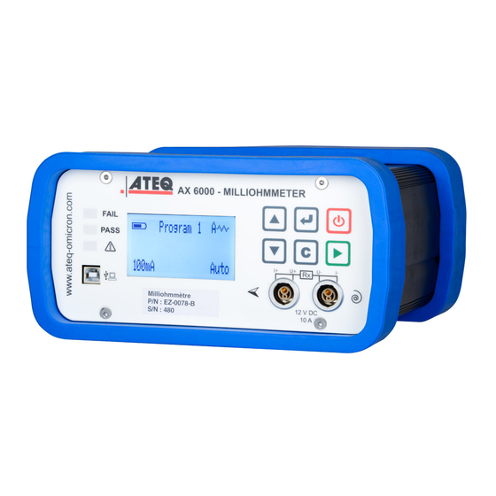
Chapter 1 INSTRUMENT INSTALLATION 1. APPEARANCE The ATEQ AX6000 case is made with two anodized aluminum parts assuring durability and lightness. The case is surrounded by two rubbers to protects the device from falls and avoid marking the shocked part. -
Page 20: Instrument Installation
Chapter 1 – Instrument installation 2. INSTRUMENT INSTALLATION 2.1. B ATTERY BLOCK UPPLY The ATEQ AX6000 is running with a 12 V DC battery. The battery has a LED light for charge state: Red: The battery is charging. Green: battery full. -
Page 21: Electrics Connectors
Chapter 1 – Instrument installation 2.2. E LECTRICS CONNECTORS 2.2.1. Test accessories connectors The test accessories, probes, Kelvin probes pliers, etc. are connected on these two plugs. There are two connectors on the front face and two on the rear face that the user will choose following the use. - Page 22 Chapter 1 – Instrument installation UM-30300D-U User manual AX 6000 Page 10 / 54...
-
Page 23: Chapter 2 User Interfaces
Chapter 2 – User interfaces Chapter 2 USER INTERFACES 1. PRESENTATION Results lights connector Navigation and Tests control keys connectors Display UM-30300D-U User manual AX 6000 Page 11 / 54... -
Page 24: Keyboard Presentation
Chapter 2 – User interfaces 2. KEYBOARD PRESENTATION 2.1. O FF KEY FUNCTION Instrument off: this key switch on the device. Instrument on: this key switch off the device by long pressing (more than 3 seconds). 2.2. N AVIGATION KEYS FUNCTION Move up or increase the numeric values. -
Page 25: Lcd Display
Chapter 2 – User interfaces 3. LCD DISPLAY To display the measurement results and the parameters to adjust. AX 6000 V1.11a Display detail: Battery level Test mode Program 1 Test result 1.000 mΩ Value Range PASS 6mΩ Test current Test result 4. -
Page 26: Carrying Case
Chapter 2 – User interfaces 6. CARRYING CASE Note: The color of the carrying case can change without notice. AX 6000 Accessories Batteries Important note: do not charge the battery when it installed into the carrying case, you must remove it to avoid overheating. See the instructions concerning the battery in the appendices. -
Page 27: Open The Carrying Case
Chapter 2 – User interfaces 6.1. O PEN THE CARRYING CASE Push the two buttons at the bottom of the locks. The locks will be released. Lift the two locks to release the cover. Then open the cover to access to the instrument. -
Page 28: Close The Carrying Case
Chapter 2 – User interfaces 6.2. C LOSE THE CARRYING CASE Before closing the housing box, open the purge button (left turn). Close the cover and lock the two locks. Then close the purge button (right turn) to complete the sealing. UM-30300D-U User manual AX 6000 Page 16 / 54... -
Page 29: Starting Up And Adjustments
Chapter 3 – Starting up and adjustments Chapter 3 STARTING UP AND ADJUSTMENTS 1. TURN ON THE DEVICE The AX6000 is running with its integrated battery. Switches on the instrument. AX 6000 V3.02 Check the battery level. Program 1 The instrument waits a start. -
Page 30: Lock / Unlock
Chapter 3 – Starting up and adjustments 2. LOCK / UNLOCK This function allows locking the test parameters access; this to avoid any hazardous parameters modification. The password by default is 0000. 2.1. L OCK OPERATION MAIN MENU >Parameters: Unlock Press and hold the key (three seconds) to enter into the Mode : Program... -
Page 31: Unlock Operation
Chapter 3 – Starting up and adjustments 2.2. U NLOCK OPERATION MAIN MENU >Parameters: Lock Press and hold the key (three seconds) to enter into the Mode : Program main menu, select the Parameters : Lock function. Program : Pr01 PASSWORD MODE >Unlock To unlock the parameters access, select the Unlock function. -
Page 32: Mode Function
Chapter 3 – Starting up and adjustments 3. MODE FUNCTION The instrument had two test modes, the Program mode and the Sequence mode. The Program mode allows running programs individually and unitary. The program to run choice is made by the user. The programs can be created from the front face of the device or from the Winateq300 software. -
Page 33: Test Program Creation
Chapter 3 – Starting up and adjustments 4. TEST PROGRAM CREATION MAIN MENU >Parameters : Unlock Press and hold the key (three seconds) to enter into the Mode : Program main menu. Program : Pr01 MAIN MENU In the main menu, put the cursor in front of Program to select Parameters : Unlock Mode : Program the program to edit and validate with the... -
Page 34: Parameters Adjust
Chapter 3 – Starting up and adjustments 5. PARAMETERS ADJUST Now adjust the test cycle parameters. The process to adjust the parameters is the same for all. MAIN MENU Parameters : Unlock Press and hold the key (three seconds) to enter into the Mode : Program main menu. - Page 35 Chapter 3 – Starting up and adjustments 5.1.4. Minimum reject (R Min) This parameter defines the threshold below which the test part is considered as fail. If the measured value does not exceed this value, the test is fail. Note: the measurement result must be between the minimum reject and the maximum reject to be declared pass, if not the test will be fail.
- Page 36 Chapter 3 – Starting up and adjustments Automatic mode: this mode allows detecting if the circuit is inductive or resistive. Following the characteristics of the measured circuit, the device will adapt its measurement. The icon displayed on the right top of the screen show the mode. If the circuit is resistive, the device displays the symbol: If the circuit is inductive, the device displays the symbol: Note: in the case of installation of a reel on the measurement circuit, it will be...
-
Page 37: Measurement Triggering
Chapter 3 – Starting up and adjustments 6. MEASUREMENT TRIGGERING The measurement is triggered by: Simple accessories contact on the part to test (current detection). If the Auto Start function is on. Press the key on the instrument front face. During measurement, hourglass... -
Page 38: Sequences Configuration (Winateq300/Ax)
Chapter 3 – Starting up and adjustments 8. SEQUENCES CONFIGURATION (WINATEQ300/AX) The sequences configuration can be done only with the Winateq300 6000 software. The sequence mode allows chaining several programs the ones after the others following a defined order that the operator may follow. Maximum characteristics: 128 programs;... -
Page 39: Available Commands Detail
Chapter 3 – Starting up and adjustments 8.2. A VAILABLE COMMANDS DETAIL Global Actions menu: Reset All: deletes all the sequences in the device. Download: to save on the PC hard drive all the sequences ("Sequences.seq" files). Upload: to restore from the PC hard drive the sequences ("Sequences.seq" files). - Page 40 Chapter 3 – Starting up and adjustments Insert Before: to insert the program above the selected step. Insert After: to insert the program below the selected step. 8.3.3. Sequence management The "Up", "Remove" and "Down" keys allows moving the programs in the sequence.
-
Page 41: Sequence Mode Running
Chapter 3 – Starting up and adjustments 9. SEQUENCE MODE RUNNING The sequence mode allows chaining several programs the ones after the others following a defined order. Each program is a step. The sequences can contain until 999 steps. A test program can be several times in the same sequence, or in several sequences. -
Page 42: Sequence Selection
Chapter 3 – Starting up and adjustments 9.2. S EQUENCE SELECTION "Wings" With the keys, select the sequence to carry out (here S01). We access the "Operator" menu (see below). Start Seq.+/- Empty sequence If the sequence doesn't exist, the message "Empty sequence"... -
Page 43: Change A Step Attribute
Chapter 3 – Starting up and adjustments Note: the user can at any time navigate through the sequence by pressing the keys. So, he can see the measurement values for each step and see the remains steps. 9.5. C HANGE A STEP ATTRIBUTE The user can "jump"... -
Page 44: Display Age The Sequences Filters
Chapter 3 – Starting up and adjustments 9.6.1. Sequence validation SPECIAL CYCLES Select the "Seq. validation" menu to record it and press the >Seq. validation Seq. cancellation key. Tests -TO DO- VALIDATION SEQUENCE The validation menu is displayed, press the key to Confirm confirm. -
Page 45: Menu Structure
Chapter 4 – Functions of the instrument Chapter 4 FUNCTIONS OF THE INSTRUMENT 1. MENU STRUCTURE 1.1. M AIN MENU To access to the main menu, press and hold the ENTER key until the main menu appears (about 3 seconds). MAIN MENU Under menu 1 Under menu 2... -
Page 46: Special Cycles Menu
Chapter 4 – Functions of the instrument MAIN MENU Under menu 1 Under menu 2 Under menu 3 > Month Year Hour Minutes Backlight > 0% to 100% (step 10%) Auto off > No to 30 min Buzzer > On / Off Automatic Start >... -
Page 47: System Settings
Chapter 4 – Functions of the instrument 2. SYSTEM SETTINGS The SYSTEM SETTINGS menu allows configuring the instrument following the user preferences. In all cases, to access to the SYSTEM SETTINGS menu, Press MAIN MENU and hold the key (three seconds) to enter to the Range : Auto Mode : Resistive... -
Page 48: Date And Hour
Chapter 4 – Functions of the instrument 2.2. D ATE AND HOUR The device gets a clock (hour, minutes) and an internal calendar (day, month, year) which allows dating the events and the archives. 2.2.1. Date SYSTEM SETTINGS MENU In the SYSTEM SETTINGS menu, select the Date function and Language : English >Date : 10/08/09 validate with the... -
Page 49: Lighting The Screen
Chapter 4 – Functions of the instrument 2.2.2. Hour Proceed in the same way as the date for setting the time. SYSTEM SETTINGS MENU In the SYSTEM SETTINGS menu, select the Hour function and Date : 10/08/09 >Hour : 10:25 validate with the key. -
Page 50: Auto Off
Chapter 4 – Functions of the instrument 2.4. A This feature conserve battery life by automatically turning the instrument off after a user- defined period of time within there has been no key activity. SYSTEM SETTINGS MENU In the SYSTEM SETTINGS menu, select the Auto Off function Hour : 10:25 Backlight : 60%... -
Page 51: Automatic Start
Chapter 4 – Functions of the instrument 2.6. A UTOMATIC START The Automatic start function allows validating the automatic trigger of the measurement when the accessories are making an electric contact with the part to control (current control). SYSTEM SETTINGS MENU In the SYSTEM SETTINGS menu, select the Auto Start >Auto Start : Off... -
Page 52: Data Management
Chapter 4 – Functions of the instrument 3. DATA MANAGEMENT 3.1. R ESULTS STORAGE The device is fitted with an internal memory greater than 1 Go only used for the results storage, that allows recording several thousands of measurements results. Each measurements carried out are automatically save at the end of the test. -
Page 53: Specials Cycles Menu
Chapter 4 – Functions of the instrument 3. SPECIALS CYCLES MENU 3.1. S PECIAL CYCLES AVAILABLE The following list shows all the special cycles which are available in the instrument: Special cycle Function Auto-test: Special cycle used to check the test current. To delete the current sequence, canceling all the tests Sequence delete*: carried out in the sequence and starts the sequence... - Page 54 Chapter 4 – Functions of the instrument AUTO TEST RANGE Select the range to check among 100 mA, 1 A and 10 A, by None 100mA using the keys, confirm with the key. >1A Program 1 The instrument confirms the special cycle and the selected current.
-
Page 55: Chapter 5 Accessories
Chapter 5 - Accessories Chapter 5 ACCESSORIES 1. ACCESSORIES 1.1. P OWER SUPPLY The power supply (fitted with the instrument) converts a network voltage (100 to 240 V AC) into a 24 V DC low voltage supply. It has no power switch and works as soon as it is plugged in. -
Page 56: Usb Cable
1.5. T RANSPORT CASE Strong case with the dimensions: Large 520, Depth 440 and high 230 for the storage of the following components: 1 measurement device AX6000, 1 second battery, 1 power supply for battery charging, 1 probe small size,... -
Page 57: Chapter 6 Error Messages
Chapter 6 –Error messages Chapter 6 ERROR MESSAGES The ATEQ AX6000 can display error messages if there are operational problems. PROBLEM LIGHTS DISPLAYED MESSAGES Program 1 The measure is out of the full scale. OVER Action: take another measurement RANGE range, or configure the instrument in 6mΩ... - Page 58 SD CARD the programs modifications are not FAULT saved. Auto Action: contact ATEQ after sales services. A fatal internal system error occurs. SYSTEM ERROR Action: try to switch of and restart the instrument, if the problem persists, contact ATEQ after sales services.
-
Page 59: Probables Failures
ATEQ after sales service. 7) Contact the ATEQ after sales service. The ATEQ Company disclaims any responsibility if the instruments calibration and adjustment would not be performed by its services. UM-30300D-U User manual AX 6000 Page 47 / 54... - Page 60 Chapter 7 - Operational problems UM-30300D-U User manual AX 6000 Page 48 / 54...
-
Page 61: Appendices Ateq Ax6000
Appendices Appendices ATEQ AX6000 1. TECHNICALS CHARACTERISTICS AX 6000 Power supply: 24 V DC concentric jack Battery: Lithium Polymer (see safety information below) Weight (kg): About 2,8 Display : LCD 4 lines 60 mm x 32 mm Temperatures: Use and battery charge: 0°... -
Page 62: Safety Information
Use a specified charger approved by the ATEQ manufacturer and supplied with the device. Safety for Lithium Polymer battery use NEVER leave the battery unattended during the charging process. - Page 63 The ATEQ Company couldn't control the proper use of the battery for each customer (charge, discharge, storage etc.), It can not be held responsible for damage to persons and property.
-
Page 64: Recycling
This applies to your tool but also to any enhancements marked with this symbol. Do not dispose of these products as unsorted municipal waste. For further information, please contact ATEQ. UM-30300D-U User manual AX 6000 Page 52 / 54... -
Page 65: Index
Index Index Lock / Unlock ........18 Alarm ..........13 Auto off ..........38 Main menu ..........33 Automatic mode........24 Maximum reject ........22 Automatic start........39 Measurement characteristics ....6 Automatic zero........5 Measurement modes ......23 Auto-test ........25, 41 Measurement principle ......3 Measurements fail ......25 Backlight ..........37 Minimum reject ........23 Battery ..........50 Battery charge indicator......8... - Page 66 Index Tests -N/A- .........32 Turn on ..........17 USB ............9 Turn on key.........12 What to do in case of failure? .....47 UM-30300D-U User manual AX 6000 Page 54 / 54...
- Page 68 This document is the exclusive property of ATEQ. It may not be communicated, reproduced or used without prior consent.
Need help?
Do you have a question about the AX6000 and is the answer not in the manual?
Questions and answers