
Subscribe to Our Youtube Channel
Related Manuals for Barco MDSC-8358 RL


Summary of Contents for Barco MDSC-8358 RL
- Page 1 MDSC-8358 User Guide MDSC-8358 RL - MDSC-8358 RLG MDSC-8358 RLF - MDSC-8358 RLH (451920612552) K5902150/01 28/11/2017...
- Page 2 Barco NV Beneluxpark 21, 8500 Kortrijk, Belgium Phone: +32 56.23.32.11 Fax: +32 56.26.22.62 Support: www.barco.com/en/support Visit us at the web: www.barco.com Registered address: Barco NV President Kennedypark 35, 8500 Kortrijk, Belgium Phone: +32 56.23.32.11 Fax: +32 56.26.22.62 Support: www.barco.com/en/support Visit us at the web: www.barco.com...
-
Page 3: Table Of Contents
Table of contents TABLE OF CONTENTS 1. Welcome! ..................3 About the product .................... . 3 What’s in the box. - Page 4 Table of contents (451920612552) K5902150 MDSC-8358 28/11/2017...
-
Page 5: Welcome
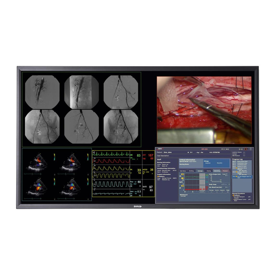
About the product Overview The Barco Medical Grade MDSC-8358 series are color high resolution liquid crystal displays especially designed for medical imaging applications. The MDSC-8358 is a 58” Color Flat Panel Display, intended to replace typical multi-monitor arrays in med- ical applications, whenever a large display is needed in addition to high resolution, while offering the same good rendering in greyscale medical imaging thanks to the DICOM conformance. -
Page 6: About This User Guide
1. Welcome! Keep your original packaging. It is designed for this display and is the ideal protection during transport. The user guide is available in other languages on www.barco.com. About this user guide Overview This manual provides support to the user during the installation, set up and utilization of the MDSC-8358 display. -
Page 7: Parts, Controls And Connectors
2. Parts, controls and connectors 2. PARTS, CONTROLS AND CONNECTORS Front view Overview Image 2-1 1. Power On/Off 2. Enter key 3. Down key 4. Up key 5. Esc key A 5-key keypad is located on the bottom of the display. (451920612552) K5902150 MDSC-8358 28/11/2017... -
Page 8: Rear View
2. Parts, controls and connectors Rear view Overview Image 2-2 1. VESA mount screw holes 2. Connector location Connector view Connectors 6 10 6 10 Image 2-3 (451920612552) K5902150 MDSC-8358 28/11/2017... -
Page 9: Connector Pin Assignments
2. Parts, controls and connectors 1. Additional protective earth pin 2. Input power connector 3. RS-232 connector 4. Switch (between RS-232 & Ethernet) 5. Ethernet connector for monitor remote control 6. DVI-D single link / dual link connector (*) 7. +5V out connector 8. -
Page 10: Rs232 Connector
2. Parts, controls and connectors D3_RX+ (T.M.D.S) +5V input (form the video source system) +5V Power for DVI extenders D0_Rx- (T.M.D.S.) D0_Rx+ (T.M.D.S.) GND (data 0 shield) D5_RX- (T.M.D.S.) D5_RX+ (T.M.D.S.) GND (clock shield) CK_Rx+ (T.M.D.S.) CK_Rx- (T.M.D.S.) 2.4.2 RS232 connector Overview Image 2-5 Function... -
Page 11: Display Installation
3. Display installation 3. DISPLAY INSTALLATION Hoist bracket installation Two brackets are provided in the accessory kit to be used for service per- ARNING sonal only. The hoist brackets are intended to be used during the monitor’s installation ARNING phase only. To mount and use the hoist bracket to the display 1. - Page 12 3. Display installation 3. After transportation, you can remove the brackets and the 8 mounting holes can be closed, either with 8 plastic caps (version without the protection glass) or using the same screws adding the respective o-ring (version with the protection glass). (451920612552) K5902150 MDSC-8358 28/11/2017...
-
Page 13: Vesa Mount Installation
3. Display installation VESA mount installation Overview The display supports mounting arm & stands according to the VESA 400 mm standard. Use an arm that is in compliance with VESA requirements. AUTION AUTION The monitor VESA interface has been designed for a safety factor 6 (to sup- port 6 times the monitor weight). -
Page 14: Video Input Connection
3. Display installation The arm or stand is not provided. The product stability must be verified in AUTION the specific usage (according to IEC 60601-1 Clause 9.4.2.2) To mount the display to an arm stand 1. Attach the mounting arm or the stand firmly to the display using minimum 6 screws (M6) pointed out by the red arrows in the image below. -
Page 15: Video Output Connection
3. Display installation Image 3-2 Overview possible inputs 1. DVI 2. DisplayPort 3. DVI splitter Video output connection ARNING When the display is assembled in the medical system, take care of the an- chorage of all cables, to avoid unwanted detachment. To connect the video outputs 1. - Page 16 3. Display installation 2. Plug the power connector of the adapter into the power port of the display. Image 3-4 3. For additional grounding, earth the display by connecting the protective earth pin to a grounded outlet by means of a wire with a minimum AWG18 size (according to national requirements regarding the maximum admitted cable length).
-
Page 17: Daily Operation
4. Daily operation 4. DAILY OPERATION On/Off switching About power management: The display has 2 keys: • Main power switch (to switch of all power to the display). • Push button to enter/exit the Power Down Mode. The display can go in three different statuses: •... -
Page 18: Brightness Adjustment
4. Daily operation Brightness adjustment To quickly adjust the brightness 1. While no OSD Menu is on the screen, press the Up/Down keys to adjust the brightness as desired. The brightness will be displayed in a window in the upper-left corner. by pressing the Up/Down keys simultaneously, the default brightness will be restored (400 cd/m²... -
Page 19: Osd Menu Unlocking
4. Daily operation • If the selected menu item is controlled by a slider use the up/down keys to adjust the item value, then press the enter key to confirm. • If the selected menu item is a multiple choices menu use the up/down keys to select the desired option then press the enter key to confirm. - Page 20 4. Daily operation (451920612552) K5902150 MDSC-8358 28/11/2017...
-
Page 21: Advanced Operation
5. Advanced operation 5. ADVANCED OPERATION Product info About product info The available information items for your display are: • HWREL: Hardware release • FWREL: Firmware release • S/N: Serial number To view the product info 1. Bring up the OSD main menu. 2. -
Page 22: Transfer Function
5. Advanced operation 3. Enter the Brightness info submenu. Transfer function About transfer function There are different transfer function possibilities: • Native: the transfer function is transparent (no correction is applied). • DICOM (Factory): The output curve follows the DICOM transfer function and is automatically adapted to the current brightness. -
Page 23: Input Channel Selection
5. Advanced operation Input channel selection Overview • Input channel menu • Failover input 5.7.1 Input channel menu About input channel menu Possibility to select the following inputs: • DISPLAYPORT • DISPLAYPORT FAILOVER • DVI 1 • DVI 2 • DVI 3 •... -
Page 24: Osd Setting Menu
5. Advanced operation To select the failover input 1. Bring up the OSD main menu. 2. Navigate to the Input menu. 3. Select one of the available failover inputs and confirm. OSD setting menu 5.8.1 Time-out OSD About time-out OSD When the OSD menu is displayed and no key is pressed, it will disappear after the time set in this menu. -
Page 25: Setup Menu
5. Advanced operation 6. Change the status of OSD menu lock as desired and confirm. Setup menu About setup menu The available information items for your display are: • FACTORY: Factory settings • USER: User settings To select the setup: 1. - Page 26 5. Advanced operation (451920612552) K5902150 MDSC-8358 28/11/2017...
-
Page 27: Important Information
6. Important information 6. IMPORTANT INFORMATION Safety information General recommendations Read the safety and operating instructions before operating the device. Retain safety and operating instructions for future reference. Adhere to all warnings on the device and in the operating instructions manual. Follow all instructions for operation and use. - Page 28 6. Important information Power connection – Equipment with internal power supply • This equipment must be earthed. • Power requirements: The equipment must be powered by the AC mains voltage. • The equipment should be installed near an easily accessible outlet. •...
-
Page 29: Technical Data
Sufficient expertise is required for installing this equipment, especially to determine the strength of the wall for withstanding the display’s weight. Be sure to entrust the attachment of this equipment to the wall to licensed contractors of Barco and pay adequate attention to safety during the installation and usage. -
Page 30: Environmental Information
For more information about recycling of this product, please contact your local city office or your municipal waste disposal service. For details, please visit the Barco website at: http://www.barco.com/en/AboutBarco/weee Turkey RoHS compliance Türkiye Cumhuriyeti: AEEE Yönetmeliğine Uygundur. - Page 31 Mainland, marked with the Environmental Friendly Use Period (EFUP) logo. The number inside the EFUP logo that Barco uses (please refer to the photo) is based on the “General guidelines of environ- ment-friendly use period of electronic information products” of Chinese Mainland.
-
Page 32: Biological Hazard And Returns
The manufacturing country of the product is indicated on the product label (“Made in …”). Importers contact information To find your local importer, contact one of Barco’s regional offices via the contact information provided on our website (www.barco.com). FCC Class A This equipment has been tested and found to comply with the limits of a class A digital device, pursuant to Part 15 of the FCC rules. -
Page 33: Cleaning And Disinfection
6. Important information tion manual, may cause harmful interference to radio communications. Operation of this equipment in a residential area is likely to cause harmful interference in which case the user will be required to correct the interference at his own expense. Canadian notice This ISM device complies with Canadian ICES-001. - Page 34 6. Important information Indicates the device is approved according to the CCC regulations Indicates the device is approved according to the VCCI regulations Indicates the device is approved according to the KC regulations Indicates the device is approved according to the BSMI regulations Indicates the device is approved according to the PSE regulations Indicates the device is approved according to the RCM regulations Indicates the device is approved according to the EAC regulations...
- Page 35 6. Important information Indicates the device part number or catalogue number Warning: dangerous voltage Caution Consult the operating instructions Indicates this device must not be thrown in the trash but must be recycled, according to the European WEEE (Waste Electrical and Electronic Equipment) directive Indicates Direct Current (DC) Indicates Alternating Current (AC)
-
Page 36: Legal Disclaimer
Barco software products are the property of Barco. They are distributed under copyright by Barco NV or Barco Inc., for use only under the specific terms of a software license agreement between Barco NV or Barco Inc. and the licensee. No other use, duplication, or disclosure of a Barco software product, in any form, is authorized. - Page 37 6. Important information Color imaging Color support 16 million Viewing angle (H, V) 88° Maximum luminance 700 cd/m² (typical) Contrast ratio typ. 4000:1 Response time 9.5ms (typical) Housing color Black Audio Headphones Microphone Audio line (in and out) PC connection Micro USB interface on the go Device mode: no max.
- Page 38 6. Important information EN 55011 / CISPR11 (Class A) FCC CFR 47 Part 15 Subpart B (Class A) Marks: CE; DEMKO; c-UR-us Supplied accessories User Guide Warranty 2 years Operating temperature 10–35°C for performance / 0–40°C for safety (temperature change <1°C/min.;...
- Page 39 6. Important information Dimensions 1318.5 459.25 459.25 Image 6-1 (451920612552) K5902150 MDSC-8358 28/11/2017...
-
Page 40: Open Source License Information
A list of the Open Source Software components used is available in the applicable EULA, through the “My Barco” section of the Barco website or through other (online) means. Copyright on each Open Source Software component belongs to the respective initial copyright holder, each additional contributor and/or their respective assignee(s), as may be identified in the respective Open... - Page 41 Barco whatsoever. You further acknowledge that any such additions, changes or modifications may impair the ability of Barco – at Barco’s sole discretion - to continue to provide ser- vice, warranties, software updates, fixes, maintenance, access or such similar abilities, without any recourse or claim towards Barco whatsoever.
- Page 42 6. Important information (451920612552) K5902150 MDSC-8358 28/11/2017...
-
Page 43: Rs-232 Protocol
7. Appendix A 7. APPENDIX A RS-232 protocol About RS-232 protocol The communication protocol of the monitor is based upon user oriented commands and factory oriented commands. The following description is related to the user oriented commands and is based on the MDSC-8358 monitors user commands. - Page 44 7. Appendix A 2a) Get Current Transfer Function: PC > monitor: <ESC> O <CR> monitor > PC: (character) <CR><LF> where (character) has the following meaning: (character) Current Transfer Function 0 (zero) NATIVE DICOM GAMMA 1 GAMMA 2 the character O in the command sequence is the letter “o” in uppercase. 2b) Set Transfer Function: PC >...
- Page 45 7. Appendix A 4b) Keylock status: PC > monitor: <ESC> k? monitor > PC: (character) where (character) has the following meaning: (character) Keylock 0 (zero) Disable Enable 4c) Keylock code: PC > monitor: <ESC> v???? monitor > PC: <ACK> where “?” is a number between 1 and 4 which codifies the key according to the following table: “?”...
Need help?
Do you have a question about the MDSC-8358 RL and is the answer not in the manual?
Questions and answers