Table of Contents
Advertisement
Quick Links
Advertisement
Table of Contents

Subscribe to Our Youtube Channel
Related Manuals for Omron AC1-152000


Summary of Contents for Omron AC1-152000
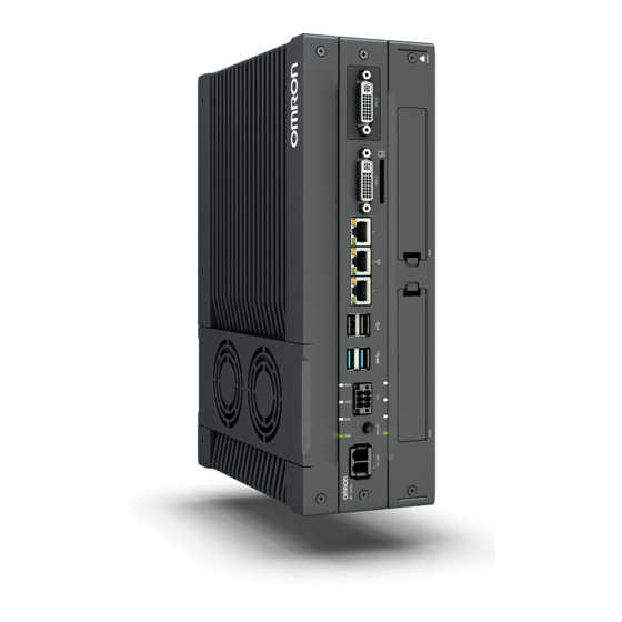
- Page 1 IPC Application Controller User's Manual I632-E-03...
- Page 2 Every precaution has been taken in the preparation of this manual. Nevertheless, OMRON assumes no responsibility for errors or omissions. Neither is any liability assumed for damages resulting from the use of the information contained in this publica- tion.
-
Page 3: Intended Audience
• Personnel in charge of managing Factory Automation systems and facilities. Applicable Products This manual covers following IPC Application Controller products: Product Model IPC Application Controller AC1-152000 Additional Information Refer to 1-4 Product Configuration on page 1-5 for configuration details. IPC Application Controller User's Manual (I632) - Page 4 Introduction IPC Application Controller User's Manual (I632)
-
Page 5: Sections In This Manual
Sections in this Manual Sections in this Manual Overview Hardware Software Specifications Installation Operating Procedures Maintenance Appendices IPC Application Controller User's Manual (I632) -
Page 6: Table Of Contents
CONTENTS CONTENTS Introduction ......................1 Intended Audience............................1 Applicable Products ............................1 Sections in this Manual ................... 3 Manual Information....................9 Page Structure..............................9 Special Information ............................10 Terms and Conditions Agreement................ 11 Warranty, Limitations of Liability ........................11 Application Considerations ..........................12 Disclaimers ..............................13 Safety Precautions.................... - Page 7 CONTENTS Section 1 Overview Intended Use .........................1-2 Hardware Features.........................1-3 ID Information Label Application Controller ...............1-4 Product Configuration......................1-5 Section 2 Hardware Layers and Components .......................2-2 2-1-1 Cooling Layer ..........................2-3 2-1-2 Base Layer ..........................2-4 2-1-3 Expansion Layer (Optional)......................2-5 LED Indicators........................2-6 2-2-1 PWR LED Indicator ........................2-6 2-2-2 ERR LED Indicator ........................2-7 2-2-3...
- Page 8 CONTENTS 3-3-2 Installed IPC Support Software ....................3-5 3-3-3 Industrial PC Support Utility .......................3-6 3-3-4 Rescue Disk Creator ......................... 3-11 3-3-5 Industrial PC Tray Utility ......................3-18 3-3-6 Power Attendant Lite Utility .......................3-21 Section 4 Specifications General Specifications ......................4-2 4-1-1 Dimensions and Weight ......................4-2 4-1-2 General Electrical Specifications....................4-3 4-1-3...
- Page 9 CONTENTS 5-5-2 Connection Procedure ......................5-35 Initial Power ON ........................5-37 5-6-1 Initial Power ON Procedure.......................5-37 5-6-2 Windows Startup First Time ......................5-39 Install Software ........................5-41 5-7-1 Firewall ............................5-41 5-7-2 Anti-virus Software ........................5-41 5-7-3 Drivers and Custom Software ....................5-42 5-7-4 Activate Windows ........................5-42 Connect UPS ........................5-43 5-8-1 Connect UPS Using the USB Connector ..................5-44...
- Page 10 CONTENTS Appendices BIOS ............................A-2 A-1-1 BIOS Overview........................... A-2 A-1-2 BIOS for 7 generation CPUs....................A-4 Customize Windows ......................A-7 A-2-1 Trusted Platform Module ......................A-7 RS-232C Connector Pin Details................... A-8 DVI Connector Pin Details....................A-9 A-4-1 DVI-I Connector Pin Details ....................... A-9 Index IPC Application Controller User's Manual (I632)
-
Page 11: Manual Information
Manual Information Manual Information This section provides information about this manual. Page Structure The following page structure is used in this manual. 5 Installation Unpack This section provides details on how to unpack the Industrial Panel PC. 5-1-1 Unpack Procedure Check the package for damage. -
Page 12: Special Information
Manual Information Special Information Special information in this manual is classified as follows: Precautions for Safe Use Precautions on what to do and what not to do to ensure safe usage of the product. Precautions for Correct Use Precautions on what to do and what not to do to ensure proper operation and performance. Additional Information Additional information to read as required. -
Page 13: Terms And Conditions Agreement
Omron’s exclusive warranty is that the Products will be free from defects in materials and workmanship for a period of twelve months from the date of sale by Omron (or such other period expressed in writing by Omron). Omron disclaims all other warranties, express or implied. -
Page 14: Application Considerations
ANY WAY CONNECTED WITH THE PRODUCTS, WHETHER SUCH CLAIM IS BASED IN CONTRACT, WARRANTY, NEGLIGENCE OR STRICT LIABILITY. Further, in no event shall liability of Omron Companies exceed the individual price of the Product on which liability is asserted. Application Considerations... -
Page 15: Disclaimers
Disclaimers Performance Data Data presented in Omron Company websites, catalogs and other materials is provided as a guide for the user in determining suitability and does not constitute a warranty. It may represent the result of Omron’s test conditions, and the user must correlate it to actual application requirements. Actual performance is subject to the Omron’s Warranty and Limitations of Liability. -
Page 16: Safety Precautions
Safety Precautions Safety Precautions Definition of Precautionary Information The following notation is used in this manual to provide precautions required to ensure safe usage of the IPC Application Controller. The safety precautions that are provided are extremely important to safety. Always read and heed the information provided in all safety precautions. -
Page 17: Warnings
Safety Precautions Warnings WARNING Disassembly and Dropping Do not attempt to disassemble, repair, or modify the product in any way. Doing so may result in malfunction or fire. Installation Always connect to a ground of 100 Ω or less when installing the product. Ensure that installation and post-installation checks of the product are performed by per- sonnel in charge who possess a thorough understanding of the machinery to be instal- led. - Page 18 Safety Precautions Actual Operation Security setting adjustments should only be performed by the engineer in charge that possesses a thorough understanding of the security settings. Selecting non-recommend- ed security settings can put your system at risk. Changing BIOS information is only allowed for the engineer in charge that possesses a thorough understanding of the BIOS settings because it can change the behavior of the product.
-
Page 19: Cautions
Safety Precautions Cautions Caution Installation When installing or removing a PCIe card, ensure to grip the Card Clip on the sides to prevent contact with the sharp edges of the sheet metal frame tab. Injury may result. Wiring The product has an internal non-isolated DC power supply. Circuit ground (0 VDC) and frame ground are connected together. -
Page 20: Precautions For Safe Use
Precautions for Safe Use Precautions for Safe Use Disassembly, Dropping, Mounting, Installation and Storage • Do not drop the product or subject it to abnormal vibration or shock. Doing so may result in product malfunction or burning. • When unpacking, check carefully for any external scratches or other damages. Also, shake the product gently and check for any abnormal sound. -
Page 21: Power Supply Design And Turning On/Off The Power Supply
• Correctly perform wiring and setting, and ensure that the shutdown by the UPS can be executed. • Always use the SMART monitoring feature for storage devices that do not comply to the Omron Storage Device Specifications. Monitor the operating temperature and vibrations to ensure they stay within the environmental specifications of the storage device. -
Page 22: General Communications
Precautions for Safe Use • Do not attempt to remove or touch the fan unit while the product is powered ON or immediately after the power supply is turned OFF. If you attempt to replace the fan unit then, there is a risk of personal injury due to hot or rotating parts. -
Page 23: Precautions For Correct Use
OS boot failure or crash. • Ensure the selected operating system supports ACPI to enable operating system shutdown using the power button. • Download the enhanced Video Driver from the OMRON Download Center and install it on the Indus- trial PC. Wiring •... -
Page 24: Actual Operation And Operation
Precautions for Correct Use • Do not weld the conductors. Doing so may cause the wires to break with vibration. Actual Operation and Operation • After an OS update or a peripheral device driver update for the product is executed, the product be- havior might be different. -
Page 25: Regulations And Standards
EMC Directive EMC Directive OMRON devices that comply with EU Directives also conform to the related EMC standards so that they can be more easily built into other devices or the overall machine. The actual products have been checked for conformity to EMC standards. -
Page 26: Conformance To Kc Certification
Software Licenses and Copyrights This product incorporates certain third party software. The license and copyright information associat- ed with this software is available at http://www.fa.omron.co.jp/nj_info_e/. IPC Application Controller User's Manual (I632) -
Page 27: Related Manuals
Related Manuals Related Manuals The following manuals are related. Use these manuals for reference. Related Products Manuals Model Manual Cat. num- Application Description name bers U702 S8BA Learning the information An introduction to the UPS is provided along S8BA User's that is necessary to use the with the following information: •... -
Page 28: Industrial Monitor Manual
Related Manuals Industrial Monitor Manual This table contains the related manual of the Industrial Monitor. Cat. Manual name Model numbers Application Description Industrial Monitor Us- W554 NYM12W-C1£££ Learning all basic infor- An introduction to the er’s Manual NYM15W-C1£££ mation about the Indus- Industrial Monitor is NYM19W-C1£££... -
Page 29: Terminology And Abbreviations
Term / Abbreviation Description Industrial PC Platform An integrated range of OMRON products designed for use in any industrial applica- tion that will benefit from advanced PC technology Industrial Monitor An industrial monitor with a touchscreen as the user interface designed to work in... -
Page 30: Software
Terminology and Abbreviations Software Term / Abbreviation Description ACPI Advanced Configuration and Power Interface protocol for operating systems Application Programming Interface BIOS Basic Input Output System. The first software run by a PC when powered on. Developer Any person involved with the development of software Daylight Saving Time Enhanced Write Filter FBWF... -
Page 31: Revision History
I632-E-03 Cat. No. Revision code Revision code Date Revised content • November 2019 Replaced model ID 'NYB45-313K1' with 'AC1-152000' • Updated bracket details • Minor modifications July 2019 Updated Conformance to KC certification May 2019 Original production IPC Application Controller User's Manual (I632) - Page 32 Revision History IPC Application Controller User's Manual (I632)
- Page 33 Overview This section provides general information about the IPC Application Controller. Intended Use ....................1-2 Hardware Features ..................1-3 ID Information Label Application Controller..........1-4 Product Configuration ................... 1-5 IPC Application Controller User's Manual (I632)
-
Page 34: Overview
1 Overview Intended Use The IPC Application Controller is an industrial-grade PC intended for use within factory automation en- vironments. This IPC Application Controller simultaneously uses the standard Windows operating sys- tem and programs as well as third-party software to serve as a powerful PC platform. The IPC Application Controller can easily be integrated in manufacturing innovations like big data, NUI and IIoT. -
Page 35: Hardware Features
1 Overview Hardware Features The IPC Application Controller provides the following hardware features: • Compact design with two mounting orientation options The IPC has a compact design to minimize panel space while allowing for two mounting orienta- tions. • Powerful CPU options Powerful CPU options provide high performance for various applications. -
Page 36: Id Information Label Application Controller
Model and configuration details Model Power rating Power rating details and optional UL related information Standards and QR The applicable standards and a QR code for OMRON internal use code Custom ID A custom product ID. Only applicable for customized IPC platform products. -
Page 37: Product Configuration
1 Overview Product Configuration This section provides an overview of the product configuration details for the IPC Application Control- ler. Description Option / Description Series name AC, for Application Controller Processor Intel Core i5-7440EQ, 7 generation CPU with active cooling Main memory 8 GB, non-ECC Expansion slots... - Page 38 1 Overview IPC Application Controller User's Manual (I632)
- Page 39 Hardware This section provides an overview of the hardware of the IPC Application Controller. Layers and Components ................2-2 2-1-1 Cooling Layer....................2-3 2-1-2 Base Layer...................... 2-4 2-1-3 Expansion Layer (Optional) ................2-5 LED Indicators ....................2-6 2-2-1 PWR LED Indicator..................2-6 2-2-2 ERR LED Indicator ..................
-
Page 40: Layers And Components
2 Hardware Layers and Components This section shows the layers of the IPC Application Controller. Item Name Description Cooling layer Layer to cool the base layer Depending on the product configuration fans can be present and the thick- ness can vary. Base layer The layer with the CPU and the main interfaces The connector layout and the installed option board depend on the product... -
Page 41: Cooling Layer
2 Hardware 2-1-1 Cooling Layer This section gives details on the cooling layer. The cooling layer will dissipate excessive heat from the IPC. Thickness and design details of the cooling layer can vary, depending on the product configuration. Cooling layer with re- The cover provides access to: •... -
Page 42: Base Layer
2 Hardware 2-1-2 Base Layer This section shows the component names and functions for the base layer. The base layer houses most of the functionality of the IPC. Frontside Backside The connector layout and the available components can differ depending on the product configuration. Refer to 1-4 Product Configuration on page 1-5 for configuration details. -
Page 43: Expansion Layer (Optional)
This section shows the component names and functions for the expansion layer. The expansion layer adds additional functionality to the base layer. The Expansion Layer is installed for models: • AC1-152000 Refer to 1-4 Product Configuration on page 1-5 for model details. Frontside... -
Page 44: Led Indicators
2 Hardware LED Indicators The IPC Application Controller has LED indicators located at the base layer. These LED indicators provide the current operating status of the IPC. Models with an Expansion layer have a second row with four LED indicators that have the same func- tion. -
Page 45: Err Led Indicator
2 Hardware 2-2-2 ERR LED Indicator The Error LED (ERR) indicates the presence and type of an error within the IPC Application Controller. Color Status Meaning • Not lit The 24 VDC power is not supplied • No error is present •... -
Page 46: Power Button
2 Hardware Power Button The power button is located at the base layer. The power button is used to manually switch the IPC ON and OFF. Additional Information • Refer to 6-1 Power ON on page 6-2 for ON details. •... -
Page 47: Connectors
2 Hardware Connectors This section gives an overview of the connectors located at the base layer of the IPC Application Con- troller. 2-4-1 Power Connector The power connector on the IPC is used to supply 24 VDC power to the IPC. The power connector is supplied with the IPC. -
Page 48: Usb Connectors
2 Hardware Additional Information • Refer to 4-2-2 I/O Connector Specifications on page 4-12 for specifications. • Refer to 5-4-4 Wire the I/O Connector on page 5-31 for wiring details. • Refer to 5-5 Connect on page 5-34 for connection details. 2-4-3 USB Connectors Two USB connectors support USB 2.0 and two USB connectors support USB 3.0 specifications. -
Page 49: Ethernet Connectors
2 Hardware 2-4-4 Ethernet Connectors The Ethernet connectors provide 3 individual Ethernet ports on the IPC Application Controller. Each port offers 10BASE-T/100BASE-TX/1000BASE-T Ethernet speeds. Additional Information • Refer to 4-2-4 Ethernet Connector Specifications on page 4-17 for specifications. • Refer to 5-5 Connect on page 5-34 for connection details. 2-4-5 DVI Connector The DVI interfaces supported on this connector are dependent on the configuration of the IPC Applica-... -
Page 50: Rs-232C Connector (Optional)
2 Hardware 2-4-6 RS-232C Connector (Optional) Depending on the product configuration an optional RS-232C connector is available. Additional Information • Refer to 1-4 Product Configuration on page 1-5 for configuration details. • Refer to 4-2-6 RS-232C Connector Specifications on page 4-20 for specifications. •... -
Page 51: Sd Memory Card Slot
2 Hardware SD Memory Card Slot The SD Memory Card slot is located at the base layer. The SD Memory Card slot on the IPC Application Controller accepts SD Memory Cards with the fol- lowing specifications. • SDHC type (SD 2.0 specification) •... -
Page 52: Drive Bays
2 Hardware Drive Bays The drive bays are located in the expansion layer. The drive bays in the IPC Application Controller accept 2.5 inch Hard Disk Drives (HDD) or Solid State Drives (SSD). Depending on the model one or two drives are supported. Additional Information •... -
Page 53: Pcie Poe Card Slot
2 Hardware PCIe PoE Card Slot The PCI Express (PCIe) Card slot is located in the expansion layer. The PCI Express (PCIe) Card slot of the IPC Application Controller is pre-installed with a PCIe PoE card. This PCIe Card is pre-installed and can not be replaced. For replacement contact your local OM- RON representative. -
Page 54: Spare Parts
2 Hardware Spare Parts The following spare parts for the IPC Application Controller are available. 2-8-1 Battery One battery is located inside the IPC. The battery supplies power to the real-time clock. The battery is: • not replaceable for products with a cooling layer that has a non-removable cover. The non-replaceable battery has a lifetime for at least 10 years at 40°C. -
Page 55: Accessory Kit
2 Hardware 2-8-3 Accessory Kit The accessory kit for the IPC. Model Appearance Specifications NY000-AK00 Accessory Kit containing all accessories sup- plied with the IPC. • Power connector • I/O connector • Drive bracket for drive installation • 4 mounting screws for drive installation •... -
Page 56: Optional Hardware
Refer to 4-1-8 Bracket Specifications on page 4-9 for bracket dimension details. 2-9-2 SD Memory Cards SD Memory Card details are provided below. OMRON is not responsible for the operation, performance or write life of any other brand of SD Memo- ry Card. Model Appearance... -
Page 57: Usb Flash Drives
2 Hardware 2-9-3 USB Flash Drives USB Flash Drive details are provided below. OMRON is not responsible for the operation, performance, or write life of any other brand of USB Flash Drives. Model Appearance Capacity FZ-MEM2G 2 GB FZ-MEM8G 8 GB... -
Page 58: Hdd And Ssd Storage Devices
Storage Device Considerations For a storage device that is not an OMRON NY000-A£££ consider the following: • OMRON is not responsible for the operation, performance or write life of any storage device other than those supplied by OMRON. • Test and measure the environmental performance of the intended storage device before actual op- eration, using the SMART monitoring feature of the selected storage device. -
Page 59: Dvi Cables
90 mm 2-9-6 USB Type-A to USB Type-B Cables USB Type-A to USB Type-B cable details are provided below. OMRON is not responsible for the operation or performance of any other brand of USB Type-A to USB Type-B cable. Model Appearance... -
Page 60: Industrial Monitor
Additional Information Refer to the OMRON website for specifications and manuals. 2-9-8 Power Supply Details for the recommended power supply are provided below. OMRON is not responsible for the operation or performance of any other power supply. Model Appearance Specifications S8VK-G£££24... -
Page 61: Ups
• Refer to 4-1-3 Power Consumption Specifications on page 4-4 for power consumption de- tails. • Refer to the OMRON website for S8BA specifications or to the UPS S8BA User's Manual (Cat. No. U702) for the UPS manual. Note that the power consumption details determine the output current/capacity of your UPS. - Page 62 2 Hardware 2-24 IPC Application Controller User's Manual (I632)
-
Page 63: Software
Software This section provides software information for the IPC Application Controller. Windows Operating System................3-2 3-1-1 Determine Your Version of the Windows Operating Systems......3-2 ACE........................3-3 Support Software ................... 3-4 3-3-1 Overview IPC Support Software for Windows ..........3-4 3-3-2 Installed IPC Support Software............... -
Page 64: Windows Operating System
3 Software Windows Operating System This section provides an overview of Windows Operating System information. 3-1-1 Determine Your Version of the Windows Operating Systems This section provides methods to find version details of your Windows Operating System. Windows 10 To determine your version of the Windows Operating System: Select the Search Button. -
Page 65: Ace
3 Software The software package ACE is preinstalled on the IPC and is ready to use after completing the Initial Power ON procedure. Additional Information Refer to Related Application Controller Manuals on page 25 for ACE details. IPC Application Controller User's Manual (I632) -
Page 66: Support Software
Included in the Industrial PC Support Utility installer Together with the Industrial PC Tray Utility also Microsoft .NET Framework 4.6 is installed. Select and download the required utilities from the OMRON website. Additional Information An internet connection is required to install support software. -
Page 67: Installed Ipc Support Software
Industrial PC System API For the Industrial PC Support Utility. Industrial Monitor API For the optional OMRON Industrial Monitor. congatec CGOS API For the Industrial PC Support Utility. Microsoft .NET Framework 4.6 For the Industrial PC Tray Utility. -
Page 68: Industrial Pc Support Utility
3 Software 3-3-3 Industrial PC Support Utility This section provides an overview of the Industrial PC Support Utility. Industrial PC Support Utility Overview The Industrial PC Support Utility is a software utility to assist in diagnosing and resolving problems of the IPC Application Controller. - Page 69 3 Software Item Description Details Update Screen Button Use this button to retrieve updated values from the IPC Application Con- troller. Product Information Tab The Production Data tab displays generic IPC Application Controller information. These are e.g. Model name, Lot number, Serial number, Hardware version, BIOS version, BMC version, and software ver- sions (Industrial PC Support Utility and Industrial PC System API).
- Page 70 3 Software System Status Tab The System Status tab displays actual states and diagnostic information like internal temperature, fan revolution, battery and power supply status. A status that requires attention is indicated with a red bar. Item Description Internal Temperature The average CPU temperature.
- Page 71 The Industrial PC Support Utility is pre-installed on the Industrial PC if it comes with a Windows oper- ating system installed. Download the Industrial PC Support Utility from the OMRON website if reinstallation is required. Additional Information A new installation on a Windows 10 PC will require the installation of the .net Framework.
- Page 72 3 Software Logging The Industrial Monitor Utility and the Industrial PC Support Utility record the operation history in the Windows event log. Refer to 7-2-8 Windows Event Viewer on page 7-38 for the logged messages. 3-10 IPC Application Controller User's Manual (I632)
-
Page 73: Rescue Disk Creator
3 Software 3-3-4 Rescue Disk Creator This section provides an overview of the Rescue Disk Creator. Rescue Disk Creator Overview The Rescue Disk Creator creates a Rescue Disk. A Rescue Disk is a disk with the Rescue Disk Utility; this is the software that performs the system backup and system restore procedures. - Page 74 Select your language and then select OK. The installer window opens. Follow the installer steps to complete the Rescue Disk Creator installation. The Rescue Disk Creator is installed and available in the OMRON folder in the Windows Start Menu. 3-12 IPC Application Controller User's Manual (I632)
- Page 75 3 Software Startup To manually start the Rescue Disk Creator: Locate the Rescue Disk Creator using the Windows Start menu or the Windows search box. Use the option Run as administrator to start the Rescue Disk Creator. Additional Information The procedure to use Run as administrator is: •...
- Page 76 3 Software Messages Creating the Rescue Disk The Rescue Disk Creator can display the following messages: Message Message Description type Error Creation progress: Failed to format the disk. The mentioned reason prevented formatting Reason: of the connected storage device. •...
- Page 77 8. Retry the operation with the same target disk. 9. Retry the operation with a different target disk. 10. Restart the IPC and then retry the operation. 11. If the issue persists, contact your OMRON representative. 3-15 IPC Application Controller User's Manual (I632)
- Page 78 USB device. Create the Rescue Disk utility on another USB device and try again Unable to identify an Omron Industrial PC. Power cycle the system using the power connector, then try again Unable to identify an Omron Industrial PC. Power cycle the system using the power connector,...
- Page 79 3 Software Error ID Message Cannot find a source device. Please ensure that there is an SSD or HDD inserted in the IPC Multiple disks detected with the same partition layout. Please ensure there is only one SSD or HDD inserted in the IPC to restore the backup Multiple source devices detected.
-
Page 80: Industrial Pc Tray Utility
The Industrial PC Tray Utility provides the following features: • Display the overall state of all installed OMRON utilities in the icon in the system tray area. • Display a menu that can start all installed utilities and show the state of each installed utility. - Page 81 • The Industrial Monitor Brightness Utility C is available in the menu when installed. • The application area can be configured to show and launch both OMRON and third party utilities. • The About entry C D shows details of the Industrial PC Tray Utility.
- Page 82 3 Software Compatibility This software utility can be used on the IPC but also on any other PC with one of the following operat- ing systems: • Windows 10 • Windows 7 Startup By default the Industrial PC Tray Utility is configured to start automatically at Windows startup. To manually start the Industrial PC Tray Utility: Locate the Industrial PC Tray Utility using the Windows Start menu or the Windows search box.
-
Page 83: Power Attendant Lite Utility
Installation The Power Attendant Lite Utility is not pre-installed on a IPC. The Power Attendant Lite Utility installer is included in the installers directory (D:\OMRON-NY\Instal- lers). Download the installer from the OMRON website if required. To install the Power Attendant Lite Utility:... - Page 84 A UPS selection window will be displayed. Select the connected UPS. A Login window will be displayed. Login with ID Admin and password omron. The Top window with UPS status information will be displayed. Configure the parameters for your specific situation.
- Page 85 3 Software Refer to UPS Power Attendant Lite for Windows User's Manual for details. Select Detailed Setting / Other Settings / Communication Setting / UPS Communication Port to display the parameter COM search to UPS detection. Set the parameter to Do not search for COM ports to prevent interference for the COM ports. Select Submit to save the setting.
- Page 86 3 Software 3-24 IPC Application Controller User's Manual (I632)
-
Page 87: Specifications
Specifications This section provides specifications of the IPC Application Controller. General Specifications ................. 4-2 4-1-1 Dimensions and Weight .................. 4-2 4-1-2 General Electrical Specifications ..............4-3 4-1-3 Power Consumption Specifications ..............4-4 4-1-4 Power Supply Specifications ................4-5 4-1-5 CPU Specifications ..................4-6 4-1-6 Memory Specifications.................. -
Page 88: General Specifications
Weight *1 *2 Model ID Depth Y • • Not mounted 282 mm 200 mm 89 mm 3.8 kg AC1-152000 With Expansion layer Book mount 211 mm 4.2 kg 319 mm 96 mm • With Cooling Wall mount 282 mm 92 mm 3.9 kg... -
Page 89: General Electrical Specifications
4 Specifications 4-1-2 General Electrical Specifications The following table provides the general electrical specifications. Item Specifications Rated power supply voltage 24 VDC Allowable power supply voltage range 20.4 to 28.8 VDC Power supply standard SELV Grounding method Ground to less than 100 Ω Inrush current At 24 VDC: 12 A / 6 ms max. -
Page 90: Power Consumption Specifications
71 W Installed drives Drives Power consumption Bay A Refer to 4-1-7 Storage Device Specifications on page 4-7 for Omron drive de- tails. For other drives refer to the applicable specifications for maximum power con- Bay B sumption details. Connected expansions... -
Page 91: Power Supply Specifications
Minimum power requirements Model Power supply • 240 W 120 W AC1-152000 Refer to 2-9-8 Power Supply on page 2-22 for power supply products. Refer to 2-9-9 UPS on page 2-23 for UPS products. IPC Application Controller User's Manual (I632) -
Page 92: Cpu Specifications
4 Specifications 4-1-5 CPU Specifications This section gives the specifications of the CPUs that are available for the IPC Application Controller. Refer to 1-4 Product Configuration on page 1-5 for product configuration details. Intel Core i5-7440EQ CPU Specifications CPU specifications for an Intel Core i5-7440EQ CPU. Item Specifications Cores / Threads... -
Page 93: Storage Device Specifications
4 Specifications 4-1-7 Storage Device Specifications This section provides the specifications of the storage devices. Hard Disk Drive Specifications Specifications for the Hard Disk Drive (HDD) are provided in the table below. Model Specifications Item 320 GB 500 GB 1 TB NY000-AH00 NY000-AH01 NY000-AH02... - Page 94 4 Specifications Solid State Drive Specifications Specifications for the Solid State Drive (SSD) are provided in the table below. Model Specifications Item 32 GB 64 GB 128 GB 500 GB NY000- NY000- NY000- NY000- NY000- NY000- Model AS00 AS01 AS03 AS06 AS04 AS05...
-
Page 95: Bracket Specifications
4 Specifications 4-1-8 Bracket Specifications The metal mounting brackets mount your IPC and they are the connection for the functional ground. Refer to 5-3-2 Product Orientation on page 5-10 for allowed book mount and allowed wall mount product orientations. Book mount brackets Dimensions Examples of book mount brackets Additional Information... - Page 96 4 Specifications Wall mount brackets Dimensions Appearance of wall mount brackets Additional Information • Refer to 2-9-1 Mounting Brackets on page 2-18 for bracket IDs. • Refer to 5-3-9 Wall Mount Procedure on page 5-20 for wall mount details. Bracket Details Drill Specifications Product Dimensions Bracket ID...
-
Page 97: Connector Specifications
4 Specifications Connector Specifications This section provides the Connector Specifications of the IPC Application Controller. 4-2-1 Power Connector Specifications The power supply connector is locked when inserted to prevent unintentional disconnection. The connector can only be inserted the correct way. The connector is a Phoenix Contact type SPC5/2-STCL-7.62 BK (1711708). -
Page 98: I/O Connector Specifications
4 Specifications Locking and Removing the Power Connector The power connector automatically locks into place when the black part of the connector is held and pushed in. Pushing both orange sliders B towards the end of the connector A will release the lock when remov- ing the connector. - Page 99 4 Specifications I/O Connector Pin Details The pin details of the I/O connector. The pin layout represents the I/O connector on the IPC. The I/O signals connected must be powered from a power supply which conforms to the SELV stand- ards.
- Page 100 4 Specifications I/O Connector Power Status Output Details This section provides details of the Power Status Output relay. The Power Status Output is a relay between pin 1 and 2 of the I/O Connector. Power ON Power Status Output Operation This section provides power ON details of the Power Status Output operation.
- Page 101 4 Specifications Product ON Shutdown Shutdown Product OFF start finished Closed (ON) Relay Open (OFF) Power supply removed Closed (ON) Relay Open (OFF) Additional Information Refer to 5-4-4 Wire the I/O Connector on page 5-31 for I/O connector wiring details. Lock and Remove the I/O Connector The I/O connector locks into place when the black part of the connector is held and pushed in.
-
Page 102: Usb Connector Specifications
4 Specifications 4-2-3 USB Connector Specifications The IPC Application Controller includes four USB connectors. Two connectors provide version 2.0 per- formance and two connectors provide version 3.0 performance. Details of the USB interface connec- tors are provided below. The connector layout represents the USB connectors on the IPC. Interface Connector Details per Connector •... -
Page 103: Ethernet Connector Specifications
4 Specifications 4-2-4 Ethernet Connector Specifications Details of the RJ45 Ethernet connectors are provided below. The Ethernet connector locks automatically to prevent unintentional disconnection. The set of 3 RJ45 Ethernet connectors is available on all models, the single connector is optional. Ethernet Connector Specification Details Details of the RJ45 Ethernet connectors are provided below. - Page 104 4 Specifications Ethernet Connector LED Indicators Details of the RJ45 Ethernet connectors are provided below. Each connector has LED indicators for speed, link and activity. Item Indicator Color Status Description Link/Act Yellow Not lit No link Link Flashing Link and activity Speed Not lit Not lit...
-
Page 105: Dvi Connector Specifications
4 Specifications 4-2-5 DVI Connector Specifications DVI is the standard video interface for the IPC. Additional Information • Refer to 4-1-5 CPU Specifications on page 4-6 for graphics controller details. • Refer to 5-4-2 Ground on page 5-21 for grounding details. •... -
Page 106: Rs-232C Connector Specifications
4 Specifications 4-2-6 RS-232C Connector Specifications The optional RS-232C interface on the IPC uses a standard SUBD9 connector. The RS-232C interface is not isolated from the internal IPC's components. Additional Information • Refer to 5-4-2 Ground on page 5-21 for grounding details. •... -
Page 107: Pcie Poe Connectors Specifications
The PCI Express (PCIe) Card slot contains a pre-installed PCIe PoE Card with 4 connectors. The ports offers 10BASE-T/100BASE-TX/1000BASE-T Ethernet speeds. Additional Information • The PCIe PoE card is pre-installed, for replacement contact your local OMRON representa- tive. • Refer to Ethernet Connector LED Indicators on page 4-18 for LED details. -
Page 108: Software Specifications
4 Specifications Software Specifications This section provides the Software Specifications of the IPC Application Controller. 4-3-1 Available Windows Operating Systems The CPU type determines what Windows Operating Systems are available. The CPU type is part of the model-ID. Refer to 1-4 Product Configuration on page 1-5 for model-ID details. Windows Model Operating... -
Page 109: Environmental Specifications
4 Specifications Environmental Specifications This section provides environmental specifications of the IPC Application Controller. 4-4-1 Operation Environment Specifications The following table provides the general environmental specifications for the IPC Application Control- ler. Item Specifications Ambient operating temperature 0 to 55°C Ambient storage temperature -20 to 70°C Ambient operating humidity... -
Page 110: Temperature And Humidity Specifications
4 Specifications 4-4-2 Temperature and Humidity Specifications The allowed ambient operating temperature and ambient humidity depend on the model, mounting ori- entation, and storage device type. The following sections provide temperature and humidity details and temperature specifications per model. Temperature and Humidity Graphs The maximum ambient operating temperature and ambient humidity are specified per storage device type. - Page 111 Temperature [°C] Temperature Specifications for model AC1-152000 Ambient operating temperature specifications for model AC1-152000. This IPC has an Intel Core i5-7440EQ CPU. Additional Information Refer to 1-4 Product Configuration on page 1-5 for model details. Storage device type...
-
Page 112: Recycling Specifications
4 Specifications 4-4-3 Recycling Specifications The following table provides recycling information for the IPC Application Controller. Part Recycle specifications Battery Chemical waste PCIe Card and other electrical components Electrical waste Precautions for Safe Use Dispose of the product and batteries according to local ordinances as they apply. 4-26 IPC Application Controller User's Manual (I632) -
Page 113: Installation
Installation This section provides all installation details for the IPC Application Controller. Unpack ......................5-2 5-1-1 Unpack Procedure ..................5-2 5-1-2 Items Supplied ....................5-2 Install Options ....................5-5 5-2-1 Install a Drive ....................5-5 Mount....................... 5-9 5-3-1 Installation Method in Control Panels ............. 5-9 5-3-2 Product Orientation.................. -
Page 114: Unpack
5 Installation Unpack This section provides details on how to unpack the IPC Application Controller. 5-1-1 Unpack Procedure Check the package for damage. If there is any visible damage: • Take photos of the package and save them. • Inform your supplier immediately. Open the package. - Page 115 • Bag with: • Power connector • I/O connector • Models with an Expansion Layer will have inside the bag also: • Drive bracket for drive installation • 4 Mounting screws for drive installation Model AC1-152000. IPC Application Controller User's Manual (I632)
- Page 116 5 Installation Items Supplied with the Brackets This section describes the items supplied with the brackets for your IPC Application Controller. Additional Information • Refer to 2-9-1 Mounting Brackets on page 2-18 for bracket details. • Refer to 5-3-8 Book Mount Procedure on page 5-19 for book mount installation. •...
-
Page 117: Install Options
5 Installation Install Options This section describes the installable options for the IPC Application Controller. 5-2-1 Install a Drive A drive is a storage device for the IPC Application Controller. Additional Information • Depending on the product configuration 0, 1 or 2 drives can be pre-installed. Refer to 1-4 Product Configuration on page 1-5 for details. - Page 118 5 Installation Pull the metal shielding cover out of the IPC. Rotate and then remove the break out part from the drive bracket. Align the connectors of the drive as shown A on the bracket. Then insert the replacement drive in the bracket and insert the 4 mounting screws .
- Page 119 5 Installation Insert the bracket with the drive in the correct bay. Refer to 2-1-3 Expansion Layer (Optional) on page 2-5 for bay details. Ensure the bracket is completely in the IPC with an extra push. The drive bracket will lock into place when it is fully inserted. Insert the metal shielding cover.
- Page 120 5 Installation Mount the drive cover. The lock lever will click when closed correctly. Finalize the drive installation when the IPC installation is completed. • For storage drives: 1) Ensure the drive is functional and confirm normal operation. 2) For a IPC with a Windows operating system: If the storage drive should be visible in Windows but it is not visible then that drive needs to be allocated.
-
Page 121: Mount
5 Installation Mount This section describes how to mount the IPC in either a book or wall orientation inside a control panel. WARNING Ensure that installation and post-installation checks of the product are performed by personnel in charge who possess a thorough understand- ing of the machinery to be installed. -
Page 122: Product Orientation
5 Installation 5-3-2 Product Orientation The IPC can be mounted in a book A or wall B C orientation. • For book mount there is one allowed orientation A . • For wall mount there are two allowed orientations, horizontally mounted B and vertically mounted Do not install the IPC in other orientations. - Page 123 5 Installation Provide enough space for good air flow and ensure the following minimum distances are observed around the sides of the IPC. • Book Mount • Wall Mount in landscape A or portrait B orientation Item Minimum distance 50 mm 100 mm 50 mm Measure the minimum distances X and Y at the air openings in the sides of the IPC.
- Page 124 IPC. • Do not install the IPC directly above any heat-generating equipment, such as heaters or trans- formers. • Do not install the IPC in a location exposed to direct sunlight. OMRON product OMRON product Natural Cooling ...
-
Page 125: Humidity
5 Installation OMRON product OMRON product Forced Air Circulation Room Cooling Cool the entire room where the control panel is located. Cooler Control panel Room Cooling Low Temperatures The IPC may not start normally if the temperature is below 0°C when the power is turned ON. Maintain an air temperature of at least 5°C inside the panel, by implementing measures such as installing a... -
Page 126: Atmosphere
Installation Location Install the IPC as far away as possible from high-voltage (600 V or higher) and power devices to en- sure safe operation and maintenance. Example of Recommended Equipment Arrangement OMRON product Control panel Control panel High-voltage... - Page 127 • Keep the wiring between the transformer and the IPC as short as possible, twist the wires well, and keep the wiring separate from high-voltage and power lines. Power circuits Power supply for general operations circuits I/O power supply for Omron product I/O power supply for Omron product Noise Unit power supply for Omron product...
- Page 128 5 Installation Wire External I/O Signal Lines Observe the following points when wiring the external I/O signal lines. • To absorb reverse electromotive force when an inductive load is connected to an output signal, con- nect a surge suppressor near the inductive load in an AC circuit, or connect a diode near the induc- tive load in a DC circuit.
- Page 129 5 Installation • Power lines and signal lines • Input signals and output signals • Analog signals and digital signals • High-level signals and low-level signals • Communications lines and power lines • DC signals and AC signals • High-frequency devices (such as Inverters) and signal lines (communications) ...
- Page 130 Ground of 200 mm 100 Ω or less Example: Separating an OMRON product from Power Lines Wiring Ducts Whenever possible, route the cables and wires through wiring ducts. Install the wiring ducts so that it is easy to route the wires from the IPC Application Controller di- rectly into the duct.
-
Page 131: Book Mount Procedure
5 Installation 5-3-8 Book Mount Procedure Use the following procedure to mount the IPC Application Controller in the book orientation. Additional Information • Refer to 5-4-2 Ground on page 5-21 for grounding details. • Refer to 2-9-1 Mounting Brackets on page 2-18 for the bracket model. To mount the IPC: The IPC has on one side light grey circles around the threaded mounting holes. -
Page 132: Wall Mount Procedure
5 Installation 5-3-9 Wall Mount Procedure Use the following procedure to mount the IPC in the wall orientation. Additional Information • Refer to 5-4-2 Ground on page 5-21 for grounding details. • Refer to 2-9-1 Mounting Brackets on page 2-18 for the bracket model. To mount the IPC: Mount the Brackets A to the IPC C with the 6 Phillips screws B supplied with the brackets. -
Page 133: Wire
5 Installation Wire This section describes how to wire the IPC Application Controller. 5-4-1 Wiring Warnings and Cautions This section describes the Warnings and Cautions when wiring the IPC Application Controller. WARNING Provide safety measures in external circuits to ensure safety in the sys- tem if an abnormality occurs due to malfunction of the product or due to other external factors affecting operation. - Page 134 5 Installation Caution The product has an internal non-isolated DC power supply. Circuit ground (0 VDC) and frame ground are connected together. When con- necting a non-isolated device or a non-isolated interface to the product, take appropriate actions to avoid communication failures or damage to the mentioned ports.
- Page 135 5 Installation Considerations for Earthing Methods Local potential fluctuations due to lightning or noise occurred by power devices will cause potential fluctuations between ground terminals of devices. This potential fluctuation may result in device mal- function or damage. To prevent this, it is necessary to suppress the occurrence of a difference in elec- trical potential between ground terminals of devices.
- Page 136 5 Installation Equipotential Bonding System Equipotential bonding is an earthing method in which steel frames and building structures, metal ducts and pipes, and metal structures in floors are connected together and make connections to the earth trunk line to achieve a uniform potential everywhere across the entire building. We recommend this earthing method.
- Page 137 5 Installation Star Earthing If the earthing method used for the building is not equipotential bonding or the earthing system is un- known, choose (a) from among the earthing methods given below. a. Connecting devices and noise sources to separate earth electrodes This is an earthing method to separately ground an earth electrode of the device that is connected with a communications cable or other devices and an earth electrode of a high-power device that could be a noise source, such as a motor or inverter.
- Page 138 5 Installation Daisy Chain This is an earthing method to connect the device that is connected with a communications cable, other devices, and a device that could be a noise source using a daisy-chain topology to a common earth electrode. This earthing method is not recommended because the device that could be a noise source may inter- fere electromagnetically with other devices.
- Page 139 5 Installation Ground Connection Details This section provides details about the ground connection. Use the functional ground terminal on the mounting bracket(s) to ground your IPC Application Control- ler. The washers and nut C are supplied with the bracket(s). Refer to Items Supplied with the Brackets on page 5-4 for details. Book Mount Mount the ground connection wire B to the functional ground terminal A using the washers and nut C .
-
Page 140: Wire The Power Connector
5 Installation Crimp terminals Use crimp terminals with dimensions X = M4 and Y = 8 mm max. 5-4-3 Wire the Power Connector This section describes how to wire the power connector. Precautions for Safe Use • Do not perform a dielectric strength test. •... - Page 141 Maximum AWG according to UL/cUL • Power Supply Connector DC Power Supply The OMRON S8VK-series power supply is recommended for use with the IPC Application Controller. Additional Information • Refer to 2-9-8 Power Supply on page 2-22 for more information.
- Page 142 5 Installation Power Connector Wiring Procedure Use the following procedure to wire the power connector. Ensure the power connector is not connected to the IPC. 7 mm Remove the sheath from the power supply wires. Precautions for Safe Use Observe the following precautions to prevent broken wires. •...
-
Page 143: Wire The I/O Connector
5 Installation 5-4-4 Wire the I/O Connector This section describes how to wire the I/O connector. I/O Connector Wiring Materials Use the supplied I/O connector to connect the inputs and outputs to the IPC Application Controller. Recommended I/O conductor sizes for the connector are provided in the table. Wire type Conductor cross-section Solid conductor... - Page 144 5 Installation Description Internal Circuit Details Power ON Input The Power ON Input and the UPS Mode Input are bi-directional and isolated. Each input can be wired as sinking (NPN) or sourc- ing (PNP). Wire these according to the output device connected to UPS Mode Input the inputs.
- Page 145 5 Installation I/O Connector Wiring Procedure Use the following procedure to wire the I/O connector. Ensure the I/O connector is not connected to the IPC. 7 mm Remove the sheath from the wires. Precautions for Safe Use Observe the following precautions to prevent broken wires. •...
-
Page 146: Connect
5 Installation Connect This section describes how to connect the IPC Application Controller. 5-5-1 Connector Identification An overview of the connectors of the base layer. Item Name Description Power connector Lockable power connector I/O connector 2 inputs (UPS signal and power OFF control) and 1 output (power state) USB 3.0 connector 2 USB 3.0 connectors... -
Page 147: Connection Procedure
5 Installation 5-5-2 Connection Procedure Use the following procedure to connect the IPC Application Controller. Ensure the IPC is securely fastened to the mounting surface. Ensure the mounted IPC can be connected to power and peripheral devices. Remove dust covers where applicable and store them in a safe place. - Page 148 5 Installation Connect the I/O connector. Hold the black part A when inserting the connector, this enables the auto-locking mechanism. Do not tilt the orange levers B because this will unlock the connector. Connect an external monitor such as the Industrial Monitor. Connect the monitor to the DVI connector and tighten the fastening screws or use the optional NYML connector.
-
Page 149: Initial Power On
Connect a keyboard and/or a mouse. Additional Information • If using an OMRON Industrial Monitor this may not be required because it has touch function- ality. • Do not connect additional storage devices before the installation of the operating system completed. - Page 150 The IPC is ON and if an operating system is installed it will start. Precautions for Safe Use Always use the SMART monitoring feature for storage devices that do not comply to the Omron Storage Device Specifications. Monitor the operating temperature and vibrations to ensure they stay within the environmental specifications of the storage device.
-
Page 151: Windows Startup First Time
Select the language carefully, the selected system language can not be changed. • Legal stuff like license agreements • Windows 10: Select Accept to accept the combined Windows and OMRON license agree- ments. • Windows 7: Select Accept separately for Windows and for the OMRON utilities. - Page 152 5 Installation Additional Information • Use the Industrial Monitor Utility to adjust the display and/or the connected OMRON Industrial Monitor. • Verify that the IPC is responding to finger touches on the touchscreen of the product. Install any third party software and drivers that may be required for your applications.
-
Page 153: Install Software
5 Installation Install Software This section describes how to install the software for the IPC Application Controller. 5-7-1 Firewall An industrial network should be separated from an office network. Depending on the operating system a Firewall is preinstalled. • For Windows 10 the standard firewall software is installed and enabled. Precautions for Safe Use •... -
Page 154: Drivers And Custom Software
• For an download the drivers from the OMRON website. • For an Industrial PC with a Windows operating system the drivers for most OMRON devices and common third party devices are already available on the product. They will be installed automatically after the initial Windows configuration or upon connection of a device to the IPC. -
Page 155: Connect Ups
The IPC can automatically start up again when the power is restored. To connect the IPC to the OMRON S8BA UPS use one of the following two options: • The USB connector and Power Attendant Lite Utility Software. -
Page 156: Connect Ups Using The Usb Connector
• Drivers for the S8BA UPS from this OMRON website. • Installation files and manual for the Power Attendant Lite Utility from this OMRON website. • Installation files and manual for the UPS Settings Utility (Windows only) from this OMRON web- site. - Page 157 5 Installation 24 VDC Power Supply (S8VK) UPS (S8BA) Output Industrial PC Input AC (L) 24 VDC AC (N) 0 VDC Refer to the UPS S8BA User's Manual (Cat. No. U702) for details. Refer to 5-4-3 Wire the Power Connector on page 5-28 for wiring details. Supply power to the Power Supply.
-
Page 158: Connect Ups Using The I/O Connector
• For all other IPCs following software can be downloaded: • Drivers for the S8BA UPS from this OMRON website. • Installation files and manual for the UPS Settings Utility (Windows only) from this OMRON web- site. Precautions for Safe Use •... - Page 159 5 Installation For IPCs that do not have Windows pre-installed: Download the above mentioned software. Wire the S8BA UPS. 1) Wire the input of the UPS to the output of the Power Supply. 2) Wire the output of the UPS to the power connector of the IPC. 3) Ground the UPS.
- Page 160 5 Installation • Start applications • Create a power interruption • Monitor the shutdown sequence and confirm a correct shutdown sequence The UPS is connected and configured. The IPC will shut down properly in case of a power supply interruption and restart automatically when the power is restored.
-
Page 161: Create Backup And Repair Media
5 Installation Create Backup and Repair Media Create the storage media to recover, restore or repair the operating system and other important files. There are several methods available, each with their own advantages and limitations. Additional Information Note that you can select more than one methods to create your recover, restore or repair me- dia. - Page 162 5 Installation 5-50 IPC Application Controller User's Manual (I632)
- Page 163 Operating Procedures This section provides the operating procedures for the IPC Application Controller. Power ON ......................6-2 6-1-1 Power ON Using the Power Button ..............6-2 6-1-2 Power ON Using the Power ON/OFF Input ............ 6-2 6-1-3 Auto Power ON....................6-2 Power OFF ......................
-
Page 164: Power On
6 Operating Procedures Power ON This section provides Power ON details. 6-1-1 Power ON Using the Power Button Start condition: Power is supplied to the IPC and the IPC is OFF. Press the power button and release within 1 second. Refer to 2-3 Power Button on page 2-8 for the power button location. -
Page 165: Power Off
6 Operating Procedures Power OFF This section provides Power OFF details. Before following power OFF procedures below, check that the IPC Application Controller is ON by ex- amining the LED indicators on the IPC. 6-2-1 Power OFF Using the Power Button Ensure all programs are closed. -
Page 166: Power Off Using The Power On/Off Input
6 Operating Procedures 6-2-3 Power OFF Using the Power ON/OFF Input Ensure all programs are closed. If required, close all active programs. Supply a 24 VDC signal to the Power ON/OFF Input (pins 3 and 4) of the I/O connector. The input signal must remain ON for a minimum of 60 ms and a maximum of 750 ms to be correctly detected by the IPC Application Controller. -
Page 167: Unified Write Filter
6 Operating Procedures Unified Write Filter The IPC Application Controller is protected with a Unified Write Filter (UWF). The UWF intercepts disk changes and stores them into a memory overlay in RAM memory instead of applying them to disk. The UWF ensures the integrity of the disk at system startup. -
Page 168: Enable Unified Write Filter
Press any key to close the command prompt window. Reboot the IPC Application Controller. During reboot the write filter is activated. After the reboot the desktop wallpaper will display OMRON without a subtitle. The Unified Write Filter is enabled. IPC Application Controller User's Manual (I632) -
Page 169: Disable Unified Write Filter
Press any key to close the command prompt window. Reboot the IPC Application Controller. During reboot the write filter is de-activated. After the reboot the desktop wallpaper will display OMRON with the subtitle Write Filter Disabled. The Unified Write Filter is disabled. IPC Application Controller User's Manual (I632) -
Page 170: Determine Status Unified Write Filter
The status of the Unified Write Filter can be determined from the windows desktop background. With the write filter enabled the background has no subtitle under the white letters OMRON. With the write filter disabled the background has the subtitle Write Filter Disabled under the white let- ters OMRON. -
Page 171: Install And Update Software
6 Operating Procedures Install and Update Software The IPC Application Controller is protected with a Unified Write Filter (UWF). Newly installed software and updates will be lost on the next system startup, when the UWF is enabled. Additional Information Refer to 6-3 Unified Write Filter on page 6-5 for detailed information. To install new software and updates use the following procedure: Disable the write filter. -
Page 172: React To Product Messages
6 Operating Procedures React to Product Messages The IPC Application Controller uses the Industrial PC Tray Utility icon A in the system tray area B of Windows to present Warnings and Errors. Check the Industrial PC Tray Utility icon for a Warning or Error symbol. A Warning or Error symbol displayed on the Industrial PC Tray Utility icon indicates a product mes- sage. -
Page 173: React To Windows Messages
6 Operating Procedures React to Windows Messages Windows uses the Windows Action Center icon A in the system tray area B of Windows to present Warnings and Errors. Windows 10 Check the Windows Action Center icon for a Warning or Error symbol. A Warning or Error symbol displayed on the Windows Action Center icon indicates a Windows mes- sage. - Page 174 6 Operating Procedures 6-12 IPC Application Controller User's Manual (I632)
- Page 175 Maintenance This section provides an overview of all maintenance tasks for the IPC Application Controller. Preventive Maintenance ................7-2 7-1-1 Preventive Maintenance Schedule ..............7-2 7-1-2 Clean the IPC ....................7-3 7-1-3 Keep Software Updated.................. 7-3 7-1-4 Create Backup and Repair Data..............7-4 7-1-5 Check the Backup and Repair Media ............
-
Page 176: Preventive Maintenance
• Refer to 2-2 LED Indicators on page 2-6 for LED details. Monitor storage devices that do not Refer to Storage Device Considerations on page 2-20 for details. comply to the Omron specifications Weekly Reference Clean the IPC Refer to 7-1-2 Clean the IPC on page 7-3 for cleaning details. -
Page 177: Clean The Ipc
• Firewall software • Internet browser • Windows security patches • OMRON software Precautions for Correct Use After an OS update or a peripheral device driver update for the product is executed, the product behavior might be different. Confirm that operation is correct before you start actual operation. -
Page 178: Create Backup And Repair Data
An overview of the different methods to restore and repair Windows and custom files: Preparation in Tool Goal Restore details Refer to advance • Omron Restore the Create a Res- Prepare: Create a New A partial recovery or re- • Rescue Disk Windows par-... - Page 179 Uses any type of stor- age device Additional Information Contact your OMRON representative when the IPC needs to be restored and you do not have any restore or recover possibility. Create a New Rescue Disk with the Rescue Disk Creator A Rescue Disk is a disk with the Rescue Disk Utility that enables users to create a system backup and to do a system restore.
- Page 180 7 Maintenance Right-click Rescue Disk Creator and then select Run as administrator. The Rescue Disk Creator Utility window opens. Select the connected USB storage device at Target disk:. Refer to Messages on page 3-13 for message details if required. The button Create Rescue Disk will be enabled as soon as a USB storage device is detected and accepted.
- Page 181 7 Maintenance Create a System Backup with the Rescue Disk A Rescue Disk is a disk with the Rescue Disk Utility; this is the software that performs the system backup and system restore procedures of the IPC. A system backup contains the Windows partition, the boot partition and the MBR. A system backup can not include the User Data partition.
- Page 182 7 Maintenance Use the arrow keys to select the Rescue Disk and then select Enter. The menu window opens. The mentioned number can be different from the number displayed on your screen. Welcome to the Rescue Disk Utility , what would you like to do? Create Backup Restore Backup Backup information...
- Page 183 7 Maintenance Create a Windows 10 Recovery Drive A Windows recovery drive can repair Windows if a serious error occurs. Prepare: • A USB storage device that has sufficient capacity to backup the content of the IPC. The capacity should be at least the Windows partition size + 16 GB. The recommended minimum read/write speed is 190 MB/s.
- Page 184 7 Maintenance Read the warning and if your personal files are safe then select Create. Wait until the progress bar is finished and the message The recovery drive is ready appears. Remove the USB storage device and store it in a safe place. The Windows recovery drive is ready.
- Page 185 7 Maintenance Create a Custom Backup with Windows Backup Use the following procedure to create a custom backup of the IPC Application Controller with the Win- dows Backup and Restore mechanism. To manually or automatically create a customized backup: Select the Windows Start Button. In search field, input Backup.
- Page 186 7 Maintenance Select Next. The following window will appear: Select Let me choose and then select Next. The following window will appear: Select all directories you want to include in the backup. Select Next. 7-12 IPC Application Controller User's Manual (I632)
- Page 187 7 Maintenance Select Configure schedule or Change schedule and change the backup schedule. Ensure: • The interval is short enough to minimize data loss when a restore is required • The IPC Application Controller is powered ON during the backup periods •...
-
Page 188: Check The Backup And Repair Media
7 Maintenance 7-1-5 Check the Backup and Repair Media Use the following procedure to check the backup or repair media. Check the Backup Information on the Rescue Disk Use the following procedure to check the rescue disk for the system backup. Use the rescue disk to boot the IPC. -
Page 189: Corrective Maintenance
WARNING Do not attempt to disassemble, repair, or modify the product in any way. Doing so may result in malfunction or fire. Contact your local OMRON representative if the corrective maintenance actions did not solve the problem. 7-2-1 Warning and Error Messages Warning and Error messages are provided by the IPC Application Controller when there is a potential problem that may cause downtime. - Page 190 7 Maintenance Windows Action Center The Windows Action Center provides information on Windows related warnings and errors. The Windows Action Center indicates security and maintenance issues. Some examples: • Virus protection (Important) Windows did not find anti-virus software on this computer. •...
-
Page 191: Remove The Cover
7 Maintenance 7-2-2 Remove the Cover Applicable for products with a cooling layer that has a removable Cover. The Cover of the cooling layer provides access to the following items. • Battery • Fan Unit (applies to products with active cooling) The inside of the Cover contains a label with the battery replacement date. -
Page 192: Replace The Fan Unit
7 Maintenance 7-2-3 Replace the Fan Unit The fans are mounted in the Fan Unit. Use the following procedure to replace the Fan Unit. Precautions for Safe Use If the replacement Fan Unit has been stored over 6 months then check the performance of the Fan Unit after replacement. - Page 193 7 Maintenance Replace the complete Fan Unit. 1) Push the lever to unlock the Fan Unit. 2) Lift the lever to tilt the Fan Unit. 3) Remove the complete Fan Unit. Insert the new Fan Unit in the IPC. Ensure the end of the Fan Unit A is positioned under the fan guide B . Connect the Fan Connectors to the board.
-
Page 194: Replace The Battery
7 Maintenance 7-2-4 Replace the Battery Applicable for products with a cooling layer that has a removable cover. Precautions for Safe Use • The Battery may leak, rupture, heat, or ignite. Never short-circuit, charge, disassemble, heat, or incinerate the Battery or subject it to strong shock. •... - Page 195 7 Maintenance Lift the battery from the compartment. Disconnect the battery from the battery connector Connect the new battery to the battery connector. Place the new battery in the IPC. Ensure the wires are at the side of the battery and not on top of the battery. If the wires are on top of the battery this might make closing and opening the cover more difficult.
-
Page 196: Replace A Drive
7 Maintenance 7-2-5 Replace a Drive Use the following procedure to replace a drive. Prepare the new drive. Additional Information • Refer to 1-4 Product Configuration on page 1-5 for the installed drive model. • Refer to 2-9-4 HDD and SSD Storage Devices on page 2-20 for the available drive models. •... - Page 197 7 Maintenance Pull the metal shielding cover out of the IPC. Insert the drive cover in the drive bracket bay and move it down so that it locks in the drive bracket. 7-23 IPC Application Controller User's Manual (I632)
- Page 198 7 Maintenance Remove the drive bracket from the IPC using the drive cover. Remove the 4 mounting screws and then remove the drive from the drive bracket. 7-24 IPC Application Controller User's Manual (I632)
- Page 199 7 Maintenance Align the connectors of the replacement drive as shown A on the bracket. Then insert the re- placement drive in the bracket and insert the 4 mounting screws . Tighten these screws with a torque of 0.35 N·m. Insert the bracket with the replacement drive into the correct bay of the IPC.
- Page 200 7 Maintenance Insert the metal shielding cover. Mount the drive cover. The lock lever will click when closed correctly. Restore the drive data. The drive is replaced. 7-26 IPC Application Controller User's Manual (I632)
-
Page 201: Restore And Repair Data
7 Maintenance 7-2-6 Restore and Repair Data Depending on the goal and depending on the available backup and repair data an applicable restore or repair action can be selected. Use the Overview of Recover, Restore and Repair Methods on page 7-4 to determine the method that is applicable to your situation. - Page 202 7 Maintenance Restore a System Backup with the Rescue Disk A Rescue Disk is a disk with the Rescue Disk Utility; this is the software that performs the backup and restore procedures. Use the Rescue Disk to restore the system backup. This will restore the Windows partition, the boot partition and the MBR to the moment the Rescue Disk backup was created.
- Page 203 7 Maintenance The option to select your boot device will appear with your boot device in the list. Use the arrow keys to select the Rescue Disk and then select Enter. The menu window opens. Welcome to the Rescue Disk Utility , what would you like to do? Create Backup Restore Backup...
- Page 204 7 Maintenance Recover Windows 10 with the Recovery Drive Use the following procedure to recover Windows 10 to a previous state using a Recovery Drive. Ensure a Windows Recovery Drive is created earlier and it is available: To recover Windows 10: Connect the USB storage device to the IPC.
- Page 205 7 Maintenance Recover Windows 10 Using WinRE WinRE is the Windows 10 Recovery Environment. This environment supports you with the repair of common causes of unbootable operating systems. In a Windows Recovery Environment the storage device contains a partition with Windows installation information.
- Page 206 7 Maintenance Select Restart now. The PC will restart and then display several options. Select the option Troubleshoot to display the Troubleshoot options and then select Advanced options. Select Command prompt. The login window will appear. Login with an administrator account. In the command prompt console type cd e: and then Enterto change to hidden drive e:.
- Page 207 7 Maintenance When the restore process is finished the message The operation completed succesfully. ap- pears in the command prompt console. Close the command prompt console. The window to choose an option will appear. Select the option Turn off your PC to power down the IPC . Power ON the IPC and follow the steps on the screen.
- Page 208 7 Maintenance Restore a Custom Backup with Windows Use the following procedure to restore a custom backup of user files with Windows Backup and Re- store. Additional Information • Refer to Create a Custom Backup with Windows Backup on page 7-11 for Custom Backup details.
- Page 209 7 Maintenance Select Restore my files. The restore files window opens. Use the buttons Search and Browse for files or Browse for folders to find the created back- Add the files and folders to be restored and then select Next. Additional Information With this Windows Restore procedure it is not possible to restore files that are in use.
- Page 210 7 Maintenance Select In the original location and then select Next. The progress window will appear. Wait until the message Your files have been restored appears and then select Finish. The files are restored. 7-36 IPC Application Controller User's Manual (I632)
-
Page 211: Allocate A Drive In Windows
7 Maintenance 7-2-7 Allocate a Drive in Windows An added drive must be allocated before it becomes visible in Windows. To allocate a drive in Windows: Ensure the IPC is ON. Select the Windows Start Button. In the search field, input partition. Select Create and format hard disk partitions. -
Page 212: Windows Event Viewer
7 Maintenance 7-2-8 Windows Event Viewer The Windows Event Viewer displays logged events. These logged events can support you in corrective maintenance. Select the Windows Start Button. In the search field, input Event. Select View event logs. The Event Viewer opens. Item Selection tree Event list... - Page 213 7 Maintenance Filter Events and Event Details This procedure explains how to filter events in the Windows event log. To filter the events: Open the Windows Event Viewer. Refer to 7-2-8 Windows Event Viewer on page 7-38 for details. In the Actions list select Filter Current Log. The Filter Current Log page opens.
-
Page 214: Windows Low On Memory
7 Maintenance 7-2-9 Windows Low on Memory The Windows memory can become low when adding applications and/or updates. When the memory is low a new window with the message Close programs to prevent information loss will appear. Increase the paging file size to solve this problem. To increase the page file size: Select the Windows Start Button. -
Page 215: Windows Blue Screens
7 Maintenance 7-2-10 Windows Blue Screens A blue screen will appear if Windows crashes. Possible solutions for repetitive blue screens: Install the latest updates of Windows. Install the latest device drivers. If changes to the system were made: Undo recent hardware changes, undo recent driver up- dates and then roll back system to latest working state. - Page 216 7 Maintenance 7-42 IPC Application Controller User's Manual (I632)
- Page 217 Appendices BIOS ....................... A-2 A-1-1 BIOS Overview ....................A-2 A-1-2 BIOS for 7 generation CPUs ................ A-4 Customize Windows ..................A-7 A-2-1 Trusted Platform Module................. A-7 RS-232C Connector Pin Details ..............A-8 DVI Connector Pin Details ................A-9 A-4-1 DVI-I Connector Pin Details................A-9 IPC Application Controller User's Manual (I632)
-
Page 218: A-1 Bios
Appendices A-1 BIOS This section provides the BIOS information of the IPC Application Controller. WARNING Changing BIOS information is only allowed for the engineer in charge that possesses a thorough understanding of the BIOS settings because it can change the behavior of the product. A-1-1 BIOS Overview The BIOS contains settings that influence the behavior of the IPC Application Controller. - Page 219 Appendices • Security • Boot • Save & Exit BIOS Navigation and Function Keys The right part of the BIOS screens is divided in two parts. Top part. Provides additional information on selected screens or parameters. Bottom part. Provides information on Keys. •...
-
Page 220: Bios For 7 Th Generation Cpus
Appendices A-1-2 BIOS for 7 generation CPUs The BIOS settings for 7 generation CPUs. The BIOS is divided in the pages Main, Advanced, Chipset, Security, Boot and Save&Exit. BIOS - Main The main setup screen gives platform information about the BIOS, Board Information, Firmware Revi- sion, MAC Addresses and information about the number of Boots and the Running Time. - Page 221 Appendices BIOS - Boot Provides Boot information and configuration settings. Changeable BIOS Boot parameters and their factory default values: Item Default / Remark Quiet Boot Disabled Setup Prompt Timeout Bootup NumLock State Remain Off Power Loss Control AT Shutdown Mode Hot S5 Enter Setup If No Boot Device Enable Popup Boot Menu...
- Page 222 Appendices BIOS - Save & Exit Provides the possibility to leave the BIOS with or without saving changes and to create or restore a set of User Defaults. Save & Exit Parameters: Disabled. • Save Changes and Exit Changed settings are saved and the Operating System starts with the changed settings. •...
-
Page 223: A-2 Customize Windows
Appendices A-2 Customize Windows This section provides an overview of the tools to customize Windows. A-2-1 Trusted Platform Module The Trusted Platform Module (TPM) integrates encryption keys into the IPC Application Controller in order to secure hardware and software. The TPM enables the following security functions: •... -
Page 224: A-3 Rs-232C Connector Pin Details
Appendices A-3 RS-232C Connector Pin Details The pin layout represents the RS-232C connector on the IPC. Signal Name 0 VDC The 0 VDC pin is internally connected to the ground connection. Additional Information Refer to 5-4-2 Ground on page 5-21 for grounding details. IPC Application Controller User's Manual (I632) -
Page 225: A-4 Dvi Connector Pin Details
Appendices A-4 DVI Connector Pin Details This section provides the pin details for the DVI-I connector and for the optional DVI-D connector. A-4-1 DVI-I Connector Pin Details Pin details of the DVI-I connector. C1 C2 C3 C4 The pin layout represents the DVI-I connector on the IPC Application Controller. Pin numbers increase from left to right for every row. - Page 226 Appendices Signal Name Function TMDS clock+ Digital clock+ TMDS clock− Digital clock− Analog red Depending on the product configuration Analog green Depending on the product configuration Analog blue Depending on the product configuration Analog horizontal sync Depending on the product configuration 0 VDC Depending on the product configuration For models NY£17 and NY£1E.
- Page 227 Index IPC Application Controller User's Manual (I632)
- Page 228 Index Index Ethernet connectors ............2-11 LED indicators .............4-18 Link/Act indicator ............4-18 Accessory kit ..............2-17 Anti-virus software ............5-41 Specifications ..............4-17 Speed indicator ............4-18 Event viewer..............7-38 Filter events ..............7-39 Backup ..............7-4, 7-11 Expansion layer ..............2-5 Base layer .................2-4 Battery low ................2-7 Battery ..............
- Page 229 Index Monitor ................2-22 Update ................7-3 Mounting SSD ................2-20 Book mount ..............5-19 Specifications ..............4-8 Brackets ..............2-18 Stand-by mode ..............2-6 Wall mount ..............5-20 Startup ................5-39 Storage devices Specifications ..............4-7 Operating system ............4-22 Windows................ 3-2 Temperature ..............4-24 Thermal shutdown ............
- Page 230 OMRON AUTOMATION AMERICAS HEADQUARTERS • Chicago, IL USA • 847.843.7900 • 800.556.6766 • automation.omron.com OMRON CANADA, INC. • HEAD OFFICE OMRON ELETRÔNICA DO BRASIL LTDA • HEAD OFFICE Toronto, ON, Canada • 416.286.6465 • 866.986.6766 • automation.omron.com São Paulo, SP, Brasil • 55.11.2101.6300 • www.omron.com.br OMRON ELECTRONICS DE MEXICO •...
Need help?
Do you have a question about the AC1-152000 and is the answer not in the manual?
Questions and answers