Sign In
Upload
Manuals
Brands
Omron Manuals
Controller
AC1-152000
Omron AC1-152000 Manuals
Manuals and User Guides for Omron AC1-152000. We have
2
Omron AC1-152000 manuals available for free PDF download: User Manual, Startup Manual
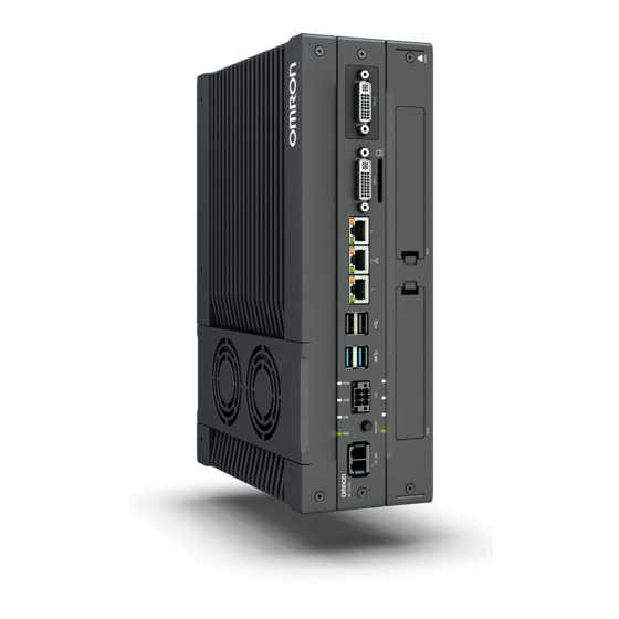
Omron AC1-152000 User Manual (230 pages)
IPC Application Controller
Brand:
Omron
| Category:
Controller
| Size: 8 MB
Table of Contents
Introduction
3
Intended Audience
3
Applicable Products
3
Sections in this Manual
5
Table of Contents
6
Manual Information
11
Page Structure
11
Special Information
12
Terms and Conditions Agreement
13
Warranty, Limitations of Liability
13
Application Considerations
14
Disclaimers
15
Safety Precautions
16
Definition of Precautionary Information
16
Symbols
16
Warnings
17
Cautions
19
Precautions for Safe Use
20
Disassembly, Dropping, Mounting, Installation and Storage
20
Wiring
20
Power Supply Design and Turning ON/OFF the Power Supply
21
Actual Operation
21
Operation
21
General Communications
22
Battery Replacement
22
Cleaning, Maintenance and Disposal
22
Precautions for Correct Use
23
Storage, Installation and Mounting
23
Wiring
23
Actual Operation and Operation
24
Battery Replacement
24
SD Memory Cards
24
Regulations and Standards
25
Conformance to EU Directives
25
Conformance to KC Certification
26
Conformance to UL and CSA Standards
26
Software Licenses and Copyrights
26
Related Manuals
27
Related Products Manuals
27
Related Application Controller Manuals
27
Industrial Monitor Manual
28
Terminology and Abbreviations
29
Industrial PC Platform
29
Hardware
29
Software
30
Revision History
31
Overview
34
Intended Use
34
Hardware Features
35
ID Information Label Application Controller
36
Product Configuration
37
Layers and Components
40
Cooling Layer
41
Base Layer
42
Expansion Layer (Optional)
43
LED Indicators
44
PWR LED Indicator
44
ERR LED Indicator
45
HDD LED Indicator
45
RUN LED Indicator
45
Power Button
46
Connectors
47
Power Connector
47
I/O Connector
47
USB Connectors
48
Ethernet Connectors
49
DVI Connector
49
RS-232C Connector (Optional)
50
Pcie Poe Connectors
50
SD Memory Card Slot
51
Drive Bays
52
Pcie Poe Card Slot
53
Spare Parts
54
Battery
54
Fan Unit
54
Accessory Kit
55
Optional Hardware
56
Mounting Brackets
56
SD Memory Cards
56
USB Flash Drives
57
HDD and SSD Storage Devices
58
DVI Cables
59
USB Type-A to USB Type-B Cables
59
Industrial Monitor
60
Power Supply
60
Ups
61
UPS Communication Cable
61
Software
63
Windows Operating System
64
Determine Your Version of the Windows Operating Systems
64
Ace
65
Support Software
66
Overview IPC Support Software for Windows
66
Installed IPC Support Software
67
Industrial PC Support Utility
68
Rescue Disk Creator
73
Industrial PC Tray Utility
80
Power Attendant Lite Utility
83
Specifications
87
General Specifications
88
Dimensions and Weight
88
General Electrical Specifications
89
Power Consumption Specifications
90
Power Supply Specifications
91
CPU Specifications
92
Memory Specifications
92
Storage Device Specifications
93
Bracket Specifications
95
Connector Specifications
97
Power Connector Specifications
97
I/O Connector Specifications
98
USB Connector Specifications
102
Ethernet Connector Specifications
103
DVI Connector Specifications
105
RS-232C Connector Specifications
106
Pcie Poe Connectors Specifications
107
Software Specifications
108
Available Windows Operating Systems
108
Supported Languages
108
Environmental Specifications
109
Operation Environment Specifications
109
Temperature and Humidity Specifications
110
Recycling Specifications
112
Installation
113
Unpack
114
Unpack Procedure
114
Items Supplied
114
Install Options
117
Install a Drive
117
Mount
121
Installation Method in Control Panels
121
Product Orientation
122
Temperature
122
Humidity
125
Vibration and Shock
125
Atmosphere
126
Electrical Environment
126
Book Mount Procedure
131
Wall Mount Procedure
132
Wire
133
Wiring Warnings and Cautions
133
Ground
133
Wire the Power Connector
140
Wire the I/O Connector
143
Connect
146
Connector Identification
146
Connection Procedure
147
Initial Power on
149
Initial Power on Procedure
149
Windows Startup First Time
151
Install Software
153
Firewall
153
Anti-Virus Software
153
Drivers and Custom Software
154
Activate Windows
154
Connect UPS
155
Connect UPS Using the USB Connector
156
Connect UPS Using the I/O Connector
158
Create Backup and Repair Media
161
Power on
164
Power on Using the Power Button
164
Power on Using the Power ON/OFF Input
164
Auto Power on
164
Power off
165
Power off Using the Power Button
165
Power off Using Windows Shut down
165
Power off Using the Power ON/OFF Input
166
Forced Power off Using the Power Button
166
Unified Write Filter
167
Enable Unified Write Filter
168
Disable Unified Write Filter
169
Determine Status Unified Write Filter
170
Install and Update Software
171
React to Product Messages
172
React to Windows Messages
173
Preventive Maintenance
176
Preventive Maintenance Schedule
176
Clean the IPC
177
Keep Software Updated
177
Create Backup and Repair Data
178
Check the Backup and Repair Media
188
Corrective Maintenance
189
Warning and Error Messages
189
Remove the Cover
191
Replace the Fan Unit
192
Replace the Battery
194
Replace a Drive
196
Restore and Repair Data
201
Allocate a Drive in Windows
211
Windows Event Viewer
212
Windows Low on Memory
214
Windows Blue Screens
215
A-1 Bios
218
A-1-1 BIOS Overview
218
BIOS Overview
218
BIOS for 7 Th Generation Cpus
220
A-2 Customize Windows
223
A-2-1 Trusted Platform Module
223
Trusted Platform Module
223
A-3 RS-232C Connector Pin Details
224
A-4 DVI Connector Pin Details
225
A-4-1 DVI-I Connector Pin Details
225
DVI-I Connector Pin Details
225
Advertisement
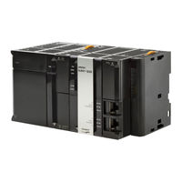
Omron AC1-152000 Startup Manual (168 pages)
Machine Automation Controller, Robot Integrated System
Brand:
Omron
| Category:
Controller
| Size: 20 MB
Table of Contents
Intended Audience
3
Applicable Products
3
Relevant Manuals
5
Manual Structure
7
Page Structure
7
Special Information
8
Precaution on Terminology
8
Sections in this Manual
9
Table of Contents
10
Terms and Conditions Agreement
13
Warranty, Limitations of Liability
13
Application Considerations
14
Disclaimers
14
Safety Precautions
16
Definition of Precautionary Information
16
Symbols
16
Warning
17
Cautions
17
Precautions for Safe Use
18
Precautions for Correct Use
19
Regulations and Standards
20
Versions
21
Checking Versions
21
Related Manuals
24
Relevant Technical Guides
27
Terminology
28
Revision History
29
Overview
31
Features of Robot Integrated System
32
Features of the NJ-Series Robot Integrated CPU Unit
32
Features of the Ethercat-Compatible OMRON Robots
32
Features of the Sysmac Studio Automation Software
32
System Configuration for Static Pick-And-Place Equipment
33
Operations of Static Pick-And-Place Equipment
35
Operating Specifications
35
Operating Modes for Equipment
36
Hardware
37
Software
38
Sysmac Studio
38
User Program
39
Types of Method to Create User Program
39
Proper Use of Sequence Control Program and V+ Program
39
Command and Data Flow
40
Installing the Sysmac Studio
44
Installing and Wiring the System
45
Wiring the Robot Integrated CPU Unit and the Ethercat Digital I/O Terminal
45
Setting the Node Address of the Ethercat Digital I/O Terminal
46
Wiring the Ethercat Digital I/O Terminal and the Robot
46
Setting the Ethercat Node Address of the Robot
47
Wiring the Robot Integrated CPU Unit and the Computer
47
Wiring the Robot, T20 pendant and the Front Panel
47
Wiring the Ethercat Digital I/O Terminal and the Solenoid Valve
49
Implementation Example of Static Pick-And-Place Equipment
51
Program Specifications for Static Pick-And-Place Equipment
52
When Operations Are Controlled with Sequence Control Program
53
When Operations Are Controlled with V+ Program
61
Basic Startup Procedures
67
Programming and Simulation Procedures
68
Creating a Project File
68
Creating the Ethercat Network Configuration
69
Creating a Sequence Control Program
72
Creating V+ Programs
82
Placing 3D Shape Data
84
Starting Simulation
106
Teaching Positions
107
Setting up Automatic Loading of V+ Programs and Variables at Power on
117
Running the Program and Checking Operation
120
Setup Procedure for Actual System
125
Connecting Online
125
Transferring Settings and Programs
127
Teaching
130
Executing Program to Check Operation
141
Appendices
145
Designing Example of the Safety Functions for the Pick-And-Place Equipment
146
Designing Example of the Safety Functions for the Pick-And- Place Equipment
146
A-1-1 Pick-And-Place Equipment Configuration
146
Pick-And-Place Equipment Configuration
146
A-1-2 Hazards
148
A-1-3 Protective Measure
148
A-1-4 Safety Functions
148
A-1-5 Safety System Configuration and Devices
149
A-1-6 Installation and Wiring
151
A-1-7 Settings and Programming
157
Setting Items on the Sysmac Studio and the Setting Targets
165
Using Troubleshooting Functions
166
Advertisement
Related Products
OMRON ACCURAX-G5 - 2
OMRON ACCURAX G5 SERVO MOTORS
OMRON SENSOR ACCESSORIES
Omron Accurax G5 Series
Omron E5CN-QMTC-500 AC/DC24 E5CN-QMP-500 AC/DC24 E5CN-R2MTC-500 AC/DC24 E5CN-R2MP-500 AC/DC24 E5CN-Q2MTC-500 AC/DC24 E5CN-Q2MP-500 AC/
OMRON A3CT-90A1-28
Omron A22NZ-BPM-UOA
Omron A22NZ-BMA-URA
Omron A22NZ-RPA-NRA
Omron A22NZ-RNA-URA
Omron Categories
Blood Pressure Monitor
Controller
Accessories
Switch
Inverter
More Omron Manuals
Login
Sign In
OR
Sign in with Facebook
Sign in with Google
Upload manual
Upload from disk
Upload from URL