Advertisement
Quick Links
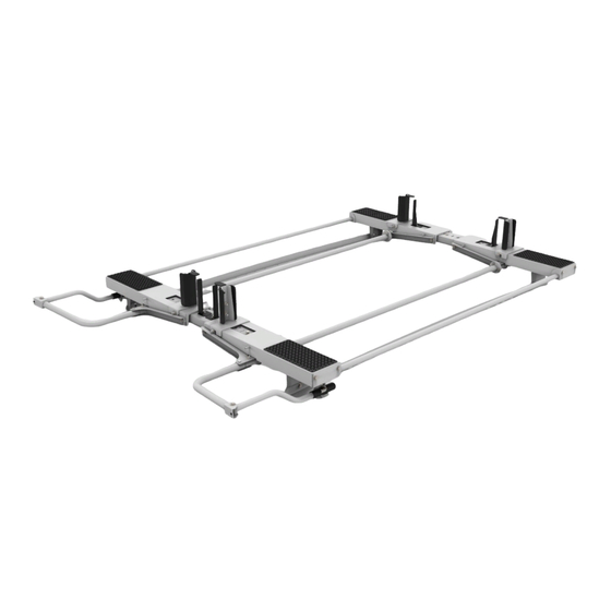
Front Ladder Pan Assy. (1) Rear Ladder Pan Assy. (1)
Latch(1) Ladder Hook(2 Ladder Stop(2) Dampener MntBrkt(2) Roller(4) Axle(2) Dampener(1)
No Dampener Mnt Brackets in 40943
40963/40943 Parts List
Front Torque Tube Pivot Assy. Rear Torque Tube Pivot Assy.
Ladder Pan Stiffener (1)
Torque Tube (1)
Handle Assy. (1)
1
Advertisement

Related Manuals for Kargo Master 40963


Summary of Contents for Kargo Master 40963
- Page 1 40963/40943 Parts List Front Torque Tube Pivot Assy. Rear Torque Tube Pivot Assy. Front Ladder Pan Assy. (1) Rear Ladder Pan Assy. (1) Latch(1) Ladder Hook(2 Ladder Stop(2) Dampener MntBrkt(2) Roller(4) Axle(2) Dampener(1) No Dampener Mnt Brackets in 40943 Torque Tube (1) Ladder Pan Stiffener (1) Handle Assy. (1) 1 ...
-
Page 2: Tools Needed
40963 40943 Harware List Tools Needed 8' Tape Measure 1/4" End Wrench 1/4" Socket 5/16" End Wrench 5/16" Socket Hammer Hardware Pack Qty 2 - 5/16"-18 x 3/4" Carriage Bolt Qty 10 - 5/16" Flat Washer ( c) Qty 4 - 5/16"... - Page 3 40963/40943 Installation Instructions Step 1 Bolt “Dampener mounting bracket” underneath the crossbow (both front and rear) as shown below using 3/8”x3/4 Bolts with flat and lock washers. Step 2 Bolt “Torque tube pivot Assy.” underneath the crossbow (both front and rear) as shown below using 3/8”x3/4 Bolts with flat and lock washers. Be sure to have the 3 hole flanges facing each other (rear bow shown). You may need to detach the feet and lift the crossbow slightly to get into place. Step 3 Attach the “Torque Tube” between the flanged plates on the “Torque Tube pivot Assy.” Using ¼”x7/8” bolts as shown below. Be sure the “Torque Tube pivot Assy.” are lined up prior to bolting them together. You can now re‐attach the feet. (j) (k) (l) 2 ...
- Page 4 Step 3 continuned. Step 4 Next attach the “Dampener” to the rear bow assembly. Make sure the “Torque Tube Pivot Assy.” is rotated so the cam is pointed towards the center of the van. Attach the shaft end of the “Dampener” to the cam using the 5/16” pin, make sure the cotter pin is secure. Now attach the body end to the “Dampener mounting Bracket” using the 5/16”x2 1/4” pin, sandwich the nylon spacer (p) to secure the dampener in the middle of the bracket. Dampener Nylon Spacer 3 ...
- Page 5 Step 5 Attach the “Latch” To the rear bow assy. as shown below using 5/16”x3/4” carriage bolts(a) with flat washers(b) and nylock nuts(d). (a) (b) (d) Step 6 Next install the “Axles” and “Rollers” at the end of both front and rear crossbow. The “Axle” just slides in and the “Rollers” slide over the ends of the “Axle” as shown below, make sure insert the nylon washers(n) between the wheels and crossbow. (n) (n) Step 7 Next install the “Ladder Pan Assy.” Align cutouts in “Ladder Pan Assy.” with the “Rollers” and guide the arms onto the “Torque Tube Pivot Assy.” As you lower the assembly onto the rollers. Insert 5/16”x 2” bolts with flat washer and nylock nuts through arms and “Torque Tube Assy.” Make sure the “Rear Ladder Pan Assy.” is on the rear crossbow. 4 ...
- Page 6 Step 8 Install handle assembly, use E6000 on 5/16”x 2” bolts to keep water out of the tube. Be sure handle will clear the back of the van. 5 ...
- Page 7 Step 9 Attach ladder pan stiffener, in the closed position, using 5/16”x5/8” bolts(e)with lock washers(c) and flat washers(b).‐ (c) (b) (e) 6 ...
- Page 8 Step 10 Attach ladder hooks to ladder pans on 5/16” studs in desired location(Diagram A). Attach ladder stops to coincide with ladder hooks by removing 3/8”x3/4” bolt and placing stop so the tab on the stop goes into the corresponding slot.The diagram below shows in the lower position commonly used for extension ladders. You can install in the upper position in the rear for step ladders (as shown in last view). 7 ...
- Page 9 Installation Complete for Extension Ladder Installation Complete For Step Ladder 8 ...
Need help?
Do you have a question about the 40963 and is the answer not in the manual?
Questions and answers