
Subscribe to Our Youtube Channel
Related Manuals for KSB Delta Basic MVP


Summary of Contents for KSB Delta Basic MVP
- Page 1 Pressure Booster System KSB Delta Basic KSB Delta Basic MVP Installation/Operating Manual...
- Page 2 Subject to technical modification without prior notice. © KSB B.V., Alphen aan den Rijn, Nederland 01/08/2019...
-
Page 3: Table Of Contents
Fitting an expansion joint (optional).................... 20 5.3.2 Fitting the pressure reducer (optional) .................... 21 Mounting the accumulator.......................... 21 Connecting the dry running protection device .................... 22 Electrical connection ............................ 22 5.6.1 Sizing the power cable ........................ 23 5.6.2 Connecting the pressure booster system.................. 23 KSB Delta Basic 3 of 48... - Page 4 Mounting the manifold in a mirrored position ................ 34 Trouble-shooting.......................... 38 Related Documents .......................... 40 10.1 General assembly drawings/exploded views with list of components ............ 40 10.1.1 KSB Delta Basic MVP .......................... 40 EU Declaration of Conformity ...................... 41 Certificate of Decontamination...................... 42 Commissioning Report......................... 43 Index ..............................
-
Page 5: Glossary
Efficiency class to IEC 60034-30: 3 = Premium Efficiency (IE = International Efficiency) Switchgear and controlgear assembly Control cabinet with one or several control units / switchgears and electrical equipment. KSB Delta Basic 5 of 48... -
Page 6: General
The serial number uniquely describes the product and is used as identification in all further business processes. In the event of damage, immediately contact your nearest KSB service facility to maintain the right to claim under warranty. 1.2 Software changes The software has been specially created for this product and thoroughly tested. -
Page 7: Key To Safety Symbols/Markings
In conjunction with one of the signal words this symbol indicates a hazard involving electrical voltage and identifies information about protection against electrical voltage. Machine damage In conjunction with the signal word CAUTION this symbol indicates a hazard for the machine and its functions. KSB Delta Basic 7 of 48... -
Page 8: Safety
2.2.1 Prevention of foreseeable misuse ▪ Never exceed the permissible application and operating limits specified in the product literature regarding pressure, temperature, etc. ▪ Observe all safety information and instructions in this manual. KSB Delta Basic 8 of 48... -
Page 9: Personnel Qualification And Personnel Training
▪ Carry out work on the pressure booster system during standstill only. ▪ The pump casing must have cooled down to ambient temperature. ▪ Pump pressure must have been released and the pump must have been drained. KSB Delta Basic 9 of 48... -
Page 10: Unauthorised Modes Of Operation
The following limit values and inspection/test levels must be complied with if the generic standard on interference emissions applies: An EMC plan must be devised. KSB Delta Basic 10 of 48... -
Page 11: Line Harmonics Requirements
▪ EN 61000-4-5: Electromagnetic compatibility (EMC) – Part 4-5: Testing and measurement techniques – Surge immunity test ▪ EN 61000-4-6: Electromagnetic compatibility (EMC) – Part 4-6: Testing and measurement techniques – Immunity to conducted disturbances, induced by radio-frequency fields KSB Delta Basic 11 of 48... -
Page 12: Transport/Temporary Storage/Disposal
1. On transfer of goods, check each packaging unit for damage. 2. In the event of in-transit damage, assess the exact damage, document it and notify KSB or the supplying dealer and the insurer about the damage in writing immediately. -
Page 13: Return To Supplier
2. Separate and sort the pump materials, e.g. by: - Metals - Plastics - Electronic waste - Greases and other lubricants 3. Dispose of materials in accordance with local regulations or in another controlled manner. KSB Delta Basic 13 of 48... - Page 14 Contact your local waste disposal partner for returns. If the used electrical or electronic equipment contains personal data, the operator is responsible for deleting it before the equipment is returned. KSB Delta Basic 14 of 48...
-
Page 15: Description
4 Description 4 Description 4.1 General description ▪ Pressure booster system 4.2 Designation Example: KSB Delta Basic 3/1004 MVP Table 8: Designation key Code Description KSB Delta Basic Type series Number of pumps Size Number of stages Design Variable speed pressure booster system 4.3 Name plate... -
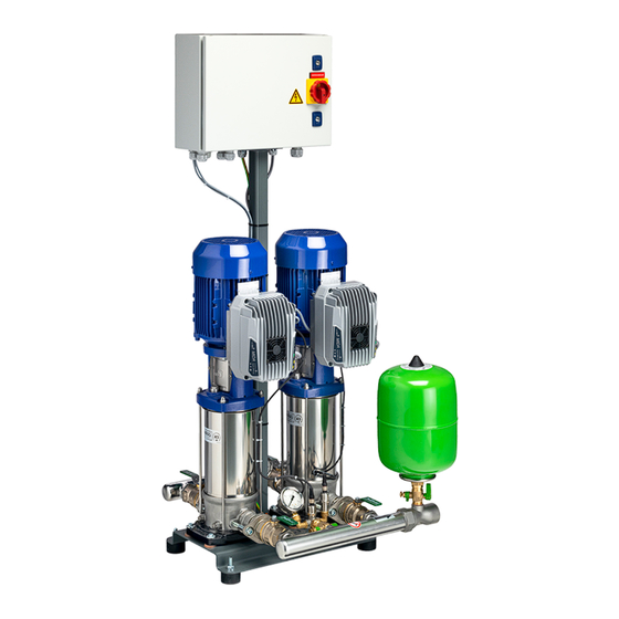
Page 16: Configuration And Function
▪ Control unit (IP54 enclosure) ▪ Fault message signalling contact per pump ▪ Operation signalling contact per pump 4.5 Configuration and function Fig. 2: Illustration of pressure booster system Control cabinet Pump Control unit Membrane-type accumulator Manifold Baseplate KSB Delta Basic 16 of 48... -
Page 17: Noise Characteristics
Example Pressure booster system with 4 pump sets (value: + 6 dB(A)) Single pump = 48 dB(A) 48 dB(A) + 6 dB(A) = 54 dB(A) The expected total sound pressure level of 54 dB(A) may develop when all 4 pump sets are running under full-load conditions. Multiple pump systems only KSB Delta Basic 17 of 48... -
Page 18: Scope Of Supply
For the terminal assignment refer to the circuit diagram. 4.10 Potential equalisation A terminal marked with the earth symbol is provided at the power connection for connecting a PE conductor. Fig. 3: PE connection Earthing terminal Location of power connection KSB Delta Basic 18 of 48... -
Page 19: Installation At Site
The anti-vibration mounts of the pressure booster system provide adequate insulation against solid-borne noise. Thanks to level-adjustable feet (KSB accessory) the pressure booster system can also be installed in a horizontal position on uneven floors. For pressure booster systems with pumps, Movitec 2, 4, 6, 10, 15 level-adjustable feet are available as accessories. -
Page 20: Connecting The Piping
3. Connect the piping to the distribution lines on the inlet side and discharge side. 5.3.1 Fitting an expansion joint (optional) DANGER Sparks and radiant heat Fire hazard! ▷ Take suitable precautions to protect the expansion joint if any welding work is carried out. KSB Delta Basic 20 of 48... -
Page 21: Fitting The Pressure Reducer (Optional)
▷ Clean the accumulator before filling it. ü The original operating manual of the pressure booster system is on hand. 1. Mechanically and electrically connect the accumulator in accordance with the original operating manual supplied. KSB Delta Basic 21 of 48... -
Page 22: Connecting The Dry Running Protection Device
When ordering spare parts for electrical components, always indicate the number of the wiring diagram. Terminal assignment For the terminal assignment refer to the wiring diagram. KSB Delta Basic 22 of 48... -
Page 23: Sizing The Power Cable
2. Connect the potential equalisation conductor on the baseplate to the terminal with the earthing symbol. Fig. 5: Connecting the potential equalisation conductor 1 Earthing terminal 2 Baseplate For accessories and/or integrated machinery components, observe the relevant manufacturer's product literature. KSB Delta Basic 23 of 48... -
Page 24: Commissioning/Start-Up/Shutdown
For extensive or branched piping systems, flushing the pressure booster system can be restricted to a limited area. Commissioning should be carried out by specialist KSB staff. CAUTION Foreign matter in the piping Damage to the pump / pressure booster system! ▷... -
Page 25: Switching On The Pressure Booster System
6.2 Switching on the pressure booster system Plug in the mains plug or set the master switch to I to energise the pump. Readiness for operation is signalled by a permanently lit red LED and a flashing green LED. KSB Delta Basic 25 of 48... -
Page 26: Checklist For Commissioning/Start-Up
ð The pressure booster system is being vented and drained. 2. Re-tighten vent plug 1 on the accumulator. 6.4.2 Shutdown Standard design 1. Set the master switch to 0. Additional instruments 1. Set manual-0-automatic selector switch to 0. KSB Delta Basic 26 of 48... -
Page 27: Operating The Pressure Booster System
7.1 Design of the frequency inverter The frequency inverter is motor-mounted and self-cooling. Its display and control panel feature the following: Fig. 7: KSB Delta Compact display and control panel Red LED indicating stand-by The red stand-by LED is lit when the motor is energised. - Page 28 ▪ If the Set LED (5) flashes, press the Plus button or Minus button until the Set LED lights up continuously. ▪ Set the pressure by pressing the Plus button or Minus button as required. KSB Delta Basic 28 of 48...
-
Page 29: Servicing/Maintenance
Function of pressure booster system not guaranteed! ▷ Regularly service the pressure booster system. ▷ Prepare a maintenance schedule for the pressure booster system, with special emphasis on lubricants, shaft seals and pump couplings. KSB Delta Basic 29 of 48... -
Page 30: Inspection Contract
▪ For any work on the pump (set) observe the operating manual of the pump (set). ▪ In the event of damage you can always contact KSB Service . ▪ A regular maintenance schedule will help avoid expensive repairs and contribute to trouble-free, reliable operation with a minimum of maintenance expenditure and work. -
Page 31: Setting The Pre-Charge Pressure
5. Fit the protective cap of the membrane-type accumulator valve. Filling the membrane-type accumulator 1. Remove and store the protective cap of the membrane-type accumulator valve. 2. Add nitrogen through the valve. 3. Fit the protective cap of the membrane-type accumulator valve. KSB Delta Basic 31 of 48... -
Page 32: Replacing The Non-Return Valve
6. Use a suitable tool to screw the body parts of the non-return valve into each other to shorten the length of the body. Fig. 10: Removing the body 7. Remove the body of the non-return valve. KSB Delta Basic 32 of 48... - Page 33 12. Use a suitable tool to loosen the screwed connection of the body parts of the non-return valve to extend the body length. Fig. 13: Verifying the alignment 13. Verify the correct alignment. Fig. 14: Fitting the screw KSB Delta Basic 33 of 48...
-
Page 34: Mounting The Manifold In A Mirrored Position
3. Place a suitable container under the drain connections. 4. Open the drain connections. To do so, observe the pump's operating manual. Fig. 15: Removing the bolts 5. Remove the tie bolts between the two oval flanges and the pumps. Sealant for taps KSB Delta Basic 34 of 48... - Page 35 EF locknut 7. Undo the EF locknut at both shut-off valves by half a turn. The O-ring is now exposed. Fig. 18: Turning the pressure measuring set Pressure measuring set Lever of the shut-off valve KSB Delta Basic 35 of 48...
- Page 36 10. Turn the shut-off valves by 180°. Then turn the manifold with shut-off valves by 180°. Fig. 20: Turning the pressure measuring set Pressure measuring set 11. Turn the pressure measuring set by a last 90°. KSB Delta Basic 36 of 48...
- Page 37 12. If the pressure gauge and/or pressure sensors have been removed, connect them again. ð The manifold is now fitted in a mirrored position. 13. Tighten the EF locknuts of the shut-off valves again. KSB Delta Basic 37 of 48...
-
Page 38: Trouble-Shooting
Increase flow rate of in suction line too low water meter. System-side filter clogged Clean filter or check filter for obstruction. If required, replace filter. Shut-off valve in outlet Open both shut-off and/or inlet closed valves. KSB Delta Basic 38 of 48... - Page 39 The alarm value for minimum pressure has been reached. (Determine the cause of the minimum pressure falling below the alarm value). Rapid flashing The digital inputs have been disconnected. without any pauses KSB Delta Basic 39 of 48...
-
Page 40: Related Documents
10 Related Documents 10 Related Documents 10.1 General assembly drawings/exploded views with list of components 10.1.1 KSB Delta Basic MVP 79-2 743.90 743.90 742.02 742.01 743.90 Fig. 21: KSB Delta Basic MVP Table 16: List of components Part No. Description Part No. -
Page 41: Ksb Delta Basic Mvp
2401 LJ Alphen aan den Rijn (The Netherlands) The manufacturer herewith declares that the product: KSB Delta Basic MVP Serial number: 06/2018 0000000-0001 - 52/2020 9999999-9999 ▪ is in conformity with the provisions of the following Directives as amended from time to time: –... -
Page 42: Certificate Of Decontamination
We confirm that the above data and information are correct and complete and that dispatch is effected in accordance with the relevant legal provisions....................................Place, date and signature Address Company stamp Required fields KSB Delta Basic 42 of 48... -
Page 43: Commissioning Report
13 Commissioning Report 13 Commissioning Report The pressure booster system specified below has been commissioned today by the undersigned, authorised KSB Service who created this report. Pressure booster system details Type series ............................Size ............................Serial number ............................Order No. -
Page 44: Index
Event of damage 6 Installation 16 Installation at site 19 Intended use 8 Interference emissions 10 Key to safety symbols/markings 7 Maintenance work 30 Operating limits 8 Other applicable documents 6 Partly completed machinery 6 Personnel 9 Qualification 9 Return to supplier 13 Safety 8 Safety awareness 9 Scope of supply 18 KSB Delta Basic 44 of 48... - Page 48 KSB B.V. Kalkovenweg 13 2401 LJ Alphen aan den Rijn (Netherlands)
Need help?
Do you have a question about the Delta Basic MVP and is the answer not in the manual?
Questions and answers