Table of Contents
Advertisement
Operating instructions
1384.8/4--10
These operating instructions contain fundamental information and precautionary notes.
Please read the manual thoroughly prior to installation of unit, electrical connection and
commissioning. It is imperative to comply with all other operating instructions referring to
components of individual units.
Any work on the unit must only be carried out with the electrical connections (incl. control cable)
disconnected (or unplugged). Make sure that the pump set cannot be switched on accidentally.
Ident--No.:
01 059 616
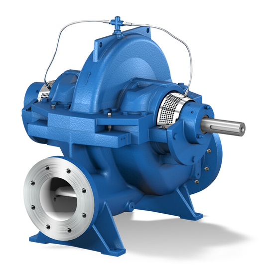
Omega
Volute casing pump
with radial impeller
Pump set
Horizontal installation -- 3 E
Advertisement
Chapters
Table of Contents

Related Manuals for KSB Omega Series


Summary of Contents for KSB Omega Series
- Page 1 Omega Operating instructions 1384.8/4--10 Volute casing pump with radial impeller Pump set Horizontal installation -- 3 E These operating instructions contain fundamental information and precautionary notes. Please read the manual thoroughly prior to installation of unit, electrical connection and commissioning. It is imperative to comply with all other operating instructions referring to components of individual units.
- Page 2 Omega For usage in hazardous locations refer to supplementary operating instructions 1387.81.
-
Page 3: Table Of Contents
Omega Contents Page General ................Safety . -
Page 4: General
Omega General The word This KSB pump has been developed in accordance with Caution state- -of- -the- -art technology; it is manufactured with ut- most care and subject to continuous quality control. is used to introduce safety instructions whose non--observance These operating instructions are intended to facilitate familiari- may lead to damage to the machine and its functions. -
Page 5: Safety Instructions For The Operator / User
Omega Transport and Interim Storage Safety Instructions for the Operator / User · Any hot or cold components that could pose a hazard must be equipped with a guard by the operator. Transport · Guards which are fitted to prevent accidental contact with Transport of the unit requires proper preparation and handling. -
Page 6: Interim Storage / Preservation
Angle of pull > 90_ not permitted. Design Use two separate sets of lifting slings! The KSB pump of the Omega series is a horizontally installed, single--stage, axially split volute casing pump with double--en- try radial impeller. Connection flanges are manufactured accor- ding to EN, DIN, ISO, BS or ASME, as preferred. -
Page 7: Designation
Omega Designation Accessories (optional) Omega The following accessories are available: Configuration Omega Type series Accessories Fig.0 Discharge nozzle DN mm Motor ---- Nominal impeller dia. Baseplate/baseframe ---- Impeller type (A,B,C) Coupling and coupling guard ---- Design Details Sealing and flushing water pi- ping 4.3.1 Pump Casing... -
Page 8: Installing The Pump / Unit
Omega Installing the Pump / Unit Connecting the Piping Before setting up the pump, check the Never use the pump itself as an anchorage Caution Caution operating data. Ensure that the data on the point for the piping. name plate matches the data in the order and the system data, Suction lift lines shall be laid with a rising slope towards the e.g. -
Page 9: Commissioning, Start- -Up / Shutdown
Omega Commissioning, Start- -up / Correct direction of rotation: Shutdown The direction of rotation must correspond to the direction indi- cated by the arrow on the pump. This can be verified by swit- Compliance with the following requirements is Caution ching the pump on and then off again immediately. -
Page 10: Shutdown / Storage / Preservation
Shutdown / Storage / Preservation Pumps handling liquids posing health hazards must be Each KSB pump leaves the factory carefully assembled. If com- decontaminated. When draining the medium see to it missioning is to take place some time after delivery, we recom- that there is no risk to persons or the environment. -
Page 11: Maintenance / Inspection
Omega Maintenance / Inspection Dismantling and reassembly must always be carried out in ac- cordance with the relevant general drawing. The general dra- 7.2.1 Supervision of Operation wing and other relevant documents are found in the annex. The dismantling sequence can be derived from the general dra- The pump shall run quietly and free from Caution wing. -
Page 12: Reassembly
Omega Reassembly Reassembly is effected in reverse order to dismantling. For all work on the pump unit refer to the general drawing, in conjunc- tion with the list of components, for orientation. The rules of sound engineering practice and also the instruc- tions for removal and installation of shaft seal, bearings, impel- ler wear rings and casing wear rings (sections 7.5.1 and 7.5.2) must be observed. - Page 13 Omega O--rings and V--rings must be replaced and their seats on the Push the sleeve (520) with deep--groove ball bearing (321) onto shaft must be cleaned. In addition, all the sealing elements the pump shaft (211) with key (940.01) inserted. must be fitted into the respective components before installa- Tension the rotor parts elastically with keywayed nut (920) and tion.
-
Page 14: Instructions For Replacing Subassemblies
The impeller clearance clearance between impeller 234 and be turned off on a lathe (contact KSB before doing so) and an casing wear ring 502 is given in the table below. impeller wear ring fitted in addition (available as spare part). -
Page 15: Monitoring Schedule
Omega Monitoring schedule For a detailed description of the pump version, components and accessories supplied by KSB please refer to section 13 of this operating manual. Component monitored Action Value required Mechanical seal Check for leakage (daily) see section 8.2 and *... -
Page 16: Special Instructions For Subassemblies (Shaft Seal Variants)
It is approx. 10 to 120 drops per minute Gland packing (20 drops of water correspond to approx. 1 ml). The gland packings used by KSB are asbestos--free and suita- Disassembly ble for drinking water applications. A packing puller must be used for pulling out the packing rings. -
Page 17: Mechanical Seal Variants (Mech. Seal Size / Pump Size Combinations)
Omega Mechanical Seal Variants (Mech. Seal Size / Pump Size Combinations) Mechanical seal variants Pump size Shaft unit Nom. mech. seal Non- -balanced Balanced size for operating pres-- for operating pressures sures up to 16 bar > 16 bar 80 - 210 80 - 270 80 - 370 M 7 N 4 / 50... - Page 18 Omega 8.2.1 Mechanical Seal ”Type H7N4” (Shaft unit d 40 to 80 mm) The mechanical seal type H 7 N 4 used is a single--acting, bi--ro- tational, non--balanced seal which does not require circulation pipework in cold water applications, due to the pump design. Dry- -running of the seal must be avoided at Caution all costs!
- Page 19 (e.g. heating). If repair on the spot is necessary, it should be carried out in a clean workshop preferrably by KSB--monteurs or skilled opera- Should the mechanical seal fail, the liquid to be sealed off may tor staff.
- Page 20 Omega 8.2.2 Mechanical Seal - - ”Type M74N ” The seat ring (8) together with the relevant O--ring (9), is fitted (Shaft unit d = 90 mm) into the seal cover (see general drawing). The O--ring can be lubricated for easy sliding movement. Special attention must This mechanical seal type is a single- -acting, bi- -rotational, be given to ensure that pressure is applied evenly.
- Page 21 KSB service cen- during pump start--up and shutdown. This must be ensured by tres.
- Page 22 Omega Mechanical seal removal 8.2.3 Mechanical Seal ”Type HJ92 N” (Shaft unit d = 40 to 80 mm) Shut down the pump in accordance with the operating manual, allow to cool down and release pump pressure. Note: There must be no pumped product at the Refer to sections 8.2.1 and 8.2.2 for general recommendations mechanical seal ®The pump must be drained.
- Page 23 OPERATING MANUAL MECHANICAL SEAL (MS) HJ92N PLEASE READ this manual carefully and OBSERVE the information contained as to: Safety Storage Installation Start up Maintenance Repair J SAFETY J OPERATING LIMITS Shaft diameter dw: 18 to 100 mm Any person in the operator’s plant who is involved in the installa- 25 bar Press.
- Page 24 Due to their protected spring (1.5), mechanical seals of this type The mechanical seals need not be preserved. are particularly suitable for fluids containing solids and/or highly D Do not apply anti--corrosives. viscous fluids, for ex. in sugar, paper or waste water applica- ' Risk of deposits and possible chemical attacks on ela- tions.
- Page 25 ' Double PTFE encapsulated O--rings must be fitted so that the joint of the outer sheath points in opposite direction to the mounting direction, so that the friction force generated when sliding on the O--ring closes the joint. Kinks in the foil will result in leakage.
- Page 26 If the fault/malfunction cannot be remedied by the operator or tion, which is described in the pump’s operating manual. if the cause is unclear, please contact your responsible KSB Removal of the mechanical seal shall be effected in analogy service centre.
- Page 27 Omega 8.2.4 Mechanical Seal –“Type H75N“ (Shaft unit dw = 90 mm) General instructions concerning assembly/installation, com- missioning, maintenance, faults and repair have already been given in sections 8.2.1 and 8.2.2. (See Operating manual from Type BURGMANN ) operating manual for seal type H75N).
- Page 28 OPERATING MANUAL BURGMANN MECHANICAL (M.S.) H75N PLEASE READ this manual carefully and OBSERVE the information contained as to: Safety Storage Installation Start up Maintenance Repair J SAFETY J OPERATING LIMITS Shaft diameter dw: 28 to 100 mm Any person in the operator’s plant who is involved in the installa- Press.
- Page 29 H Multiple springs in guide sleeves During storage, seal face materials and elastomers will un- H axial mobility/play up to dw 55 = ± 2 mm, and ± 3 mm dergo material specific time dependent changes (distortion, H Torque transmission by grub screws ageing), which can impair the perfect function of the mechanical H Connecting dimensions to DIN 24960 KB seal.
- Page 30 D Thread--locking compound, e.g. type ”LoctiteR Nr. 243”, Primary seal components producer: Loctite Corporation Spring--loaded ring D O--ring extractor Seat ring D Set of hex. keys (WAF 2 mm -- 6 mm) Secondary seal elements D Cardboard washers to protect the contact faces during in- O--ring (dynamic) stallation O--ring (static)
- Page 31 If the fault/malfunction cannot be remedied by the operator or tion, which is described in the pump’s operating manual. if the cause is unclear, please contact your responsible KSB Removal of the mechanical seal shall be effected in analogy service centre.
-
Page 32: Spare Parts
Omega Spare Parts Recommended Spare Parts Recommended spare parts stock for 2 years’ operation to VDMA 24296 (also for continuous operation) Part no. Description Number of pumps (incl. stand--by pumps) and more Number of spare parts * Impeller 30 % Casing wear ring 50 % Impeller wear ring... - Page 33 Omega Interchangeability of rotor components Pump sizes Pump shaft diameter 80 - 210 80 - 270 80 - 370 100 - 250 100 - 310 100 - 375 125 - 230 125 - 290 125 - 365 125 - 500 150 - 290 150 - 360 150 - 460...
-
Page 34: Forces And Moments
The values given in the table do not apply to the re- neous loading in the three planes. If the forces and moments in action forces of braceless expansion joints. one particular direction are larger than given in the table, con- sult KSB. Dimensions in mm Pump Impeller dimensions in mm... -
Page 35: Trouble- -Shooting
Omega Dimensions in mm Pump Impeller dimensions in mm Permissible nozzle Mass moments of Permissi- Permissi- sizes inertia ble opera- ble test ting pressure pressure free passage max. diameter Clearances forces moments (without coupling) in bar in bar in N in Nm in kgm ±... -
Page 36: Trouble--Shooting Table
Omega 11.2 Trouble- -shooting Table Cause Remedy Operating point B does not Re--adjust operating point lie at the calculated inter- sections of Q and H Pump or piping incomple- Vent. tely vented or not primed Suction pipe or impeller Clean impeller blocked Check plant for impurities Remove deposits in pump and / or piping... - Page 37 Unfavourable flow to suc- Alter piping tion nozzle of pump If necessary, alter intake pipe if resistances are too high Check whether pipe routing results in twi- sted or irregular flow (e.g. downstream of an elbow) and correct, if necessary. ) Consult KSB...
- Page 38 Re--balance rotor. Bearings damaged Replace / change Flow rate too low Re--adjust operating point Fully open shut--off valve in the intake pipe Fully open shut--off valve in the discharge pipe Recalculate or measure the hydraulic los- ses H ) Consult KSB...
- Page 39 Alter pump characteristic H Shaft is out of true Renew / Replace Impeller rubs against ca- Check rotor sing components Check impeller position Check that the piping is connected wi- thout transmitting any stresses or strains. ) Consult KSB...
-
Page 40: Routine Maintenance And Inspection Intervals
Omega Routine Maintenance and Inspection Intervals Interval Number of per- Time Maintenance job sonnel required Check leakage on mechanical seal or lea- kage of packed gland Daily 1/10 (see section 8.1 ”Gland packing”). Check pump operation (positive suction pres- Weekly sure, total head, bearing temperature, noises and vibrations) Check torsional play of coupling... -
Page 41: Appendix
Omega Appendix Contents ................. . . Page Types of installation . -
Page 42: Types Of Installation
Omega Types of installation Horizontal Type of installation 3E Pump set with close- -coupled motor (type IM B3) Baseplate, baseframe, coupling guard and motor height adjustment Vertical Type of installation DB Type of installation DK Type of installation DJ Version with intermediate bearing Depending of motor size Direction of rotation / flow direction Horizontal... -
Page 43: Type Of Installation 3E - - Motor Height Adjustment
Omega Type of Installation 3E - - Motor Height Adjustment Baseplate with adjusting screw or shims under the motor feet 901.54 550.54 89-4.54 (Shims) (840) (681) 550.55 901.06 909.54 550.56 (Adjusting screw) 901.05 89--4.03 for screw set without adjusting screw (909.54) 920.10 550.10 900.01... -
Page 44: Type Of Installation 3E -- Motor Height Adjustment -- Baseframe With Base / Shims Under The Motor Feet
Omega Type of Installation 3E - - Motor Height Adjustment - - Baseframe with Base / Shims under the Motor Feet 901.54 (902.54) (920.54) 550.54 901.06 89-4.54 (Shim) 550.56 (592.54) (Base) 901.05 optional, depending on height required for long lengths, instead of hex. head bolts 89--4.03 920.10 550.10... -
Page 45: Sealing / Flushing Water Piping
Omega Sealing / flushing water piping The pump is equipped with sealing / flushing water piping. These pipes are sheathed PTFE hoses which are flexible, tem- perature and highly pressure resistant. Another favourable property of PTFE (polytetrafluorethylene) is the extremely low friction coefficient which prevents pipe clogging. -
Page 46: Sealing Water Pipe For Gland Packing
Omega Sealing water pipe for gland packing 903.01 731.03 731.04 719.01 731.02 (731.12) (731.11) 731.05 Part no. Description 719.01 Flexible tube 731.02 Nipple joint 731.03 Cross 731.04 Nipple joint 731.05 Pipe bend 731.12 Socket 903.01 Screwed plug Sealing water pipe for mechanical seal 903.01 731.03 731.04... -
Page 47: Coupling (N- -Eupex)
Omega Coupling (N- -EUPEX) Installation - - Design of types A / ADS (Flexible couplings N- -EUPEX and N- -EUPEX- -DS, types A and ADS) The N--EUPEX coupling types A / ADS consist of a coupling part 1 which houses the flexible coupling blocks (12), the finger ·... - Page 48 Omega Heating up the coupling parts (to max. +150 °C) may facilitate Using a dial micrometer will make for increased measuring ac- pulling on the coupling parts. If temperatures exceed +80 °C, curacy. the flexible coupling blocks must be removed from the coupling To allow one shaft end to rotate freely, the driving section can parts before the heating process.
-
Page 49: Correlation Between Tightening Torques, Dimension P And Clearance S1
Omega Correlation between tightening torques, dimension P and clearance S N-EUPEX N-EUPEX-DS Tightening torque T and width across flats S for bolts to DIN 912 Part 2/3 coupling coupling Size Size [mm] [mm] [mm] 17,5 67,5 5-10 5-10 5-10 ---- 6-12 ---- 1450... -
Page 50: Trouble--Shooting
Omega Trouble- -shooting General Before commencing any maintenance, repair or other work on the coupling, the operator must shut The faults listed below shall serve as orientation only when de- down the entire driving mechanism. The drivers, in parti- termining failure causes. cular, must be secured against inadvertent start- -up. - Page 51 Omega Table: Wear mark on N- -EUPEX coupling Size Wear mark 10.0 11.5 10.5 11.5 13.0 14.0 15.5 17.5 17.5 19.5 21.0 22.5 Table: Wear mark on N- -EUPEX- -DS coupling Size wear mark 10.5 11.5 8.0 6.5 7.0 10.0 12.0 14.0 16.0...
-
Page 52: General Drawing Of Pump With Parts List Shaft Seal: Gland Packing
Omega General drawing of pump with parts list Shaft seal: Gland packing Shaft Axial overhang of shaft protec- diameter ting sleeve Sealed with Loctite 574 A ± 0.5 ALTEMP Q NB 50 grease... - Page 53 Omega Part no. Description Part no. Description Part no. Description Volute casing Gland cover Grooved pin 105.01 Lower casing half Gland packing 105.02 Upper casing half Stuffing box insert Hex. head bolt Pump shaft Neck ring Stud Impeller Lantern ring Screwed plug Deep--groove ball bearing Casing wear ring...
-
Page 54: General Drawing Of Pump With Parts List Shaft Seal: Mechanical Seal
Omega General drawing of pump with parts list Shaft seal: Mechanical seal Shaft Axial overhang of shaft protec- diameter ting sleeve Sealed with Loctite 574 A ± 0.5 ALTEMP Q NB 50 grease... - Page 55 Omega Part no. Description Part no. Description Part no. Description Volute casing Radial shaft seal ring Hex. head bolt 105.01 Lower casing half Mechanical seal Screwed plug 105.02 Upper casing half Housing for shaft seal Pump shaft 457.02 Stuffing box insert Circlip Impeller Impeller wear ring...
-
Page 56: Mechanical Seals, Standard Design
Omega Mechanical seals, standard design Standardized mechanical seal to DIN 24960 - - short design, non- -balanced Sizes for shaft diameter d = 40 to 80 mm (with single spring) 524.01 457.02 525.02 901.16 Flushing line connection Standardized mechanical seal to DIN 24960 - - short design, non- -balanced Sizes for shaft diameter d = 90 mm (with multiple spring arrangement) 524.01... - Page 57 Omega Mechanical seals, standard design Balanced mechanical seal (for operating pressures > 16 bar) to DIN 24960 Sizes for shaft diameter d = 40 to 80 mm (with covered spring) 457.02 901.16 Flushing line connection 525.02 524.01 Balanced mechanical seal (for operating pressures p > 16 bar) to DIN 24960 Sizes for shaft diameter d = 90 mm (with multiple spring arrangement) Flushing line...
-
Page 58: Shaft Seal - - Mechanical Seals - - Type Crane 58U And 58B
Omega Shaft seal - - mechanical seals - - Type Crane 58U and 58B Description Preparation for installation The mechanical seals, 58U and 58B, are precision--made and 1. The installation dimensions and tolerances must comply must be treated accordingly. The contact faces are lapped to with those outlined in the relevant literature. - Page 59 Omega Dismantling and assembly of the rotating unit The first step is to remove the snap ring (096) from the retainer (780). The springs are compressed to achieve this. This can be done by using a simple tool, as illustrated. Lapped surfaces of the rotating face must Caution be protected.
-
Page 60: Dimension Table Omega 80 - - 210 Up To 150 - - 605
Omega Dimension table Omega 80 - - 210 up to 150 - - 605 Fig. 0 N.B.: If the pump’s direction of rotation is Direction of rotation: CLOCKWISE ANTI--CLOCKWISE, the position of the suction and discharge nozzle is reversed (mirror image). Direction of rotation: CLOCKWISE Keyway and key... - Page 61 Omega Standard flange connections Pump JL 1040 / GGG--NiCrNb 202 JS 1030 / 1.4517 Size Nominal pressure acc. to: Nominal pressure acc. to: DIN 2501 BS 4504 ANSI B 16.1 DIN 2501 BS 4504 ANSI B 16.1 ISO 7005/2 ISO 7005/2 80-210 80-270 PN 16...
-
Page 62: Dimension Tables Omega 200 - - 320 Up To 350 - - 510
Omega Dimension tables Omega 200 - - 320 up to 350 - - 510 Fig. 0 N.B.: If the pump’s direction of rotation is Direction of rotation: CLOCKWISE ANTI--CLOCKWISE, the position of the suction and discharge nozzle is reversed (mirror image). Direction of rotation: CLOCKWISE Keyway and key... - Page 63 Omega Standard flange connections Pump JL 1040 / GGG--NiCrNb 202 JS 1030 / 1.4517 Size Nominal pressure acc. to: Nominal pressure acc. to: DIN 2501 BS 4504 ANSI B 16.1 DIN 2501 BS 4504 ANSI B 16.1 ISO 7005/2 ISO 7005/2 200-320 200-420 PN 16...
-
Page 64: General Arrangement Drawing Omega 80 - - 210 Up To 100 - - 375
G 1/2 - 6B Drainage G 1/2 - 8B Leakage liq. drain G 3/4 The motor--dependt dimensions refer to KSB standard motors Ground baseplate / base frame with low--shrinkage concrete Dimensions and weights All dimensions in mm Pump Flange dimensions... - Page 65 Omega Standard flange connections Pump JL 1040 / GGG--NiCrNb 202 JS 1030 / 1.4517 Size Nominal pressure acc. to: Nominal pressure acc. to: DIN 2501 BS 4504 ANSI B 16.1 DIN 2501 BS 4504 ANSI B 16.1 ISO 7005/2 ISO 7005/2 80-210 80-270 80-370...
- Page 66 G 1/2 - 6B Drainage G 1/2 - 8B Leakage liq. drain G 3/4 The motor--dependt dimensions refer to KSB standard motors Ground baseplate / base frame with low--shrinkage concrete Dimensions and weights All dimensions in mm Pump size Flange dimensions...
- Page 67 Omega Standard flange connections Pump JL 1040 / GGG-NiCrNb 202 JS 1030 / 1.4517 Size Nominal pressure acc. to: Nominal pressure acc. to: DIN 2501 BS 4504 ANSI B 16.1 DIN 2501 BS 4504 ANSI B 16.1 ISO 7005/2 ISO 7005/2 125-230 125-290 125-365...
- Page 68 G 1/2 - 6B Drainage G 1/2 - 8B Leakage liq. drain G 3/4 The motor--dependt dimensions refer to KSB standard motors Ground baseplate / base frame with low--shrinkage concrete Dimensions and weights All dimensions in mm Pump Flange dimensions...
- Page 69 Omega Baseplate- - / base frame and foundation dimensions All dimensions in mm Baseplate Baseplate Baseplate and foundation dimensions Foundation bolts Size Size Drawing no. Weight Size [kg] 0W 384 174-00 1660 0W 384 175-00 1870 0W 384 176-00 1970 1970 M 20x320 M 20x320...
-
Page 70: General Arrangement Drawing Omega 250 - - 480 Up To 250 - - 600; 300 - - 435 And 350 - - 360
G 1/2 - 6B Drainage G 1/2 - 8B Leakage liq. drain G 3/4 The motor--dependt dimensions refer to KSB standard motors Ground baseplate / base frame with low--shrinkage concrete Dimensions and weights All dimensions in mm Pump Flange dimensions... - Page 71 Omega Standard flange connections Pump JL 1040 / GGG-NiCrNb 202 JS 1030 / 1.4517 Size Nominal pressure acc. to: Nominal pressure acc. to: DIN 2501 BS 4504 ANSI B 16.1 DIN 2501 BS 4504 ANSI B 16.1 ISO 7005/2 ISO 7005/2 250-480 PN 16 Table 16/11...
-
Page 72: General Arrangement Drawing Omega 300 - - 560 Up To 300 - - 700; 350 - - 430 And 350 - - 510
G 1/2 - 6B Drainage G 1/2 - 8B Leakage liq. drain G 3/4 The motor--dependt dimensions refer to KSB standard motors Ground baseplate / base frame with low--shrinkage concrete Dimensions and weights All dimensions in mm Pump Flange dimensions... - Page 73 Omega Standard flange connections Pump JL 1040 / GGG-NiCrNb 202 JS 1030 / 1.4517 Size Nominal pressure acc. to: Nominal pressure acc. to: DIN 2501 BS 4504 ANSI B 16.1 DIN 2501 BS 4504 ANSI B 16.1 ISO 7005/2 ISO 7005/2 300-560 PN 16 Table 16/11...
-
Page 74: Table Of Connections And Measuring Points
Omega Table of Connections and Measuring Points Item No. Description Connections Value required Venting G 1/2 (if applicable) Venting of barrier liquid G 1/2 Casing drain G 1/2 Leakage drain G 3/4 Enter order--specific data ! 1 M.1 (if applicable) Pressure gauge connection, suction G 1/2 Enter order--specific data ! - Page 75 . . . and should something have to be replaced, KSB’s competent Spare Parts Service is at your disposal for the products D Amarex/KRT D Amamix/Amaprop D Sewatec D Amajet D Amacan D Getec D Omega D Amaline KSB Aktiengesellschaft...
- Page 76 Omega KSB Aktiengesellschaft P.O. Box 200743 · 06008 Halle (Saale) · Turmstraße 92 · 06110 Halle (Germany) Tel. +49 (345) 48 26 0 · Fax +49 (345) 48 26 46 99 · www.ksb.com...
Need help?
Do you have a question about the Omega Series and is the answer not in the manual?
Questions and answers