
Related Manuals for KSB Rio-Eco N Series


Summary of Contents for KSB Rio-Eco N Series
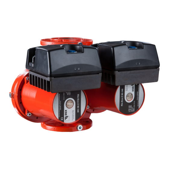
- Page 1 High-efficiency Circulator / Drinking Water Pump Rio-Eco N / Rio-Eco Z N / Rio- Eco Therm N Rio-Eco N 25-100, 30-100 to 80-120 Rio-Eco Z N Rio-Eco Therm N 30-100 to 65-120 Installation/Operating Manual...
- Page 2 All rights reserved. The contents provided herein must neither be distributed, copied, reproduced, edited or processed for any other purpose, nor otherwise transmitted, published or made available to a third party without the manufacturer's express written consent. Subject to technical modification without prior notice. © KSB Aktiengesellschaft, Frankenthal 22.08.2016...
-
Page 3: Table Of Contents
Contents Contents Glossary ............................5 General ............................6 Principles .................................6 Target group ..............................6 Symbols ................................6 Safety ............................. 7 Key to safety symbols/markings ........................7 General ................................7 Intended use ..............................7 Personnel qualification and training ......................8 Consequences and risks caused by non-compliance with this manual ............8 Safety awareness ............................8 Safety information for the operator/user .....................8 Safety information for maintenance, inspection and installation ..............9... - Page 4 Contents Commissioning/start-up ..........................20 Shutdown ..............................27 Operating limits ............................28 Shutdown/storage/preservation ........................28 Returning to service .............................29 Servicing/Maintenance ....................... 30 Servicing/inspection ............................30 Drainage/cleaning ............................30 Removing the pump set from the piping ....................30 Trouble-shooting ........................32 Related Documents ........................33 Sectional drawing with list of components ....................33 Electrical connection, overview of settings, LED displays ................33 EU Declaration of Conformity ....................
-
Page 5: Glossary
Glossary Glossary Discharge line Pump set The pipeline which is connected to the Complete pump set consisting of pump, drive, discharge nozzle additional components and accessories Noise characteristics Suction lift line/suction head line The noise emission to be expected, indicated as The pipeline which is connected to the suction sound pressure level LpA in dB(A) nozzle... -
Page 6: General
The name plate indicates the type series/size and main operating data. They uniquely identify the pump (set) and serve as identification for all further business processes. In the event of damage, immediately contact your nearest KSB service centre to maintain the right to claim under warranty. -
Page 7: Safety
2 Safety 2 Safety All the information contained in this section refers to hazardous situations. DANGER 2.1 Key to safety symbols/markings Table 2: Definition of safety symbols/markings Symbol Description DANGER DANGER This signal word indicates a high-risk hazard which, if not avoided, will result in death or serious injury. -
Page 8: Personnel Qualification And Training
2 Safety ▪ Observe the maximum flow rates indicated in the data sheet or product literature (to prevent overheating, mechanical seal damage, cavitation damage, bearing damage, etc). ▪ Do not throttle the flow rate on the suction side of the pump (to prevent cavitation damage). -
Page 9: Safety Information For Maintenance, Inspection And Installation
2 Safety ▪ If shutting down the pump does not increase potential risk, fit an emergency- stop control device in the immediate vicinity of the pump (set) during pump set installation. 2.8 Safety information for maintenance, inspection and installation ▪ Modifications or alterations of the pump are only permitted with the manufacturer's prior consent. -
Page 10: Transport/Temporary Storage/Disposal
On transfer of goods, check each packaging unit for damage. In the event of in-transit damage, assess the exact damage, document it and notify KSB or the supplying dealer (as applicable) and the insurer about the damage in writing immediately. -
Page 11: Disposal
3 Transport/Temporary Storage/Disposal 3.5 Disposal WARNING Fluids, consumables and supplies which are hot and/or pose a health hazard Hazard to persons and the environment! ▷ Collect and properly dispose of flushing fluid and any residues of the fluid handled. ▷ Wear safety clothing and a protective mask, if required. ▷... -
Page 12: Description Of The Pump (Set)
40 to 80 = DN 40 to DN 80 Head in m x 10 (example: 120 = 12 m) -130 Height 130 mm 4.3 Name plate Rio-Eco N 40-120 29134165 Made in EU KSB Aktiengesellschaft Johann-Klein-Straße 9 230V 67227 Frankenthal 50Hz Max 2,70A EEI ≤ 0,27 Class F PN6/10 / IP 42 / TF110 Fig. -
Page 13: Design Details
4 Description of the Pump (Set) 4.4 Design details Design ▪ Highly efficient, maintenance-free wet rotor pump (glandless) Drive ▪ Electronically commutated synchronous motor with permanent magnet rotor ▪ 230 V - 50 Hz ▪ IP42 enclosure ▪ Thermal class F ▪... -
Page 14: Configuration And Function
4 Description of the Pump (Set) 4.5 Configuration and function Fig. 2: Sectional drawing of the pump Discharge nozzle Plain bearing Motor Impeller Suction nozzle Motor shaft Design The pump is designed with a radial fluid inlet and a radial outlet arranged on the same axis. -
Page 15: Dimensions And Weight
4 Description of the Pump (Set) 4.8 Dimensions and weight For dimensions and weights please refer to the type series booklet of the pump. Rio-Eco N / Rio-Eco Z N / Rio-Eco Therm N 15 of 36... -
Page 16: Installation At Site
5 Installation at Site 5 Installation at Site 5.1 Safety regulations DANGER Installation in potentially explosive atmospheres Explosion hazard! ▷ Never install the pump in potentially explosive atmospheres. ▷ Observe the information given in the data sheet and on the name plates of the pump system. - Page 17 5 Installation at Site Table 6: Permissible installation positions Sizes Rio-Eco (Therm) N 30-100, 30-120 32-120, 40-100, 40-120, 50-70, 50-90 Rio-Eco (Therm) N 40-140, 50-140, 65-90, 65-120, 80-120 Rio-Eco Z N To do so, undo the bolts/screws and turn the motor head until it has reached its correct position.
-
Page 18: Connecting The Piping
5 Installation at Site Accurately insert the sealing element. Connect the pump flange to the pipe flange by means of screws. Tighten the screws hand-tight with an assembly tool (e.g. wrench). Accurately insert the sealing element on the opposite side. Connect the pump flange to the pipe flange by means of screws. -
Page 19: Electrical Connection
5 Installation at Site CAUTION Heat building up at motor housing and pump casing Pump overheating! ▷ Never insulate the motor and electronic system housings. 5.6 Electrical connection DANGER Electrical connection work by unqualified personnel Danger of death from electric shock! ▷... -
Page 20: Commissioning/Start-Up/Shutdown
6 Commissioning/Start-up/Shutdown 6 Commissioning/Start-up/Shutdown 6.1 Commissioning/start-up 6.1.1 Prerequisites for commissioning/start-up Before commissioning/starting up the pump set, make sure that the following conditions are met: ▪ The pump set has been properly connected to the power supply and is equipped with all protection devices. ▪... - Page 21 6 Commissioning/Start-up/Shutdown CAUTION Abnormal noises, vibrations, temperatures or leakage Damage to the pump! ▷ Switch off the pump (set) immediately. ▷ Eliminate the causes before returning the pump set to service. ✓ The system piping has been cleaned. ✓ Pump, suction line and inlet tank, if any, have been vented and primed with the fluid to be pumped.
- Page 22 6 Commissioning/Start-up/Shutdown 6.1.4 Mode of operation 6.1.4.1 Automatic control The closed-loop control mode integrated in the pump is active when the operating Internal . The operating mode can be set at DIP switch 1. mode is set to DIP switch 1 = ON Operating mode External Internal...
- Page 23 6 Commissioning/Start-up/Shutdown 6.1.4.2 Open-loop control: The closed-loop control mode integrated in the pump is active when the operating Internal . The operating mode can be set at DIP switch 1. mode is set to External DIP switch 1 = ON Operating mode DIP switch 1 = OFF Operating mode...
- Page 24 6 Commissioning/Start-up/Shutdown The pump is operated in open-loop control mode depending on the external analog speed signal (0-10 VDC) (setpoint) (0 VDC = minimum speed / 10 VDC = maximum speed). n [min U [V] 10 V Fig. 9: Interdependence between the speed setpoint and the external input signal 6.1.4.4 Operation via Modbus The pumps Rio-Eco N 25-100, 30-100 to 80-120 come with a Modbus interface...
- Page 25 6 Commissioning/Start-up/Shutdown 6.1.4.6 Operating mode twin pump DIP switch 2 = ON Twin pump DIP switch 2 = OFF Single pump Fig. 11: DIP switch (example: twin pump operating mode and control integrated in the pump) The control modules of both pumps are connected with the data cable which is contained in the scope of supply of the Rio-Eco Z N pump (also see accessories).
- Page 26 6 Commissioning/Start-up/Shutdown Two individual pumps of the same performance data can be controlled and operated individually by an automation system via Modbus. In this case, the automation system will control the operating mode and the operating status of each pump separately. The two pumps must be connected to the automation system with the Modbus connection cable, which is available as an option (see accessories).
-
Page 27: Shutdown
6 Commissioning/Start-up/Shutdown Table 9: Display of error codes Flashing frequency Cause of failure 1 - pause - 1 Excessive electronics temperature 2 - pause - 2 Excessive motor temperature 3 - pause - 3 Motor is overloaded 4 - pause - 4 Pump is overloaded 5 - pause - 5 Internal control error... -
Page 28: Operating Limits
6 Commissioning/Start-up/Shutdown 6.3 Operating limits DANGER Non-compliance with operating limits for pressure, temperature, fluid handled and speed Hot fluid may escape! ▷ Comply with the operating data indicated in the data sheet. ▷ Avoid prolonged operation against a closed shut-off element. ▷... -
Page 29: Returning To Service
6 Commissioning/Start-up/Shutdown 6.5 Returning to service For returning the pump to service observe the sections on commissioning/start-up and the operating limits. In addition, carry out all servicing/maintenance operations before returning the pump (set) to service. WARNING Failure to re-install or re-activate protective devices Risk of injuries by escaping fluid! ▷... -
Page 30: Servicing/Maintenance
7 Servicing/Maintenance 7 Servicing/Maintenance 7.1 Servicing/inspection The circulator pumps are almost maintenance-free. If the pump has not been in operation for a prolonged period of time or if the system is severely contaminated, the rotor can become blocked. The rotor can be deblocked by undoing the screwed plug, inserting a screw driver into the shaft end, and rotating the rotor. - Page 31 7 Servicing/Maintenance WARNING Danger by strong magnetic field Danger of crushing injuries when pulling out the rotor! Due to the strong magnetic field the rotor can be suddenly pulled back into its original position! Danger of magnetic parts near the rotor being attracted! ▷...
-
Page 32: Trouble-Shooting
If problems occur that are not described in the following table, consultation with the KSB customer service is required. Pump not running — no LED display Pump starts up but stops again immediately Pump not running —... -
Page 33: Related Documents
9 Related Documents 9 Related Documents 9.1 Sectional drawing with list of components 81-59 818 814 81-22 Part No. Description Part No. Description Volute casing Impeller Plain bearing 81-22 Terminal box cover 81-59 Stator Copper windings Rotor 9.2 Electrical connection, overview of settings, LED displays Power Fig. -
Page 34: Eu Declaration Of Conformity
10 EU Declaration of Conformity 10 EU Declaration of Conformity Manufacturer: KSB Aktiengesellschaft Johann-Klein-Straße 9 67227 Frankenthal (Germany) The manufacturer herewith declares that the product: Rio-Eco N, Rio-Eco Z N, Rio-Eco Therm N Series code range: 1616 to 1752 ▪ is in conformity with the provisions of the following Directives as amended from time to time: –... -
Page 35: Index
Index Index Applications 7 Manual functions 13 Automatic functions 13 Misuse 8 Bearings 13 Name plate 12 Commissioning 20 Operating limits 28 Connections 13 Operating modes 13 Design 13 Piping 18 Designation 12 Preservation 10, 28 Disposal 11 Product description 12 Drive 13 Return to supplier 10 External control functions 13... - Page 36 KSB Aktiengesellschaft 67225 Frankenthal • Johann-Klein-Str. 9 • 67227 Frankenthal (Germany) Tel. +49 6233 86-0 • Fax +49 6233 86-3401 www.ksb.com...
Need help?
Do you have a question about the Rio-Eco N Series and is the answer not in the manual?
Questions and answers