KSB Amarex KRT Installation & Operating Manual
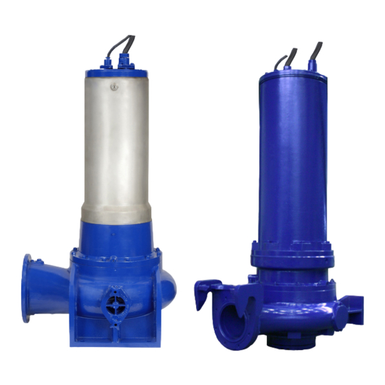
Submersible motor pump
Hide thumbs
Also See for Amarex KRT:
- Installation & operating manual (124 pages) ,
- Operating and maintenance instructions manual (96 pages) ,
- Supplementary operating manual (46 pages)
Table of Contents

Related Manuals for KSB Amarex KRT


Summary of Contents for KSB Amarex KRT
- Page 1 Submersible Motor Pump Amarex KRT Sizes DN 100 to DN 700; 60 Hz 4-pole: 35 4_N to 350 4_N 6-pole: 32 6_N to 480 6_N 8-pole: 26 8_N to 400 8_N 10-pole: 40 10 _N to 350 10_N 12-pole: 195 12_N to 300 12_N Installation/Operating Manual Mat.
- Page 2 All rights reserved. The contents provided herein must neither be distributed, copied, reproduced, edited or processed for any other purpose, nor otherwise transmitted, published or made available to a third party without the manufacturer's express written consent. Subject to technical modification without prior notice. © KSB SE & Co. KGaA, Frankenthal 1/31/2018...
-
Page 3: Table Of Contents
Installing the pump set .......................... 29 5.3.1 Stationary wet installation ........................ 29 5.3.2 Stationary dry installation ......................... 41 5.3.3 Wet installation of a transportable model.................. 45 Electrical system.............................. 46 5.4.1 Information for planning the control system .................. 46 5.4.2 Electrical connection.......................... 51 Commissioning/Start-up/Shutdown.................... 54 Commissioning/start-up .......................... 54 Amarex KRT 3 of 128... - Page 4 9.2.10 Connection space of K35 motors .................... 108 9.2.11 Bail .............................. 108 Wiring diagrams ............................ 109 9.3.1 Wiring diagram for the power cables .................... 109 9.3.2 Wiring diagrams for the sensors ..................... 110 Flamepaths on explosion-proof motors ...................... 118 Sectional drawings of the mechanical seal .................... 119 Amarex KRT 4 of 128...
- Page 5 Contents Certificate of Decontamination...................... 122 Index .............................. 123 Amarex KRT 5 of 128...
-
Page 6: Glossary
The part of the pump in which the kinetic energy is converted into pressure energy Pump set Complete pump set consisting of pump, drive, additional components and accessories Suction lift line/suction head line The pipeline which is connected to the suction nozzle Amarex KRT 6 of 128... -
Page 7: General
200-501 200-502 200-503 200-631 250-400 250-401 250-403 250-632 250-900 300-400 300-401 300-403 300-420 300-500 300-503 300-505 350-420 350-500 350-501 350-503 350-632 350-633 350-636 350-710 350-713 400-500 400-632 400-900 Not for pump sets with cooling system Amarex KRT 7 of 128... -
Page 8: Installation Of Partly Completed Machinery
In the event of damage, immediately contact your nearest KSB Service center to maintain the right to claim under warranty. 1.2 Installation of partly completed machinery To install partly completed machinery supplied by KSB refer to the sub-sections under Servicing/Maintenance. -
Page 9: Symbols
Conditions which need to be fulfilled before proceeding with the ✓ step-by-step instructions ⊳ Safety instructions ⇨ Result of an action ⇨ Cross-references Step-by-step instructions Note Recommendations and important information on how to handle the product Amarex KRT 9 of 128... -
Page 10: Safety
▪ Do not operate partially assembled pump sets. ▪ Only use the pump set to handle the fluids described in the data sheet or product literature of the pump variant. ▪ Never operate the pump set without the fluid to be handled. Amarex KRT 10 of 128... -
Page 11: Personnel Qualification And Personnel Training
2.5 Consequences and risks caused by non-compliance with these operating instructions ▪ Non-compliance with these operating instructions will lead to forfeiture of warranty cover and of any and all rights to claims for damages. ▪ Non-compliance can, for example, have the following consequences: Amarex KRT 11 of 128... -
Page 12: Safety Awareness
Before returning the product to service, observe all instructions on commissioning. (ð Section 6.1, Page 54) 2.9 Unauthorized modes of operation Never operate the pump (set) outside the limits stated in the data sheet and in this manual. Amarex KRT 12 of 128... -
Page 13: Explosion Protection
▪ Modifications or alteration of the pump set could affect explosion protection and are only permitted after consultation with the manufacturer. ▪ Only original spare parts and accessories authorized by the manufacturer must be used for explosion-proof pumps. Amarex KRT 13 of 128... -
Page 14: Transport/Temporary Storage/Disposal
1. On transfer of goods, check each packaging unit for damage. 2. In the event of in-transit damage, assess the exact damage, document it and notify KSB or the distributor and the insurance company about the damage in writing immediately. -
Page 15: Setting The Pump Set Down In A Horizontal Position
Damage to the cooling system! ▷ Never place the pump set on the cooling jacket or fasten it by the cooling system. Pump sets equipped with a cooling system are delivered with a support foot as a transport lock. Amarex KRT 15 of 128... -
Page 16: Placing The Pump Set In A Vertical Position
Improper storage Damage to the power cables! ▷ Support the power cables at the cable entry to prevent permanent deformation. ▷ Only remove the protective caps from the power cables at the time of installation. Amarex KRT 16 of 128... -
Page 17: Return To Supplier
4. Always complete and enclose a certificate of decontamination when returning the pump. Always indicate any safety measures and decontamination measures taken. (ð Section 10, Page 122) NOTE If required, a blank certificate of decontamination can be downloaded from the KSB web site at: www.ksb.com/certificate_of_decontamination Amarex KRT 17 of 128... -
Page 18: Disposal
2. Separate and sort the pump materials, e.g. by: - Metals - Plastics - Electronic waste - Greases and other lubricants 3. Dispose of materials in accordance with local regulations or in another controlled manner. Amarex KRT 18 of 128... -
Page 19: Description Of The Pump (Set)
Pump for handling untreated waste water containing long fibers and solid substances, liquids containing air/gas, and raw sludge, activated sludge and digested sludge. 4.2 Designation Example: Amarex KRT K 150-403/80 4 UN G-S IE3 Table 6: Designation key Code Description Amarex KRT... -
Page 20: Name Plate
Motor efficiency classification to IEC 60034-30 No efficiency classification High Efficiency (IE = International Efficiency) Premium Efficiency (IE = International Efficiency) 4.3 Name plate KSB SE & Co. KGaA KSB SE & Co. KGaA Johann-Klein-Straße 9 Johann-Klein-Straße 9 67227 Frankenthal... -
Page 21: Types Of Installation
Operation with the motor outside the fluid handled is possible for short periods. Pump sets of installation types D and K are suitable for continuous operation with the motor outside the fluid. The motor is cooled by the integrated cooling system. Amarex KRT 21 of 128... -
Page 22: Configuration And Function
The heat generated by the motor is transferred via the discharge cover to the fluid handled by internal circulation. The coolant serves as anti-corrosive and antifreeze agent, and as a lubricant for the mechanical seals. Amarex KRT 22 of 128... -
Page 23: Noise Characteristics (Only For Dry Installation - Installation Type D)
▪ Foot plate or pump stool with mounting elements ▪ Lifting rope, lifting chain or lifting bail (optional) A separate name plate is included in KSB's scope of supply. Attach this name plate in a clearly visible position outside the place of installation, e.g. at the control panel, pipeline or mounting bracket. -
Page 24: Dimensions And Weights
4 Description of the Pump (Set) 4.9 Dimensions and weights For dimensions and weights refer to the general arrangement drawing/outline drawing or data sheet of the pump set. Amarex KRT 24 of 128... -
Page 25: Installation At Site
Impermissible solid objects (tools, screws/bolts or similar) in the pump sump/inlet tank during pump start-up Personal injury and damage to property! ▷ Check the pump sump/inlet tank for impermissible solid objects before flooding, and remove, if necessary. Amarex KRT 25 of 128... -
Page 26: Checks To Be Carried Out Prior To Installation
UG1051118 Fig. 5: Transport lock Support foot Remove the support foot (1) prior to commissioning and keep it for future servicing, temporary storage or decommissioning of the pump. Amarex KRT 26 of 128... -
Page 27: Checking The Lubricant Level (Installation Types S And P)
Always apply a liquid sealing agent (e.g. Hylomar SQ32M) to sealing surfaces marked with this symbol. NOTE If more than 1.59 quart [1.5 l] of lubricant are required for topping up, this suggests a defect of the mechanical seals. Amarex KRT 27 of 128... -
Page 28: Checking The Coolant Level (Installation Types D And K)
Risk of injuries, damage to the pump! ▷ Never insert your hands or any other objects into the pump. ▷ Check that the inside of the pump is free from any foreign objects. ▷ Take suitable precautions (e.g. wear safety goggles). Amarex KRT 28 of 128... -
Page 29: Installing The Pump Set
Always refer to and comply with the general arrangement drawing/outline drawing when installing the pump set. 5.3.1 Stationary wet installation 5.3.1.1 Fastening the base elbow Depending on the pump size, the base elbow is either fastened with chemical anchors and/or foundation rails. Amarex KRT 29 of 128... - Page 30 2. Insert chemical anchors 904.38. 3. Use chemical anchors 904.38 to bolt base elbow 72-1 with foundation rails 89-8.38/.39 to the floor. 4. Set the foundation rails in concrete. Chemical anchor dimensions Fig. 11: Dimensions Amarex KRT 30 of 128...
- Page 31 When the pump set is used for draining low-level building areas, fit a swing check valve into the discharge line to avoid backflow from the sewer system. SW = Width across flats Mounting accessories of the respective manufacturer are required. Amarex KRT 31 of 128...
- Page 32 The pump set is guided into the sump or tank along two parallel, tightly stretched guide cables made of stainless steel. It attaches itself automatically to the base elbow which has been fitted to the floor. Amarex KRT 32 of 128...
- Page 33 Fig. 13: Mounting bracket variant for sizes 200-402, 200-403 and sizes with nominal discharge nozzle diameters DN 100 and DN 150 Table 14: List of components Part No. Description Part No. Description 59-18 Hook Guide cable suspension bracket 59-24.01 Guide cable Mounting bracket 90-3.37 Anchor bolt Grub screw Bail 920.36/.37 Amarex KRT 33 of 128...
- Page 34 DN 350, DN 400, DN 500, DN 600 and DN 700 Table 16: List of components Part No. Description Part No. Description 59-18 Hook Guide cable suspension bracket 59-24.01 Guide cable 901.36 Hexagon head bolt 550.36 Disc Grub screw Thrust insert 920.36 Amarex KRT 34 of 128...
- Page 35 10,3 1349 6000 200-501 22,1 2248 10000 200-502 22,1 2248 10000 200-503 22,1 2248 10000 200-631 22,1 2248 10000 250-400 22,1 2248 10000 250-401 22,1 2248 10000 250-403 22,1 2248 10000 250-632 22,1 2248 10000 Amarex KRT 35 of 128...
- Page 36 NOTE The guide rails are not included in KSB's scope of supply. Select guide rail materials which are suitable for the fluid handled or as specified by the operator.
- Page 37 5. Tighten nuts 920.37. This pulls clamping sleeves 81-51.37 upwards and expands sleeves 520.37 against the inside pipe diameter. 6. Lock nuts 920.37 with a second nut each and secure them with Loctite 243. Amarex KRT 37 of 128...
- Page 38 1. Fasten claw 732 to the discharge flange with studs 902.35, discs 550.35 and nuts 920.35. Observe the tightening torques. 2. Fit profile joint 410 or round cord 99-6 into the groove of the claw. This will seal the base elbow/pump connection. Attaching the lifting chain/rope Stationary wet installation Amarex KRT 38 of 128...
- Page 39 Attach the lifting chain or rope to the eyebolt opposite the discharge nozzle or to the bail of the pump set. This attachment point achieves a forward inclination of the pump set towards the discharge nozzle, which allows the pump claw to hook onto the base elbow. Amarex KRT 39 of 128...
- Page 40 1. Guide the pump set over the suspension bracket/mounting bracket, thread it onto the guide cables/rails and slowly lower it down. The pump set attaches itself to base elbow 72-1. 2. Attach the lifting chain/rope to hook 59-18 at the mounting bracket. Amarex KRT 40 of 128...
-
Page 41: Stationary Dry Installation
5.3.2 Stationary dry installation 5.3.2.1 Installing the pump set NOTE If foundation rails 89-8 are included in KSB's scope of supply, they must be set in concrete as shown in the general arrangement drawing/outline drawing. 5.3.2.1.1 Installing the pump set with a soleplate Only for sizes 200-330, 200-402, 200-403, 200-501, 200-502, 200-503 and sizes with nominal discharge nozzle diameters DN 100 and DN 150... - Page 42 Incorrect grounding during welding work on the piping Destruction of rolling element bearings (pitting effect)! ▷ Never ground the electric welding equipment on the pump or baseplate. ▷ Prevent current flowing through the rolling element bearings. Amarex KRT 42 of 128...
- Page 43 5620 41900 18735 22994 14752 32971 Table 22: Forces and moments based on DIN EN ISO 5199 Forces [N] Moments [Nm] ΣF ΣM 3000 2700 3350 5250 1750 1250 1450 2600 4200 3750 3400 6600 1750 2100 1500 3150 Amarex KRT 43 of 128...
- Page 44 G 1 1/2 Casing drain G 1 5.3.2.2.3 Vacuum balance line NOTE Where fluid has to be pumped out of a vessel under vacuum, installing a vacuum balance line is recommended. For sizes K500-630: G1 1/2; K600-520: G 2 Amarex KRT 44 of 128...
-
Page 45: Wet Installation Of A Transportable Model
Tighten the screws/bolts as specified in the “Tightening torques” table. Attaching the lifting chain/rope Fig. 30: Attaching the lifting chain/rope 1. Attach the lifting chain or rope to the lug/eyebolt on the discharge nozzle side (see illustration on the left and table "Types of attachment"). Amarex KRT 45 of 128... -
Page 46: Electrical System
5.4.1.3 Frequency inverter operation The pump set is suitable for operation on a frequency inverter as per IEC 60034-17. DANGER Operation outside the permitted frequency range Explosion hazard! ▷ Never operate an explosion-proof pump set outside the specified range. Amarex KRT 46 of 128... - Page 47 No modifications are required on the power/control cable of the submersible motor pump. Suitable analyzing devices must be selected. To monitor the leakage sensor inside the motor using a special relay available from KSB is recommended. 5.4.1.4 Sensors DANGER...
- Page 48 ▷ Never use the resistance thermometers as a sole means of monitoring the motor temperature. 5.4.1.4.2 Leakage inside the motor DANGER Incorrect monitoring of leakage electrode Explosion hazard! Danger of death from electric shock! ▷ Voltages must be < 30 V AC and tripping currents < 0.5 mA. Amarex KRT 48 of 128...
- Page 49 This sensor is a Pt100 resistance thermometer (core identification 15 and 16). Connect the sensor to a temperature control device with a Pt100 input and 2 separate outputs for two different switching points (sensor circuit maximum 6 V/2 mA). Amarex KRT 49 of 128...
- Page 50 5.4.1.4.5 Vibrations As an option, the pump set can be supplied with a vibration sensor in the area of the upper bearing. The sensor is matched to KSB's diagnosis systems. The vibration sensor measures the root-mean-square value of the radial vibration velocity at the upper bearing.
-
Page 51: Electrical Connection
DANGER Operating an incompletely connected pump set Explosion hazard! Damage to the pump set! ▷ Never start up a pump set with an incompletely connected power cable or non- operational monitoring devices. Amarex KRT 51 of 128... - Page 52 Pump sets for dry installation are provided with an external potential equalization type D) connection. Potential equalization shall be provided for in compliance with IEC 60204. DANGER Incorrect connection Danger of death from electric shock! ▷ Never operate the pump set without connecting the PE conductor. Amarex KRT 52 of 128...
- Page 53 Fig. 33: Connecting the potential equalization conductor Potential equalization conductor 1. Connect the potential equalization conductor to terminal 81-51 provided on the outside of bearing housing 350. 2. Fasten the conductor with hexagon head bolts 901.30 and spring washers 932.30. Amarex KRT 53 of 128...
-
Page 54: Commissioning/Start-Up/Shutdown
1. Vent the pump and suction line and prime both with the fluid to be handled. 2. Fully open the shut-off element in the suction line. 3. Fully open all auxiliary connections (barrier fluid, flushing liquid, etc). Amarex KRT 54 of 128... -
Page 55: Start-Up
▷ Never operate the pump set without liquid fill. ▷ Prime the pump as per operating instructions. ▷ Always operate the pump within the permissible operating range. WARNING Hot surface Risk of burns ▷ Never touch a pump set which is in operation. Amarex KRT 55 of 128... -
Page 56: Shutdown (Dry Installation Only - Installation Type D)
For prolonged shutdown periods: 1. Close the shut-off element in the suction line. 2. Close any auxiliary lines. CAUTION Danger of freezing! Damage to the pump set! ▷ Drain the pump set or protect it against freezing. Amarex KRT 56 of 128... -
Page 57: Operating Limits
The voltage difference between the individual phases must not exceed 1 %. 6.2.3 Frequency inverter operation DANGER Operation outside the permitted frequency range Explosion hazard! ▷ Never operate an explosion-proof pump set outside the specified range. Amarex KRT 57 of 128... -
Page 58: Fluid Handled
Fig. 34: Minimum level of fluid handled Pump sets without cooling system (installation types P and S) Pump sets without cooling system are designed for continuously submerged operation. This condition has to be fulfilled for the motor to be cooled sufficiently. Amarex KRT 58 of 128... -
Page 59: Shutdown/Storage/Preservation
Risk of injury by moving components and shock currents! ▷ Make sure that the pump set cannot be started up unintentionally. ▷ Always make sure the electrical connections are disconnected before carrying out work on the pump set. Amarex KRT 59 of 128... -
Page 60: Returning To Service
Risk of personal injury from moving parts or escaping fluid! ▷ As soon as the work is completed, re-install and/or re-activate any safety- relevant devices and protective devices. NOTE On pumps/pump sets older than 5 years we recommend replacing all elastomer seals. Amarex KRT 60 of 128... -
Page 61: Servicing/Maintenance
Risk of personal injury! ▷ Observe all relevant laws. ▷ When draining the fluid take appropriate measures to protect persons and the environment. ▷ Decontaminate pumps which handle fluids posing a health hazard. Amarex KRT 61 of 128... -
Page 62: Servicing/Inspection
(set) with a minimum of maintenance expenditure and work. NOTE All maintenance work, service work and installation work can be carried out by KSB Service or authorized workshops. Find your contact in the attached "Addresses" booklet or on the Internet at "www.ksb.com/contact". -
Page 63: Inspection Work
2. Measure the winding temperature sensor to chassis ground. To do so, connect all core ends of the winding temperature sensors together and connect all winding ends to chassis ground. At least every two years Amarex KRT 63 of 128... - Page 64 Lower resistance values would suggest water ingress into the motor. In this case the motor section must be opened and overhauled. Only for pump sets without cooling system, installation type S Optional Only for pump sets with vibration sensor Amarex KRT 64 of 128...
- Page 65 Risk of personal injury when opening the pump set! ▷ Be careful when opening the inner chambers. NOTE Slight wear of the mechanical seal is unavoidable. This will be aggravated by abrasive substances contained in the fluid handled. Optional Amarex KRT 65 of 128...
- Page 66 ▷ Never insert your hands or any other objects into the pump if the pump has not been de-energized and secured against unintentional start-up. If there is a problem which requires visual inspection, observe the following instructions: Amarex KRT 66 of 128...
-
Page 67: Coolant (Pump Sets With Cooling System Only - Installation Types D And K)
-4 °F [-20°C]. The coolant also lubricates the mechanical seals. 7.2.2.1 Coolant quality CAUTION Incorrect coolant mixture Corrosion of the cooling system ▷ Always use the exact coolant mixture. Amarex KRT 67 of 128... - Page 68 300-503 42,3 44,4 79,3 84,5 300-505 42,3 44,4 79,3 84,5 350-420 42,3 44,4 79,3 84,5 350-500 42,3 44,4 79,3 84,5 350-501 42,3 44,4 79,3 84,5 350-503 42,3 44,4 79,3 84,5 Manufacturer: Metalsol Chemie, Magdeburg, Germany Amarex KRT 68 of 128...
- Page 69 Cooling liquid spurting out due to excess pressure in the cooling liquid chamber at operating temperature! Risk of injuries by parts flying off and escaping cooling liquid! ▷ Open the screw plug of the cooling liquid chamber very carefully. Amarex KRT 69 of 128...
- Page 70 However, if the coolant is severely contaminated by the fluid handled, this suggests a defect at the mechanical seals. Amarex KRT 70 of 128...
-
Page 71: Lubrication And Lubricant Change
▪ Merkur WOP 40 PB, made by SASOL ▪ Merkur white oil Pharma 40, made by DEA ▪ Thin-bodied paraffin oil No. 7174, made by Merck ▪ Equivalent brands of medical quality, non-toxic ▪ Water-glycol mixture Amarex KRT 71 of 128... - Page 72 E, K 200-402 200-403 200-501 200-502 200-503 200-631 11,1 10,5 11,1 10,5 250-400 250-401 250-403 250-632 11,1 10,5 11,1 10,5 250-900 11,1 10,5 11,1 10,5 300-400 300-401 300-403 300-420 300-500 300-503 300-505 350-420 350-500 350-501 Amarex KRT 72 of 128...
- Page 73 ▷ Observe all legal regulations on the disposal of fluids posing a health hazard. WARNING Excess pressure in the lubricant chamber Liquid spurting out when the lubricant chamber is opened at operating temperature! ▷ Open the screw plug of the lubricant chamber very carefully. Amarex KRT 73 of 128...
- Page 74 Mix of different grease types Damage to the pump set! ▷ Make sure to use the right type of grease. ▷ Never mix different types of grease. The following greases can be used to lubricate the rolling element bearings: Amarex KRT 74 of 128...
- Page 75 Lubricating nipple An encapsulated water-tight lubricating nipple allows re-lubrication of the angular contact ball bearings without opening the pump. DANGER Dry running Explosion hazard! ▷ Re-lubricate explosion-proof pump sets outside potentially explosive atmospheres. Also see the section on grease quality. Amarex KRT 75 of 128...
- Page 76 4. Fill in grease via lubricating nipple 636.02. 5. Disconnect the pump set from the power supply again and make sure it cannot be started unintentionally. 6. Close screw plug 903.46 with joint ring 411.46 again. Amarex KRT 76 of 128...
-
Page 77: Drainage/Cleaning
▷ Close the shut-off elements in the suction line and discharge line. ▷ Drain the pump and release the pump pressure. ▷ Shut off any auxiliary feed lines. ▷ Allow the pump set to cool down to ambient temperature. Amarex KRT 77 of 128... -
Page 78: Preparing The Pump Set
50 8 50 8 60 10 110 10 300 12 75 10 150 10 90 10 190 10 105 12 135 12 165 12 100-400 K M20 100-401 100-401 K M20 150-400 K M20 M85 × 2 150-401 Amarex KRT 78 of 128... - Page 79 M85 × 2 M85 × 2 M85 × 2 M100 × 2 350-632 M125 × 2 M125 × 2 M125 × 2 M125 × 2 350-633 M125 × 2 M125 × 2 M125 × 2 M125 × 2 350-636 M125 × 2 M125 × 2 M125 × 2 M125 × 2 350-710 350-713 M125 × 2 M125 × 2 M125 × 2 M125 × 2 400-500 M100 × 2 M100 × 2 M100 × 2 M100 × 2 For impeller diameter 373 mm M75 × 2 Amarex KRT 79 of 128...
- Page 80 Pull off the impeller using a special impeller removal tool or forcing screw. NOTE The special impeller removal tool and forcing screw are not included in the scope of supply. They can be ordered separately from KSB. Amarex KRT 80 of 128...
- Page 81 K M24 ADS5 250-401 K M24 ADS5 250-403 K M24 ADS5 250-632 250-900 300-400 K M24 ADS5 300-401 K M24 ADS5 300-403 K M24 ADS5 ADS6 300-420 300-500 300-505 350-420 350-500 350-501 350-503 350-632 350-633 Amarex KRT 81 of 128...
- Page 82 1. Undo and remove hexagon socket head cap screw 914.10. ð The impeller/shaft connection is a tapered fit. 2. Remove impeller hub cap 260.01 or disc 550.23. ð For dismantling of the impeller, a jacking thread is provided at the impeller hub. Amarex KRT 82 of 128...
- Page 83 2. Remove O-ring 412.06. 3. Bend open lock washer 931.02, undo hexagon head bolt 901.87 and remove them together with disc 550.87. 4. Pull off impeller 230 with a special impeller fitting and removal tool. Amarex KRT 83 of 128...
- Page 84 3. Pull off impeller 230 with a special impeller fitting and removal tool. Fig. 48: Special impeller fitting and removal tool 4. Screw hexagon head bolt 1 into the shaft end to prevent any damage to the shaft thread. 5. Screw part 2 into the impeller. Amarex KRT 84 of 128...
- Page 85 1. Pull the rotating assembly of mechanical seal 433.02 and spacer sleeve 525 off shaft 210. 2. Remove discharge cover 163 from bearing housing 350. 3. Press the stationary seat of mechanical seal 433.02 out of discharge cover 163. Amarex KRT 85 of 128...
-
Page 86: Dismantling The Motor Section
7.5 Reassembling the pump set 7.5.1 General information/Safety regulations WARNING Improper lifting/moving of heavy assemblies or components Personal injury and damage to property! ▷ Use suitable transport devices, lifting equipment and lifting tackle to move heavy assemblies or components. Amarex KRT 86 of 128... -
Page 87: Reassembling The Motor Section
Before reassembling the motor section, check that all joints relevant to explosion protection (flamepaths) are undamaged. Any components with damaged flamepaths must be replaced. Only use original spare parts made by KSB for explosion-proof pumps. Observe the flamepath positions specified in the Annex. -
Page 88: Reassembling The Pump Section
1. Slide impeller 230 onto the shaft end. 2. Apply Loctite 243 as thread-locking agent to the thread of the impeller screw. 3. Screw in impeller screw 914.10 and disc 550.23, if any. Tighten with a torque wrench. Observe the tightening torques. Amarex KRT 88 of 128... - Page 89 Fig. 53: Special impeller fitting and removal tool. 3. Screw part 2 of the special impeller fitting and removal tool into the shaft end of the pump set. 4. Screw part 1 to fully threaded stud part 2. Amarex KRT 89 of 128...
- Page 90 Fig. 56: Special impeller fitting and removal tool 3. Screw part 2 of the special impeller fitting and removal tool into the shaft end of the pump set. 4. Screw part 1 to fully threaded stud part 2. Amarex KRT 90 of 128...
- Page 91 ü The shaft, rolling element bearings, mechanical seal and impeller have been assembled properly. 1. Insert the complete back pull-out unit into the pump casing. 2. Evenly tighten screwed connection 920.01 between pump casing and bearing housing 350 or adapter 82-5, as applicable. Amarex KRT 91 of 128...
-
Page 92: Leak Testing
ð The pressure must not drop during the test period. ð If the pressure does drop, check the seals and screwed connections. 4. Repeat the leak test if required. 5. Remove the testing device. 6. After the leak test, top up coolant/lubricant. Amarex KRT 92 of 128... -
Page 93: Checking The Connection Of Motor/Power Supply
Check the power cables after reassembly. (ð Section 7.2.1, Page 63) 7.6 Tightening torques Table 40: Tightening torques Property class A4-50 A4-70 1.4462 Rp 0.2 N/mm² Thread [lbf ft] [Nm] [lbf ft] [Nm] [lbf ft] [Nm] [lbf ft] [Nm] [lbf ft] [Nm] 12,5 12,5 1000 1035 1400 Amarex KRT 93 of 128... -
Page 94: Spare Parts Stock
Rolling element bearing, pump end 50 % 99-9 Set of sealing elements for the motor 100 % 99-9 Set of sealing elements for the hydraulic system 100 % For two years of continuous operation or 17,800 operating hours Amarex KRT 94 of 128... -
Page 95: Trouble-Shooting
If problems occur that are not described in the following table, consultation with KSB’s customer service is required. A Pump is running but does not deliver B Pump delivers insufficient flow rate... - Page 96 ✘ - Mechanical seal monitor has tripped. Have cause determined and eliminated by qualified and trained personnel. - Bearing temperature monitor has tripped. Have cause determined and eliminated by ✘ qualified and trained personnel. Amarex KRT 96 of 128...
-
Page 97: Related Documents
932.01 421.01 80-1 421.03 500.05 914.02 412.03 412.02 412.46 512.02 421.02 932.02 550.03 433.01 23-2 932.03 914.08 914.23 412.04 412.15 433.02 550.87 525.04 903.01* 411.01 412.17* 503* 260.01 940.01 931.02 412.06 Fig. 62: General assembly drawing Amarex KRT 97 of 128... - Page 98 Table 43: Key to the symbols and codes Symbol Description Always secure screwed connections marked with this symbol with Loctite 243. Always apply a liquid sealing agent (e.g. Hylomar SQ32M) to sealing surfaces marked with this symbol. Amarex KRT 98 of 128...
- Page 99 Screw plug 410.03/.04 Profile seal 914.01/.02/.04/.05/.08/.23 Hexagon socket head cap screw 411.01/.02/.07/.22/.31/.33 Joint ring 920.01/.17 .34/.46 412.01/.02/.03/.04/.05/.06/.07/ O-ring 931.02 Lock washer .08/.15/.17/.45/.46 421.01/.02/.03 Lip seal 932.01/.02/.03/.13/.20/.37 Circlip 433.01/.02 Mechanical seal 940.01 500.04/.05 Ring 970.02 Label/plate Amarex KRT 99 of 128...
-
Page 100: Pump Sets Without Cooling System (Installation Types S And P)
69-6.01 520.01 932.13 931.01 421.01 80-1 421.03 500.05 914.02 412.03 412.02 512.02 421.02 550.03 932.03 902.01 932.02 920.01 433.01 412.04 412.15 412.24 433.02 525.04 412.17 550.87 901.87 260.01 940.01 931.02 412.06 Fig. 65: General assembly drawing Amarex KRT 100 of 128... - Page 101 Table 45: Key to the symbols and codes Symbol Description Always secure screwed connections marked with this symbol with Loctite 243. Always apply a liquid sealing agent (e.g. Hylomar SQ32M) to sealing surfaces marked with this symbol. Amarex KRT 101 of 128...
- Page 102 903.02/.03/.05/.31/.46 Screw plug 412.01/.02/.03/.04/.06/.07/.08/ O-ring 914.01/.02/.04/.05 Hexagon socket head cap .15/.17/.24 screw 421.01/.02/.03 Lip seal 920.01 433.01/.02 Mechanical seal 931.01/.02 Lock washer 500.04/.05 Ring 932.01/.02/.03/.13/.20/.37 Circlip Casing wear ring 940.01 Impeller wear ring 970.02 Label/plate Amarex KRT 102 of 128...
-
Page 103: Detailed Views
Terminal board 81-29.01/.02 Terminal 900.06/.26 Bolt/screw 81-45 Float switch 901.01 Hexagon head bolt 82-14.50 Cable with plug 903.34 Screw plug 82-5.50/.51 Adapter 914.19/.51 Hexagon socket head cap screw 99-17 Desiccant 920.23/.24 99-4.01/.02 Conversion kit 932.06/.19/.23/.26 Circlip Amarex KRT 103 of 128... -
Page 104: Sensors And Terminals - Pump Set Without Cooling System
81-2.01/.02/.03 Plug Terminal board 81-29.01/.02 Terminal 900.06/.26 Bolt/screw 81-45 Float switch 901.01 Hexagon head bolt 82-14.50 Cable with plug 914.19/.51 Hexagon socket head cap screw 82-5.50/.51 Adapter 920.23/.24 99-17 Desiccant 932.06/.19/.23/.26 Circlip 99-4.01/.02 Conversion kit Amarex KRT 104 of 128... -
Page 105: Bearings - Pump Set With Cooling System
Fig. 71: Bearings - pump set without cooling system Motors: 35 4...80 4, 32 6...60 6, 26 8...50 8 Motors: 35 4...110 4, 32 6...100 6, 26 8...75 8 *: Additional Table 52: List of components Part No. Description Part No. Description 500.01/.03 Ring Amarex KRT 105 of 128... -
Page 106: Bearing Housing Made Of Stainless Steel
Part No. Description Bearing bracket 932.37 Circlip Motors: 200 4...350 4 190 6...480 6 150 8...400 8 110 10...350 10 105 12...300 12 914.48 Fig. 74: Bearing bracket fastening Table 55: List of components Part No. Description Part No. Description Bearing bracket 914.48 Hexagon socket head cap screw Amarex KRT 106 of 128... -
Page 107: Special Feature Of Hydraulic System - Pump Set With Cooling System
920.27 412.04 412.24 412.40 Fig. 76: Special feature of hydraulic system - pump set without cooling system Table 57: List of components Part No. Description Part No. Description Discharge cover 902.27 Stud 412.04/.15/.24/.40 O-ring 920.27 Seal cover Amarex KRT 107 of 128... -
Page 108: Connection Space Of K35 Motors
Part No. Description Part No. Description 68-3.03 Cover plate 914.50 Hexagon socket head cap screw 9.2.11 Bail 902.13 920.13 Fig. 79: Bail Table 60: List of components Part No. Description Part No. Description Bail 920.13 902.13 Stud Amarex KRT 108 of 128... -
Page 109: Wiring Diagrams
9 Related Documents 9.3 Wiring diagrams 9.3.1 Wiring diagram for the power cables Fig. 80: Wiring diagram for the power cables * Shielded cable optional Up to 3 parallel cable pairs possible Amarex KRT 109 of 128... -
Page 110: Wiring Diagrams For The Sensors
Fig. 81: Sensor wiring diagram for standard pump sets, installation types D and K Shielded cables optional Motor temperature (PTC) Ⓐ Ⓑ Mechanical seal leakage Bearing temperature (lower bearings) Ⓒ Ⓓ Bearing temperature (upper bearing, optional) Leakage inside the motor Ⓕ Amarex KRT 110 of 128... - Page 111 Fig. 82: Sensor wiring diagram for pump sets with additional monitoring by vibration sensor, installation types D and K Ⓐ Motor temperature (PTC) Ⓑ Mechanical seal leakage Ⓒ Bearing temperature (lower bearings) Ⓓ Bearing temperature (upper bearing, optional) Ⓕ Leakage inside the motor Ⓖ Vibration sensor Amarex KRT 111 of 128...
- Page 112 Fig. 83: Sensor wiring diagram for pump sets with additional Pt100 motor temperature monitoring, installation types D and K Ⓐ Motor temperature (PTC) Mechanical seal leakage Ⓑ Ⓒ Bearing temperature (lower bearings) Bearing temperature (upper bearing, optional) Ⓓ Ⓕ Leakage inside the motor Ⓗ Motor temperature (Pt100) Amarex KRT 112 of 128...
- Page 113 Pt100 for the motor temperature and vibration sensor, installation types D and K Motor temperature (PTC) Ⓐ Ⓑ Mechanical seal leakage Bearing temperature (lower bearings) Ⓒ Ⓓ Bearing temperature (upper bearing, optional) Leakage inside the motor Ⓕ Ⓖ Vibration sensor Motor temperature (Pt100) Ⓗ Amarex KRT 113 of 128...
- Page 114 Fig. 85: Sensor wiring diagram for standard pump sets, installation types P and S Shielded cables optional Ⓐ Motor temperature (PTC) Ⓑ Mechanical seal leakage Ⓒ Bearing temperature (lower bearings) Ⓓ Bearing temperature (upper bearing, optional) Ⓔ Motor temperature Ⓕ Leakage inside the motor Amarex KRT 114 of 128...
- Page 115 P and S Ⓐ Motor temperature (PTC) Mechanical seal leakage Ⓑ Ⓒ Bearing temperature (lower bearings) Ⓓ Bearing temperature (upper bearing, optional) Ⓔ Motor temperature Ⓕ Leakage inside the motor Ⓖ Vibration sensor Amarex KRT 115 of 128...
- Page 116 P and S Ⓐ Motor temperature (PTC) Ⓑ Mechanical seal leakage Ⓒ Bearing temperature (lower bearings) Ⓓ Bearing temperature (upper bearing, optional) Ⓔ Motor temperature Ⓕ Leakage inside the motor Ⓗ Motor temperature (Pt100) Amarex KRT 116 of 128...
- Page 117 Pt100 for the motor temperature and vibration sensor, installation types P and S Motor temperature (PTC) Ⓐ Ⓑ Mechanical seal leakage Ⓒ Bearing temperature (lower bearings) Ⓓ Bearing temperature (upper bearing, optional) Ⓔ Motor temperature Ⓕ Leakage inside the motor Ⓖ Vibration sensor Ⓗ Motor temperature (Pt100) Amarex KRT 117 of 128...
-
Page 118: Flamepaths On Explosion-Proof Motors
9 Related Documents 9.4 Flamepaths on explosion-proof motors Fig. 89: Flamepaths on explosion-proof motors 1, 2, 3, 4, 5, 6, 7 Flamepaths Amarex KRT 118 of 128... -
Page 119: Sectional Drawings Of The Mechanical Seal
*: Only for pump sets with cooling system Table 62: List of components Part No. Description Part No. Description 23-2 Auxiliary impeller 550.03 Disc 412.17 O-ring Flange 433.01/.02 Mechanical seal 914.08 Hexagon socket head cap screw 525.04 Spacer sleeve 932.03 Circlip Locking sleeve Amarex KRT 119 of 128... - Page 120 Fig. 93: Mechanical seal depending on the motor *: Only for pump sets with cooling system Table 65: Key to the symbols and codes Symbol Description Always secure screwed connections marked with this symbol with Loctite 243. Amarex KRT 120 of 128...
- Page 121 9 Related Documents Table 66: List of components Part No. Description Part No. Description 23-2 Auxiliary impeller Locking sleeve 412.17 O-ring Flange 433.01/.02 Mechanical seal 904.01/.02 Grub screw 525.04 Spacer sleeve 914.08 Hexagon socket head cap screw Amarex KRT 121 of 128...
- Page 122 We confirm that the above data and information are correct and complete and that dispatch is effected in accordance with the relevant legal provisions....................................Place, date and signature Address Company stamp Required fields Amarex KRT 122 of 128...
- Page 123 Insulation resistance measurement 62 Shutdown 60 Intended use 10 Spare part Interference immunity 47 Ordering spare parts 94 Spare parts stock 94 Start-up 55, 56 Key to safety symbols/markings 10 Storage 16, 60 Supply voltage 57 Leakage monitoring 49 Level control 46 Tightening torques 93 Lubricant Transport 14 Intervals 63 Quantity 72 Amarex KRT 123 of 128...
- Page 124 Index Warnings 10 Amarex KRT 124 of 128...
- Page 128 KSB SE & Co. KGaA Johann-Klein-Straße 9 • 67227 Frankenthal (Germany) Tel. +49 6233 86-0 www.ksb.com...
Need help?
Do you have a question about the Amarex KRT and is the answer not in the manual?
Questions and answers