
Subscribe to Our Youtube Channel
Related Manuals for KSB Delta Macro F


Summary of Contents for KSB Delta Macro F
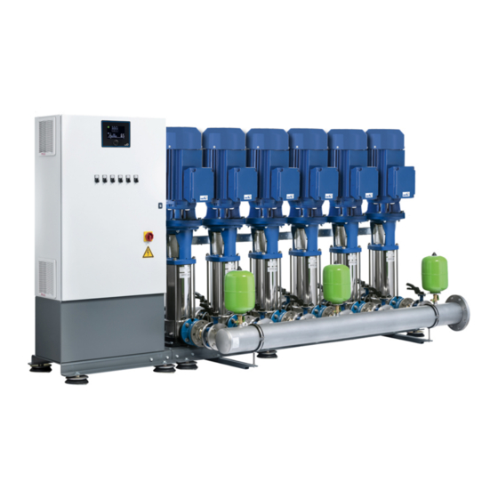
- Page 1 Pressure Booster System KSB Delta Macro KSB Delta Macro F KSB Delta Macro VC KSB Delta Macro SVP Installation/Operating Manual...
- Page 2 Subject to technical modification without prior notice. © KSB B.V., Alphen aan den Rijn, Nederland 10/11/2021...
-
Page 3: Table Of Contents
Installation at Site .......................... 27 Installation .............................. 27 Installing the pressure booster system ...................... 27 Mounting the accumulator.......................... 28 Connecting the piping ........................... 28 5.4.1 Fitting an expansion joint (optional).................... 29 5.4.2 Fitting the pressure reducer (optional) .................... 29 Electrical connection ............................ 30 KSB Delta Macro 3 of 92... - Page 4 Trouble-shooting: frequency inverter ...................... 51 Related Documents .......................... 53 10.1 General drawings with list of components.................... 53 10.1.1 KSB Delta Macro F/VC/SVP with Movitec 2B, 4B, 6B, 10B, 15C............ 53 10.1.2 KSB Delta Macro F/VC/SVP with Movitec 25B, 40B, 60B, 90B, 125B.......... 54 10.2 Parameter lists .............................. 55 10.2.1 Configuration............................. 55...
- Page 5 10.3 Messages ................................. 80 10.3.1 Messages for specific pumps ...................... 80 10.3.2 Messages for additional devices ....................... 82 10.3.3 Messages for specific functions...................... 83 EU Declaration of Conformity ...................... 86 Certificate of Decontamination...................... 87 Commissioning Report......................... 88 Index .............................. 89 KSB Delta Macro 5 of 92...
-
Page 6: Glossary
Premium Efficiency (IE = International Efficiency) Manual mode Direct operation on the power supply network, independently of the control unit. Switchgear and controlgear assembly Control cabinet with one or several control units / switchgears and electrical equipment. KSB Delta Macro 6 of 92... -
Page 7: General
The serial number uniquely describes the product and is used as identification in all further business processes. In the event of damage, immediately contact your nearest KSB service facility to maintain the right to claim under warranty. 1.2 Software changes The software has been specially created for this product and thoroughly tested. -
Page 8: Key To Safety Symbols/Markings
In conjunction with one of the signal words this symbol indicates a hazard involving electrical voltage and identifies information about protection against electrical voltage. Machine damage In conjunction with the signal word CAUTION this symbol indicates a hazard for the machine and its functions. KSB Delta Macro 8 of 92... -
Page 9: Safety
2.2.1 Prevention of foreseeable misuse ▪ Never exceed the permissible application and operating limits specified in the data sheet or product literature regarding temperature, etc. ▪ Observe all safety information and instructions in this manual. KSB Delta Macro 9 of 92... -
Page 10: Personnel Qualification And Personnel Training
▪ Carry out work on the pressure booster system during standstill only. ▪ The pump casing must have cooled down to ambient temperature. ▪ Pump pressure must have been released and the pump must have been drained. KSB Delta Macro 10 of 92... -
Page 11: Unauthorised Modes Of Operation
The following limit values and inspection/test levels must be complied with if the generic standard on interference emissions applies: An EMC plan must be devised. KSB Delta Macro 11 of 92... -
Page 12: Line Harmonics Requirements
▪ EN 61000-4-5: Electromagnetic compatibility (EMC) – Part 4-5: Testing and measurement techniques – Surge immunity test ▪ EN 61000-4-6: Electromagnetic compatibility (EMC) – Part 4-6: Testing and measurement techniques – Immunity to conducted disturbances, induced by radio-frequency fields KSB Delta Macro 12 of 92... -
Page 13: Transport/Storage/Disposal
1. On transfer of goods, check each packaging unit for damage. 2. In the event of in-transit damage, assess the exact damage, document it and notify KSB or the supplying dealer and the insurer about the damage in writing immediately. - Page 14 Fig. 2: Lifting the pressure booster system and control cabinet separately ü Before lifting the pressure booster system and control cabinet, disconnect the power cables. 1. Attach lifting beams to the lifting lugs (B) provided at the baseplate. 2. Use an anti-tilting device (C). KSB Delta Macro 14 of 92...
-
Page 15: Storage/Preservation
Leakage or damage of the pressure booster system! ▷ Only open the openings of the pressure booster system at the time of installation. NOTE Rotate the shaft by hand every three months, e.g. via the motor fan. KSB Delta Macro 15 of 92... -
Page 16: Return To Supplier
2. Separate and sort the pump materials, e.g. by: - Metals - Plastics - Electronic waste - Greases and other lubricants 3. Dispose of materials in accordance with local regulations or in another controlled manner. KSB Delta Macro 16 of 92... - Page 17 Contact your local waste disposal partner for returns. If the used electrical or electronic equipment contains personal data, the operator is responsible for deleting it before the equipment is returned. KSB Delta Macro 17 of 92...
-
Page 18: Description
Description KSB Delta Macro Type series Fixed speed pressure booster system Pressure booster system with cabinet-mounted variable speed system Pressure booster system with variable speed system and KSB SuPremE Number of pumps Movitec 15 Pump size Number of pump stages 4.4 Name plate... -
Page 19: Design Details
– Lockable master switch (repair switch) – Motor protection switch per pump – Bluetooth LE interface for app connection KSB Delta FlowManager – LEDs for signalling the operating status – 2 volt-free contacts on terminals are provided for reporting warnings and alerts. -
Page 20: Configuration And Function
4 Description 4.6 Configuration and function Fig. 5: Configuration KSB Delta Macro VC Control cabinet Membrane-type accumulator Control unit Manifold Pump Baseplate Design Fully automatic pressure booster system with two to six vertical high-pressure pumps (3) for ensuring the required supply pressure. -
Page 21: Noise Characteristics
▪ Lockable master switch (repair switch) ▪ Terminal strip/terminals with identification for all connections ▪ Circuit diagram and list of electric components ▪ Connection for analog or digital dry running protection equipment ▪ Remote ON/OFF input KSB Delta Macro 21 of 92... -
Page 22: Inlet Conditions, Version M
Fig. 7: Scope of supply for version M Suction line (included in KSB’s scope of supply) Lift check valve (included in KSB’s scope of supply) Dry running protection (included in KSB’s scope of supply) KSB Delta Macro... -
Page 23: Inlet Conditions, Version F
Fig. 9: Scope of supply, version F Suction line (included in KSB’s scope of supply) Lift check valve (included in KSB’s scope of supply) Dry running protection (not included in KSB’s scope of supply) KSB Delta Macro 23 of 92... -
Page 24: Inlet Conditions, Version L
4 Description 4.8.3 Inlet conditions, version L Fig. 10: L = Pressure booster system with break tank arranged at a lower level, suction lift operation KSB Delta Macro 24 of 92... -
Page 25: Dimensions And Weights
Suction line (included in KSB’s scope of supply) Lift check valve (included in KSB’s scope of supply) Dry running protection (not included in KSB’s scope of supply) Foot valve (not included in KSB’s scope of supply) 4.9 Dimensions and weights For dimensions and weights refer to the outline drawing. - Page 26 4 Description Fig. 12: PE connection Earthing terminal Location of power connection KSB Delta Macro 26 of 92...
-
Page 27: Installation At Site
▷ Pressure booster systems awaiting final installation must be secured against tipping over. ▷ Firmly anchor the pressure booster system. NOTE To prevent the transmission of piping forces and solid-borne noise, installing expansion joints with length-limiters is recommended. KSB Delta Macro 27 of 92... -
Page 28: Mounting The Accumulator
1. Mechanically support the suction head line on site to provide for absorption of mechanical forces. 2. Install the piping without transmitting any stresses and strains. 3. Connect the piping to the distribution lines on the inlet side and discharge side. KSB Delta Macro 28 of 92... -
Page 29: Fitting An Expansion Joint (Optional)
Example p = 4 bar Minimum pressure gradient = 5 m ≙ 0.5 bar Downstream pressure: 4 bar - 0.5 bar = 3.5 bar. ü A minimum pressure gradient of 5 m is available. 1. Install the pressure reducer in the pipe on the inlet side. KSB Delta Macro 29 of 92... -
Page 30: Electrical Connection
Terminal assignment For the terminal assignment refer to the wiring diagram. 5.5.1 Sizing the power cable Determine the cross-section of the power cable based on the total rated power required. KSB Delta Macro 30 of 92... -
Page 31: Connecting The Pressure Booster System
ü The original operating manual of the dry running protection device is on hand. 1. Fit the dry running protection device in accordance with the supplied original operating manual. Connect it in the control unit in accordance with the supplied original operating manual. KSB Delta Macro 31 of 92... -
Page 32: Commissioning/Start-Up/Shutdown
Minor leakage of the mechanical seals during commissioning is normal and will cease after a short period of operation. Have commissioning carried out by specialist KSB staff. ü The original operating manual of the pump set is on hand. ü The pipe unions between the pump set and the piping have been re-tightened. -
Page 33: Dry Running Protection
The pressure booster system is factory-set to the data indicated on the name plate. ü The pressure booster system has been primed and vented. (ð Section 6.1.2, Page 32) 1. Switch on the master switch. ð The indicator lamp lights up, indicating the system’s readiness for operation. KSB Delta Macro 33 of 92... -
Page 34: Checklist For Commissioning/Start-Up
Enter any deviations from the name plate or order documentation in the commissioning report. Complete the commissioning report together with the operator/user and instruct the operator/ user as to the function of the unit. KSB Delta Macro 34 of 92... -
Page 35: Operating Limits
See name plate. 6.2.4 Fluid handled 6.2.4.1 Permissible fluids to be handled ▪ Clean fluids not chemically or mechanically aggressive to the pump materials ▪ Drinking water ▪ Service water ▪ Cooling water KSB Delta Macro 35 of 92... -
Page 36: Minimum Flow Rate
Movitec 125B 12500 6.3 Shutdown 6.3.1 Stopping 1. Set the master switch to 0. 2. Set the manual-0-automatic selector switch to 0. Applies to the handling of drinking water (Germany and the Netherlands only) KSB Delta Macro 36 of 92... -
Page 37: Measures To Be Taken For Shutdown
2. Open the vent plug 1 at the accumulator. ð The pressure booster system is being vented and drained. 3. Close the vent plug 1 at the accumulator. 4. Turn the ball valve lever 2 back into open position (upwards). KSB Delta Macro 37 of 92... -
Page 38: Operation
Table 14: Explanation of the status LED Colour of the status LED Description Green (flashing) System in operation, no messages are active. Green (continuous) One or more information messages are active. KSB Delta Macro 38 of 92... -
Page 39: Symbols On The Screen
No warning messages or alert messages are active. Information messages may be present. The system is running without any problems. Warning One or more warning messages are active (as well as any messages of a lower priority). KSB Delta Macro 39 of 92... - Page 40 Changes can be made on the screen. 7.2.4 Operating status of the pump The following symbols are displayed per pump set in the system. E.g. for a system with four pump sets, P1, P2, P3 and P4 are displayed. KSB Delta Macro 40 of 92...
- Page 41 ▪ Display of the firmware version (The total firmware version is composed of the numbers in this position and in position 7.) Suction-side sensor The corresponding values are shown in position 1. The corresponding messages are shown in position 7. KSB Delta Macro 41 of 92...
-
Page 42: Operating The Device Via The Control Panel
Press the turn/push button to confirm. NOTE The factory default password for unlocking the screen is 100. It can be changed via the app. KSB Delta Macro 42 of 92... -
Page 43: Changing The Operating Mode
1. Turn the turn/push button to select the Locking/unlocking the screen symbol. Then press the turn/push button. ð The symbol flashes. 2. Turn the turn/push button to select the Servicing required symbol. ð The firmware version is displayed on the bottom left and bottom right. KSB Delta Macro 43 of 92... -
Page 44: Operation Via The App
7 Operation 7.4 Operation via the app Further configurations can only be made via the KSB Delta FlowManager app. The app is available in the App Store or Google Play. KSB Delta Macro 44 of 92... -
Page 45: Servicing/Maintenance
▪ For any work on the pump (set) observe the operating manual of the pump (set). ▪ In the event of damage you can always contact KSB Service. ▪ A regular maintenance schedule will help avoid expensive repairs and contribute to trouble-free, reliable operation with a minimum of maintenance expenditure and work. -
Page 46: Servicing/Inspection
If fitted, check the expansion joints for any wear. Verify the pre-charge pressure. Check the accumulator for integrity. (ð Section 8.3, Page 47) Check the automatic switching functionality. Check the cut-in levels and cut-out levels. Check the inflow, inlet pressure, dry running protection and pressure reducer. KSB Delta Macro 46 of 92... -
Page 47: Setting The Pre-Charge Pressure
5. Fit the protective cap of the membrane-type accumulator valve. Filling the membrane-type accumulator 1. Remove and store the protective cap of the membrane-type accumulator valve. 2. Add nitrogen through the valve. 3. Fit the protective cap of the membrane-type accumulator valve. KSB Delta Macro 47 of 92... -
Page 48: Resetting Dry Running Protection
ü The original operating manual of the frequency inverter is on hand. 1. Set the pump set to manual mode for approx. 10 seconds via the frequency inverter’s control unit. See the original operating manual of the frequency inverter. KSB Delta Macro 48 of 92... -
Page 49: Trouble-Shooting
NOTE Please contact KSB Service before carrying out any work on the pump's internal parts during the warranty period. Non-compliance will lead to forfeiture of warranty cover and of any and all rights to claims for damages. - Page 50 - Inlet pressure lower than specified Connect suction-side inlet tank. in the purchase order Contact the manufacturer. ✘ ✘ ✘ ✘ - Water extraction higher than Contact the manufacturer. specified in the purchase order KSB Delta Macro 50 of 92...
-
Page 51: Trouble-Shooting: Frequency Inverter
If problems occur that are not described in the following table, consultation with the KSB service is required. A Mains fuse rating too small for the nominal mains current. B Motor does not start. - Page 52 Check the hydraulic system and rectify the fault on the frequency inverter. ✘ Sensor signal error (e.g. Check sensor and sensor cable. ✘ ✘ broken wire) ✘ ✘ ✘ Phase failure (drive) Check motor connection and stator winding. KSB Delta Macro 52 of 92...
-
Page 53: Related Documents
10 Related Documents 10 Related Documents 10.1 General drawings with list of components 10.1.1 KSB Delta Macro F/VC/SVP with Movitec 2B, 4B, 6B, 10B, 15C 79-1 742.02 743.90 742.01 79-2 743.90 Fig. 21: KSB Delta Macro F/VC/SVP with Movitec 2B, 4B, 6B, 10B, 15C Table 23: List of components... -
Page 54: Ksb Delta Macro F/Vc/Svp With Movitec 25B, 40B, 60B, 90B, 125B
10.1.2 KSB Delta Macro F/VC/SVP with Movitec 25B, 40B, 60B, 90B, 125B 79-1 746.01 412.03 742.03 412.02 79-2 746.02 743.90 Fig. 22: KSB Delta Macro F/VC/SVP with Movitec 25B, 40B, 60B, 90B and Movitec 125B Table 24: List of components Part No. Description Part No. Description 79-1 Automatic control unit Pump... -
Page 55: Parameter Lists
1-1-2 General 1-1-2-3 Operating mode Operation on frequency inverter Frequency driven Everybody Service Mains operation 1-1-2-4 Frequency inverter type KSB PumpDrive2 (Eco) PumpDrive2 Everybody Service DP Var(+) Danfoss MicroDrive Danfoss MidiDrive Danfoss AquaDrive 1-1-2-5 Frequency control type Multi-pump operation Multi-pump... - Page 56 Parameter Description Value range and dependencies Factory setting Access level Read Access level Write Re-start required 1-1-3-2 Number of base load pumps 1 … (number of pumps - number of Number of pumps Everybody Nobody peak-load pumps) if pump groups = base-load and peak-load pump control 1 …...
- Page 57 1983.843/04-EN 10.2.1.2 Pump settings Table 26: Pump settings parameters Parameter Description Value range and dependencies Factory setting Access level Read Access level Write Re-start required Pumps Everybody Nobody 1-2-1 Base load pump Everybody Nobody 1-2-1-1 Pump data Everybody Nobody 1-2-1-1-5 Head 0 Pump data Everybody Service...
- Page 58 Parameter Description Value range and dependencies Factory setting Access level Read Access level Write Re-start required 1-2-1-1-32 NPSH 6 Pump data Everybody Service 1-2-1-1-33 Optimal flow rate Pump data Everybody Service 1-2-1-1-34 Low-flow limit rate percentage Pump data Everybody Service 1-2-1-2 Motor drive data Everybody Nobody...
- Page 59 1983.843/04-EN Parameter Description Value range and dependencies Factory setting Access level Read Access level Write Re-start required 1-2-1-2-21 Digital input 2 Control digital bit 1 Motor data Everybody Service 1-2-1-2-22 Function input 1 [0] No operation Motor data Everybody Service [1] Reset [10] Reversing 1-2-1-2-23...
- Page 60 Parameter Description Value range and dependencies Factory setting Access level Read Access level Write Re-start required 1-2-1-2-29 Control timeout function [2] Stop Motor data Everybody Service [3] Jogging [4] Max. speed [5] Stop and trip 1-2-1-2-30 Coasting select [0] Digital input Motor data Everybody Service...
- Page 61 1983.843/04-EN 10.2.1.3 Input / outputs Table 27: Input/output parameters Parameter Description Value range and dependencies Factory setting Access level Read Access level Write Re-start required Inputs/outputs Everybody Nobody 1-3-1 Analog inputs Everybody Nobody Note: To change a function, the Everybody Nobody function first has to be removed by changing it to 'No function'.
- Page 62 Parameter Description Value range and dependencies Factory setting Access level Read Access level Write Re-start required 1-3-3-1 Input 1 None None Everybody Service Pressure switch 1-3-3-2 Input 2 Float switch 1-3-3-3 Input 3 Flow switch 1-3-3-4 Input 4 Failure motor-circuit breaker pump 1 1-3-3-5 Input 5 Failure motor-circuit breaker pump 2...
- Page 63 1983.843/04-EN Parameter Description Value range and dependencies Factory setting Access level Read Access level Write Re-start required 1-3-3-1 Input 1 Failure motor-circuit breaker rainwater None Everybody Service pump 1 1-3-3-2 Input 2 Failure motor-circuit breaker rainwater 1-3-3-3 Input 3 pump 2 1-3-3-4 Input 4 Manual-mode at M-0-A-switch...
- Page 64 Parameter Description Value range and dependencies Factory setting Access level Read Access level Write Re-start required 1-3-4-1 Output 1 No function None Everybody Service Start/stop pump 1 1-3-4-2 Output 2 Start/stop pump 2 1-3-4-3 Output 3 Start/stop pump 3 1-3-4-5 Output 5 (extension board) Start/stop pump 4 1-3-4-6...
- Page 65 1983.843/04-EN Parameter Description Value range and dependencies Factory setting Access level Read Access level Write Re-start required 1-3-5-3 Selection of thermometer Ambient temperature Ambient Everybody Service function temperature Water temperature 1-3-7 Calibration 1-3-7-1 Sensors 1-3-7-1-1 Pressure sensor on suction side 1-3-7-1-1-1 Value at 4 mA 0 …...
- Page 66 Parameter Description Value range and dependencies Factory setting Access level Read Access level Write Re-start required 1-3-7-2-4-2 Value at 0/4 mA If selection … = 0 mA … 20 mA 0 … value at 20 Everybody Service 1-3-7-2-4-3 Value at 20 mA Value at 0/4 mA …...
- Page 67 1983.843/04-EN Parameter Description Value range and dependencies Factory setting Access level Read Access level Write Re-start required 1-6-2-2 Height Everybody Service 1-6-2-3 Temperature °C °C Everybody Service °F Time and date Everybody Nobody 1-7-1 Time Everybody Nobody 1-7-1-1 Hours 0 … 23 Everybody Service 1-7-1-2...
-
Page 68: Settings
10.2.2 Settings 10.2.2.1 Pressure settings Table 29: Pressure settings parameters Parameter Description Value range and dependencies Factory setting Access level Read Access level Write Re-start required Settings Everybody Nobody Pressure 2-1-1 Setpoint 0 … 99 bar 2 bar Everybody Display/Customer 2-1-2 Bandwidth 0 … 99 bar 0.05 bar Everybody Customer... - Page 69 1983.843/04-EN Parameter Description Value range and dependencies Factory setting Access level Read Access level Write Re-start required 2-2-1-2 Pump 2 Automatic Manual-Off Everybody Display/Customer Manual-Off Manual-On 2-2-1-3 Pump 3 Automatic Manual-Off Everybody Display/Customer Manual-Off Manual-On 2-2-1-4 Pump 4 Automatic Manual-Off Everybody Display/Customer Manual-Off...
- Page 70 10.2.2.4 Pump protection Table 32: Pump protection parameters Parameter Description Value range and dependencies Factory setting Access level Read Access level Write Re-start required Pump protection Everybody Nobody 2-4-1 General 2-4-1-1 Minimum frequency 0 … maximum frequency 60 Hz Everybody Service 2-4-1-2 Maximum frequency Minimum frequency …...
- Page 71 1983.843/04-EN Parameter Description Value range and dependencies Factory setting Access level Read Access level Write Re-start required 2-4-2-5 Ramp up time 0 … 60 s Everybody Service 2-4-2-6 Ramp down time 0 … 60 s Everybody Service 2-4-3 Changeover from jockey pump Everybody Service to base load pumps...
- Page 72 Parameter Description Value range and dependencies Factory setting Access level Read Access level Write Re-start required 2-4-7-2 Maximum discharge-side -10 bar … 10 bar Everybody Service pressure deviation 2-4-8 Motor circuit breaker 2-4-8-1 Trigger active high/low Active high 1: Active low Everybody Service Active low 2-4-8-2...
- Page 73 1983.843/04-EN Parameter Description Value range and dependencies Factory setting Access level Read Access level Write Re-start required 2-5-1-2-1 Additional source Flow switch None Everybody Service 2-5-1-2-2 Delay time for system stop 0 … 99 s 10 s Everybody Service 2-5-1-2-3 Delay time reset 0 …...
- Page 74 Parameter Description Value range and dependencies Factory setting Access level Read Access level Write Re-start required 2-5-3-2-4 Response Message Message Everybody Service Flushing 2-5-3-3 Water stagnation monitoring 2-5-3-3-1 Water stagnation monitoring Disabled Disabled Everybody Service Enabled 2-5-3-3-2 Source Flow sensor Everybody Service Flow switch...
- Page 75 1983.843/04-EN Parameter Description Value range and dependencies Factory setting Access level Read Access level Write Re-start required 2-5-5-2-1 Minimum discharge pressure 0 … maximum pump head Everybody Service 2-5-5-2-2 Delay time 0 … 60 s 10 s Everybody Service 2-5-5-2-3 Selection of pump response Message Message Everybody...
- Page 76 10.2.2.7 Tank Table 35: Tank parameters Parameter Description Value range and dependencies Factory setting Access level Read Access level Write Re-start required Tank Everybody Nobody 2-7-1 Drinking water 2-7-1-1 Drinking water filling 2-7-1-1-1 Drinking water filling Disabled Disabled Everybody Service Enabled 2-7-1-2 Tank level 2-7-1-2-4...
- Page 77 1983.843/04-EN Parameter Description Value range and dependencies Factory setting Access level Read Access level Write Re-start required 2-7-1-4-1 Additional tank filling Disabled Disabled Everybody Service Enabled 2-7-1-4-2 Inlet valve type Tank filling additional solenoid valve Additional tank- Everybody Service filling solenoid Tank filling proportional valve valve 2-7-1-4-3...
- Page 78 Parameter Description Value range and dependencies Factory setting Access level Read Access level Write Re-start required 2-7-2-3 Tank level Everybody Nobody 2-7-2-3-1 Start level for rainwater tank Start tank filling level drinking water Everybody Service filling … stop tank filling level rainwater 2-7-2-3-2 Stop level for rainwater tank Start tank filling level rainwater …...
- Page 79 1983.843/04-EN Parameter Description Value range and dependencies Factory setting Access level Read Access level Write Re-start required 2-10-1-1 Set password 000 … 999 Service Service 2-10-1-2 Max. login attempts 000 … 255 Service Service 2-10-1-3 Login cooldown 000 … 1440 Service Service...
-
Page 80: Messages
Overload frequency inverter pump 2 Alert Manual 2-9-4-11 Brake resistor frequency inverter pump 2 Alert Manual 2-9-4-12 Temperature fault frequency inverter pump 2 Alert Manual 2-9-4-13 AMA fault frequency inverter pump 2 Alert Manual KSB Delta Macro 80 of 92... - Page 81 Manual 2-9-9-2 Manual ON pump 5 Warning Auto 2-9-9-3 Manual OFF pump 5 Warning Auto 2-9-9-4 Excessive temperature motor pump 5 Alert Manual 2-9-10-1 Fault motor circuit breaker frequency inverter pump 5 Warning Manual KSB Delta Macro 81 of 92...
-
Page 82: Messages For Additional Devices
Alert Manual 2-9-13-3 Broken wire pressure sensor suction side Alert Manual 2-9-13-4 Short circuit pressure sensor suction side Alert Manual 2-9-14-1 Discharge-side pressure too low Alert Manual 2-9-14-2 Discharge-side pressure too high Alert Manual KSB Delta Macro 82 of 92... -
Page 83: Messages For Specific Functions
Water stagnation Warning Manual 2-9-22-2 Flushing Information Auto 2-9-22-3 Flushing too often Warning Manual 2-9-23-1 Pipe filling active Information Auto 2-9-23-2 Maximum pipe filling attempts exceeded Warning Auto 2-9-23-3 Pipe filling failed Alert Auto KSB Delta Macro 83 of 92... - Page 84 Database not compatible Alert Manual 2-9-29-1 Extension board not available Alert Manual 2-9-29-2 Overcurrent detected Alert Manual 2-9-29-3 Power failure Information Auto 2-9-25-4 Failure of real-time clock Information Auto 2-9-25-5 Display failure Information Auto KSB Delta Macro 84 of 92...
- Page 85 10 Related Documents KSB Delta Macro 85 of 92...
-
Page 86: Eu Declaration Of Conformity
2401 LJ Alphen aan den Rijn (The Netherlands) The manufacturer herewith declares that the product: KSB Delta Macro F / VC / SVP Serial number: 40/2021 1000000-1 to 52/2025 9999999-9999 ▪ is in conformity with the provisions of the following directives / regulations as amended from time to time: –... -
Page 87: Certificate Of Decontamination
We confirm that the above data and information are correct and complete and that dispatch is effected in accordance with the relevant legal provisions....................................Place, date and signature Address Company stamp Required field KSB Delta Macro 87 of 92... -
Page 88: Commissioning Report
13 Commissioning Report 13 Commissioning Report The pressure booster system specified below has been commissioned today by the undersigned, authorised KSB Service who created this report. Pressure booster system details Type series ............................Size ............................Serial number ............................Order No. -
Page 89: Index
Installation at site 27 Intended use 9 Safety 9 Interference emissions 11 Safety awareness 10 Scope of supply 21 Status LED 38 Key to safety symbols/markings 8 Symbols on the screen 39 System protection 72 Locking/unlocking the screen 40 System settings 55 Tank 76 Maintenance work 46 Timers 69 KSB Delta Macro 89 of 92... - Page 90 Index Warnings 8 Warranty claims 7 KSB Delta Macro 90 of 92...
- Page 92 KSB B.V. Kalkovenweg 13 2401 LJ Alphen aan den Rijn (Netherlands)
Need help?
Do you have a question about the Delta Macro F and is the answer not in the manual?
Questions and answers