Table of Contents
Advertisement
Quick Links
Advertisement
Table of Contents

Related Manuals for Salicru SLC TWIN RT2 T UL


Summary of Contents for Salicru SLC TWIN RT2 T UL
- Page 1 USER MANUAL UNINTERRUPTIBLE POWER SUPPLIES (UPS) SLC TWIN RT2 T UL 6 and 10kVA...
-
Page 2: Table Of Contents
GENERAL INFORMATION FOR THE SERIES. 5.1.5.4. Preliminary considerations before connection. 7.1.1. Information represented by the display. 5.1.5.5. Preliminary considerations before connection, regarding 7.1.2. Common messages shown on the LCD display. the batteries and their protections. 7.1.3. Common abbreviations shown on the display. SALICRU... - Page 3 7.2. CONTROL PANEL. 7.2.1. Audible alarms. 7.2.2. Optical indications. 7.2.3. Location of the setting parameters on the display. 7.2.4. Settings. 7.2.5. Operating mode / Description of state. 7.2.6. Warning or alert codes. 7.2.7. Error or fault codes. 7.2.8. Warning or alert indicators. 8.
-
Page 4: Introduction
We remain at your disposal for any additional information or queries that you may wish to make. Yours sincerely. SALICRU The device described here is capable of causing sig- • nificant physical injury if improperly handled. -
Page 5: Safety Information
The following terms are used interchangeably in the document to refer to: ‘SLC TWIN RT2 T UL,’ ‘TWIN,’ ‘RT2 T UL,’ ‘device,’ ‘unit’ • and ‘UPS’ - Uninterruptible power supply. -
Page 6: Quality Assurance And Standards
Quality and Environment Policy, through the implementation of a Quality and Environmental SLC TWIN RT2 T UL 6 and 10kVA. This UPS has been tested Management System that will enable us to comply with the •... - Page 7 3.3. ENVIRONMENT. This product has been designed to respect the environment and manufactured in accordance with 14001. Recycling of the device at the end of its useful life: Our company undertakes to use the services of authorised and regulatory companies to treat the set of products recovered at the end of their useful life (contact your distributor).
-
Page 8: Presentation
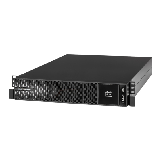
Control panel with LCD BYPASS BATTERY LINE FAULT Plastic front trim Fig. 1. Front view of 6 and 10kVA models. Fig. 2. Front view of the battery module. ISO PACK Fig. 3. Front view of the isolation transformer. SALICRU... - Page 9 Communication bus Fans RS-232 port COM port Digital Smart slot for parallel systems input/output protective cover Manual Bypass auxiliary contact Output terminals, Connector for Input Current signal bus Connector for connection to for parallel systems earth, input external EPO switch external battery module Fig.
-
Page 10: Definition Of The Product
Before connecting a module or group of batteries to the device or another available module, it is necessary to check that the voltage value printed on the back of the device next to the battery connector is appropriate and that the polarity between the means of connection corresponds. SALICRU... -
Page 11: Operating Principle
(up to 3). Each battery module has clean power to the inverter. two connectors for easy connection to the device and other The design and construction of the SLC TWIN RT2 T UL series identical modules. UPS has been carried out in accordance with international N+X redundant parallel connection to increase reliability •... -
Page 12: Optional Extras
The most common use of these types of ports is to provide • the necessary information to the file-closing software. T.S.S. For more information, contact our or our nearest • distributor. SALICRU... -
Page 13: Installation
5. INSTALLATION. Read and respect the Safety Information, described Battery module: • ˆ in Chapter 2 of this document. Failure to obey some 1 battery module. – of the instructions described in this manual can result in a Information for warranty registration. –... -
Page 14: Transport To The Site
For all instructions regarding connections, refer to section • 5.2. Fig. 8. Set of feet with extensions. Place the UPS, battery module and isolation transformer up- • right between the two bases, similar to as shown in Fig. 9. SALICRU... -
Page 15: Mounting A Rack In A 19" Cabinet
To install the battery module and the transformer, follow the steps described above for the UPS until obtaining the assembly shown in Fig. 11. Fig. 9. Vertically mounted tower-type model. 5.1.5.3. Mounting a rack in a 19” cabinet. To mount a device in a 19” rack cabinet, proceed as follows •... -
Page 16: Preliminary Considerations Before Connection, Regarding
ˆ regulations of the destination country. communication units. Remove the fixing screws and The SLC TWIN RT2 T UL features terminals for the instal- plastic cover to enable it to be inserted. • lation of an external emergency power off button (EPO) or, It is recommended to use terminals on all of the ends of •... -
Page 17: Connection Of The Input And Output Of A 'Single' Device
5.2. CONNECTIONS. 5.2.1. Connection of the input and output of a ‘single’ device: As the device has Class I protection against elec- ˆ U (L) tric shock, it is essential to install a protective earth conductor (connect earth ( )). Connect this con- ductor before supplying voltage to the input terminals. -
Page 18: Connection Of The Ups' Output To The Isolation
In the case of a 208V input: In the case of a 240V input: Isolation transformer Isolation transformer Fig. 15. UPS - isolation transformer connection according to the input voltage. Fig. 16. Diagram for connection of the UPS to the battery module and isolation transformer. SALICRU... -
Page 19: Configuration Of The Output
5.2.2. Configuration of the output. The output of the UPS must be connected to the input of the isolation transformer (Fig. 16), with the output of the latter being the final output of the UPS system. We can opt for 4 different output configurations implementable in the isolation transformer: Option 1: There are 2 sets of outputs at 120V. - Page 20 UPS, we recommend distributing the output between the labelling and the instructions in this manual, power over at least four lines. Each of them will have a cir- labelling shall always prevail. cuit breaker with a value of one quarter of the rated power. SALICRU...
-
Page 21: Connection To External Batteries (Backup Extension
This type of output power distribution will ensure that a fault in any of the machines connected to the device that causes a short circuit does not affect more than the line that is faulty. The remaining connected loads will have continuity as- sured due to the tripping of the protection only in the line affected by the short circuit. -
Page 22: Manual Bypass Auxiliary Contact Terminals
(NO) contact of 24V DC and 1A. (Pay ATTENTION to the voltage and current applied.) The SLC TWIN RT2 T UL has a signal block through which • it is possible to activate the shutdown command for the UPS’s inverter when closing the circuit. -
Page 23: Connection Of The Power Cables
Diagram 1: Power cable connection Communication bus. Current signal bus Fig. 25. Communication and current signal connections for system in parallel. Diagram2: Wiring diagram of parallel system 5.2.8.3. Connection of the power cables. 2-7. Software Installation The following diagram shows the connection terminals of For optimal computer system protection, install UPS monitoring software to fully configure UPS shutdown. -
Page 24: Communication Port
The RS-232 port consists of the transmission of serial data • in such a way that a large amount of information can be sent through a communication cable with only 3 wires. The USB port is compatible with the USB 1.1 protocol for • communication software. SALICRU... -
Page 25: Considerations Before Startup With Connected Loads
Fig. 28. View of ViewPower’s main screen. Installation procedure: • Go to the web page: ˆ http://support.salicru.com Select the required operating system and follow the ˆ instructions described on the web page to download the software. 5.2.12. Considerations before startup with connected loads. -
Page 26: Operation
Set the device’s input circuit breaker to ‘On’. • Press the ‘ON’ button for more than 2 seconds, the audible • alarm will sound for 1 second and the UPS will start up. The fan or fans, depending on the model, will start to func- tion. SALICRU... -
Page 27: Operating Procedure For A Parallel System
6.3. OPERATING PROCEDURE FOR A PARALLEL SYSTEM. Proceed as follows: Press the ‘OFF’ button on all of the UPSs for more than ˆ The operating procedure established here is for devices 2 seconds to shut down the inverter in all of them. The •... -
Page 28: How To Replace A Faulty Ups In An Operational
The steps to follow to replace a UPS in a system consisting • of two or three units are the same as those for incorpo- rating a device, except for the difference in the type of ac- tion to be carried out. Proceed therefore as described in section 6.4. SALICRU... -
Page 29: Control Panel With Lcd
7. CONTROL PANEL WITH LCD. 7.1. GENERAL INFORMATION FOR THE SERIES. 7.1.1. Information represented by the display. Audible alarm Discharge time Fault information disabled information Information about the Battery charge level charge level connected information to the output Information on battery input and voltage Output voltage information... -
Page 30: Common Abbreviations Shown On The Display
Tab. 5. Abbreviations shown on the LCD. Parallel, 001 refers to the first. Emergency power off. Frequency. Load percentage. Escape. Upper voltage limit for transfer to battery mode. Lower voltage limit for transfer to battery mode. EPO normally open. EPO normally closed. Estimated backup time. SALICRU... - Page 31 7.2. CONTROL PANEL. 7.2.1. Audible alarms. The control panel consists of: • Possibility of Description Alarm modulation or tone Four buttons with the functions described in Tab. 6. ˆ muting A backlit LCD display. ˆ State of the UPS Four optical LEDS (see Tab. 8). ˆ...
- Page 32 If it is between 46 and 54Hz, it will be set at 50Hz, and, if it is between 56 and 64Hz at 60Hz. The fac- tory default setting is ATO. SALICRU...
- Page 33 Parameter 3 setting: Frequency mode. Code 05 - ECO mode selection. ˆ • Output frequency in CF mode or not CF mode setting. It is possible to choose between two options: CF. Sets the UPS to CF mode. With this option ac- –...
- Page 34 Code 10 - Reserved. • Fig. 45. Reserved for future options. ˆ Code 14 - Reserved. • Fig. 42. Reserved for future options. ˆ Fig. 46. Reserved for future options. ˆ SALICRU...
- Page 35 Code 17 - Battery module number setting. Parameter 2 setting: • ˆ Indicates battery capacity. The following values can – be selected: 7, 9, 10, 12, 17, 26, 40, 65, 100Ah. Parameter 3 setting: ˆ Indicates number of parallel battery branches. It –...
- Page 36 When the input voltage is within the predefined range of the device and the bypass is enabled, when the UPS is switched off, the device Description. enters bypass mode. The audible alarm modulated every two minutes is activated. Bypass mode LCD. SALICRU...
- Page 37 Operating mode / state With the UPS in AC mode or CF mode, press the ‘TEST’ button for more than 0.5 seconds. The audible alarm will beep and the battery test Description. will start. In the electric flow diagram of the display, the line between I / P and the inverter icon flashes for information purposes. This test is useful to check the battery state.
- Page 38 Battery disconnected. Modulated every second. BATT FAULT Battery overcharge. Modulated every second. EPO activated. Modulated every second. Fan fault / Modulated every second. TEMP Overtemperature. CHARGING Charger fault. Modulated every second. BATTERY Tab. 13. Warning or alert indicators. SALICRU...
- Page 39 T.S.S. ferent service lives are available upon request. If it is necessary to contact our Technical Service and Support SLC TWIN RT2 T UL series UPSs require minimum upkeep. T.S.S., provide the following information: • The batteries used in the standard models are lead acid, UPS model and serial number.
- Page 40 T.S.S. for the intervention of in the event of a fault. 8.4. TECHNICAL SERVICES NETWORK. Information about our national and international Technical (T.S.S.) Service and Support centres can be found on our website. SALICRU...
- Page 41 9. ANNEXES. 9.1. GENERAL TECHNICAL SPECIFICATIONS. Models. TWIN RT2 T UL Available power ratings (kVA / kW). 6 / 6 10 / 10 Technology. On-line double-conversion, PFC, double DC bus. Rectifier. Input type. Single-phase Number of cables. 3 cables - Phase R (L) + Neutral (N) and earth. Rated voltage.
- Page 42 (real time) samples are usually in a single device. The IGBT’s excitation circuit is similar to received from an analogue/digital converter (ADC). that of the MOSFET, while the conducting characteristics SALICRU...
- Page 43 are similar to those of the BJT. Interface. In electronics, telecommunications and • hardware, an interface (electronics) is the port (physical circuit) through which signals are sent or received from one system or subsystem to another. kVA. A volt-ampere is the unit used for apparent power in •...
- Page 44 : ....................................................................................................................................................................................................................................................................................................................................................................................................................................................................................................................................................................................................................................................................................................................................................................................................................................................................................................................................................................................................................................................................................................................................................................................................................................................................................................................................................SALICRU...
- Page 45 : ....................................................................................................................................................................................................................................................................................................................................................................................................................................................................................................................................................................................................................................................................................................................................................................................................................................................................................................................................................................................................................................................................................................................................................................................................................................................................................................................................................USER MANUAL SLC TWIN RT2 T UNINTERRUPTIBLE POWER SUPPLIES (UPS)
- Page 46 Avda. de la Serra 100 08460 Palautordera BARCELONA Tel. +34 93 848 24 00 Fax +34 93 848 22 05 sst@salicru.com SALICRU.COM Information about our technical service and support net- work (T.S.S.), sales network and warranty is available on our website: www.salicru.com...
Need help?
Do you have a question about the SLC TWIN RT2 T UL and is the answer not in the manual?
Questions and answers