Table of Contents
Advertisement
Quick Links
Advertisement
Table of Contents
Troubleshooting

Related Manuals for Salicru SLC TWIN PRO Series


Summary of Contents for Salicru SLC TWIN PRO Series
- Page 1 UNINTERRUPTIBLE POWER SUPPLY (UPS) + LIGHTING FLOW DIMMER STABILIZERS (ILUEST) + SWITCH MODE POWER SUPPLY + STATIC INVERTERS + PHOTOVOLTAIC INVERTERS + VOLTAGE STABILIZERS AND POWER LINE CONDITIONERS UNINTERRUPTIBLE POWER SUPPLY UPS SLC TWIN PRO series 4 to 20 kVA...
-
Page 3: Table Of Contents
Description of the available maintenance and service 4.3.8.2. Smart slot. contracts. 4.3.8.3. Relays interface (option). 7.5. Technical service network. 4.3.9. Software. 4.3.10. Considerations before starting up the connected loads. Annexes. 8.1. General technical specifications. Operating. 8.2. Glossary. 5.1. Commissioning. 5.1.1. Controls before commissioning. SALICRU... -
Page 4: Introduction
Yours sincerely. • «Earth bonding terminal». Connect the earth cable coming from the load and the external battery cabinet to SALICRU this terminal. • Preservation of the environment: The presence of ˆ The equipment here described can cause important this symbol in the product or in their associated physical damages due to wrong handling. -
Page 5: General Safety Warnings
• Cross cable sections used to supply the equipment and loads, connected loads, due to the protection tripping of the affected will be according to the nominal current stated in the nameplate line by the short-circuit only. label of the equipment, and respecting the Low Voltage Electro- SALICRU... -
Page 6: To Keep In Mind
• When replacing a fuse, do it for another of the same type, char- discharge of high voltage and it is restricted to qualified staff acteristics format and size. only. Do not open the equipment. • Under any concept the input power cord will be connected to the A part from the implicit stated risks, any action that make the output of the equipment, either directly or through other ways. -
Page 7: Safety Warning Regarding Batteries
Do not modify its length. • In those equipments requested without batteries, their ac- quisition, installation and connection of themselves will be done by the end-user and under his responsibility. Data concerning the batteries as regards to quantity, capacity and SALICRU... -
Page 8: Quality And Standard Guarantee
Quality and standard 2.3. Environment. guarantee. This product has been designed to respect the environment and has been manufactured in accordance with the standard ISO 14001. 2.1. Declaration of the management. Equipment recycling at the end of its useful life: Our company commits to use the services of authorised socie- Our target is the client’s satisfaction, therefore this Management ties and according to the regulations, in order to treat the recov-... -
Page 9: Presentation
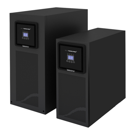
Figures regarding its main features or specifications can be checked in the nameplate of the equipment. Keep them in mind for its installation. Models from 4 to 10 kVA Models from 12 to 20 kVA Fig. 1. Front view from 4 to 20 kVA models. SALICRU... - Page 10 RS-232 RS-232 Protection cover for Protection cover for Fans smart slot Protection smart slot cover for Protection cover for Fans parallel port parallel port Protection cover for Protection cover for manual manual Bypass switch Bypass switch (maintenance) (maintenance) Input switch Input switch M1 Protection Protection cover for...
- Page 11 Battery switch Protection cover for power blocks Batteries module for models up to 10 kVA. Battery switch Power blocks Batteries module for models > 10 kVA. Fig. 3. Rear view batteries module. SALICRU...
-
Page 12: Nomenclature
3.2. Definition of the product. 3.2.1. Nomenclature. SLC-8000-TWIN/3 PRO (B1) WCO “EE29503” Special specifications of the client. “Made in Spain” marking in the UPS and its packaging (custom issue). Neutral brand equipment. No batteries and no space for installing them. Equipment with extra charger and external batteries to the UPS. -
Page 13: Operating Principle
• Easy firmware updating, no need to call to the Service and Thanks to the used technology, PWM (pulse width modulation) Technical Support (S.T.S.). and double conversion, UPS from SLC TWIN PRO series are • Simplified maintenance, which allows replacing the batteries compact, cold, silent and high efficiency. -
Page 14: Isolation Transformer
The isolation transformer can be installed at the input or output of the UPS from SLC TWIN PRO series and it will always be located out from the equipment enclosure. 3.4.2. External maintenance manual bypass. -
Page 15: Installation
UPS input and bypass line. any damage in transport (impact, drop, ...) and its features correspond with the ones in the order, so it is recommended to unpack the UPS and make a first visual inspection. SALICRU... -
Page 16: Storage
• In case of observing damages, make all pertinent claims to • Finally, shutdown the equipment, disconnect it and fit the UPS the transport agency or in their lack to our company. and batteries in their original packaging, noting the new bat- tery charge date on each respective label. -
Page 17: Transport To Location
(TWIN/3 PRO up to 10 kVA) or in the bypass line cover and the own covers. (TWIN/3 PRO > 10 kVA). When finalising the corresponding tasks the cover/s and their fixing screws will be fitted back. SALICRU... -
Page 18: Connection Of Bypass Power Block. Twin/3 Pro > 10 Kva Only
Connect the power supply cables to input power blocks R Operating: (L1), S (L2), T (L3) and N, by respecting the phase rotation If bypass thyristor is short-circuited and the UPS is working and neutral stated in the labelling of the equipment and in on double conversion mode (On-Line), the «Backfeed pro- this manual. -
Page 19: Connection To Output Power Block
UPS connection power block (TWIN/3 PRO up to 10 kVA). line affected by the short-circuit will trip its protection. UPS connection power block (TWIN PRO). UPS connection power block (TWIN/3 PRO > 10 kVA). Fig. 11. Connection power block. SALICRU... -
Page 20: Terminals For Epo (Emergency Power Off
4.3.5. Connection of main input earth Accumulator cabinet or modules have battery protection too, and in this case, they are duplicated. An internal ones terminal and the earth bonding through fuses with no access for the end-user and an addi- terminal tional ones by means of a two pole circuit breaker. -
Page 21: Connection In Parallel
• Respect the established procedure to make the connection of described in the previous sections of this chapter. the output (loads), which has been described in the previous sections of this chapter. SALICRU... -
Page 22: Communication Ports
the same card and to each one of them an alarm of the 8 • In parallel systems, the length and cross section of the available can be assigned (see table 5). cables that go from the switchgear panel till one of the UPSs and vice versa, will be the same for all of them without Also there are other three additional terminals with only one any exception. -
Page 23: Considerations Before Starting Up The Connected Loads
• Installation procedure: ˆ Go to website: http://support.salicru.com ˆ Choose the operating platform that you need and follow the instructions described in the web site to download the software. -
Page 24: Operating
Fan/s depending on the model, will be started up and the LCD panel will show the "SALICRU" brand logo . 5.2.4. UPS shutdown, without mains. Next, the main screen will be displayed after the equipment test. -
Page 25: Operative For A Parallel System
The acoustic alarm will beep for 3 seconds. The equipments that belong to the current parallel system will transfer to "Bypass mode". ˆ Put all the equipments on manual bypass. To do it re- SALICRU... -
Page 26: How To Replace A Faulty Ups From The Operating Parallel
5.5. How to replace a faulty UPS from • Remove the cover of the manual bypass in each UPS. • Transfer the equipments with the manual bypass ("BYPASS" the operating parallel system. position) to position "UPS". Do it in the switches of all equip- ments. -
Page 27: Transference To Normal Mode
Press over the start up key for more than 1 second in any of the UPSs and all of them will start up, finally the parallel system will be on "Normal mode” Load/s are protected by the parallel system again. SALICRU... -
Page 28: Control Panel With Lcd
Control panel with Table 6. Functionality of the buttons or keypad of the control panel. LCD. • The UPS has a control panel with the following parts: ˆ Four buttons or membrane keys, see table 6. ˆ A LCD panel with two colours backlight. By default, the text or graphics messages are shown in white colour over blue background. - Page 29 Para number over (UPS only 4.. 10 kVA Warning Blue Alarm Blue TWIN/3). TWIN). On maintain Bypass (UPS only 4.. 10 Alarm Blue kVA TWIN). Tabla 9. UPS status and color LCD display, as condition. On maintain Bypass (UPS only 8.. 20 Warning Blue kVA TWIN/3). SALICRU...
-
Page 30: Operating Modes Of The Equipment
• Immediately after the start up, the LCD panel shows the or phase to phase and neutral can be appreciated. SALICRU logo for few seconds and next the main screen • For more details about the representations in the LCD of the by default is displayed, where the status of the equipment is control panel, see next section 6.2. - Page 31 (50 or 60 Hz). When the input power supply fails, due to fault or wrong, the equipment will transfer to "Battery mode" to feed the load/s properly. Fig. 27. Overload screen. Fig. 24. Frequency converter mode screen. – This function can be activated through the settings SALICRU...
-
Page 32: Operating Of The Lcd Panel
6.3. Operating of the LCD panel. ˆ Battery test. The UPS is running a battery test. • Less in the main screen, which summarizes the UPS status, the user can get more useful information about the current conditions of the equipment, details of measures, event data logger, the own identification of the UPS, and change the settings to be adapted to the own needs, and optimise the function of the equipment. -
Page 33: Data Logger Submenu
> 1 sec. Press < 1 sec. Press < 1 sec. Fig. 32. Event logger submenu. Structure of main menu Structure of measurement submenu Press > 1 sec. Press < 1 sec. Press < 1 sec. Fig. 33. Measurement submenu screen. SALICRU... -
Page 34: Control Submenu
6.3.3. Data logger submenu. 6.3.5. Control submenu. • When pressing the key for less than 1 sec. from the "Event • When pressing the key the key for less than 1 sec. from log" screen, it is accessed to the event data logger structure this "Control"... -
Page 35: Identification Submenu
UPS and even they can affect or damage the load/s or battery. • Almost all the settings can only be done meanwhile the UPS is on bypass mode. SALICRU... -
Page 36: Maintenance, Warranty And Service
• UPS model and serial number. the stated in section 1.2.3.3. • Date when the problem occurred. • The UPSs from SLC TWIN PRO series only requires a minimum maintenance. The used battery in the standard • Complete description of the problem, including the infor- models is lead acid, sealed, VRLA and maintenance free. -
Page 37: Troubleshooting Guide. Warning Indications
ECO function is activated in the parallel Parallel in HE mode ECO function is not allowed in a parallel system Alarm code:EB system Parallel load UPS internal fault Consult with the S.T.S. unbalance Table 10. Troubleshooting guide. Warning indications. SALICRU... -
Page 38: Troubleshooting Guide. Fault Indications
7.2.2. Troubleshooting guide. Fault indications. Indication in the LCD Possible cause Solution TWIN PRO4-10 kVA TWIN/3 PRO 8-20 kVA Inverter Overload Inverter Overload Check the load and remove the non-critical ones Fault Overload Fault Check if any load is faulty or damaged Alarm code:42 Bypass Overload Byp Overload Fault... -
Page 39: Warranty Conditions
7.3.1. Covered product. • Check the fan status. • Bypass test. UPS SLC TWIN PRO series. • Make a general cleaning of the equipment. • Controlling the mechanical parts and temperatures. 7.3.2. Warranty terms. This way, it is guaranteed the perfect operating and the possible This product is guaranteed against any parts and/or labour defect coming faults are avoided. -
Page 40: Annexes
Annexes. 8.1. General technical specifications. Models: TWIN PRO TWIN/3 PRO ≤ 10 kVA TWIN/3 PRO > 10 kVA Available powers (kVA / kW) 4 / 3.6 5 / 4.5 6 / 5.4 8 / 7.2 10 / 9 8 / 7.2 10 / 9 12 / 10.8 15 / 13.5... -
Page 41: Glossary
Interference or RFI. This perturbation can derate or from the highest potential point to the lowest one. Although, limit the efficiency of the circuit. usually the direct current is identified with the constant cur- rent (for example the one supplied by the battery), it is con- SALICRU... - Page 42 • IGBT.- The Insulated Gate Bipolar Transistor is a semicon- of the input signal, this distortion is not so dissonant and it is ductor device that is used as a controlled switch in power elec- more difficult to detect. tronic circuits. This device has the feature of the gate signal of the effect field transistors with the capacity of high current and low voltage saturation of the bipolar transistor, combining an isolated FET gate for the input and a bipolar transistor as switch...
- Page 43 : ............................................................................................................................................................................................................................................................................................................................................................................................................................................................................................................................................................................................................................................................................................................................................................................................................................................................................................................................................................................................................................................................................................................................................................................................................ SALICRU...
- Page 44 BARCELONA Tel. +34 93 848 24 00 902 48 24 00 (Only Spain) Fax. +34 94 848 11 51 salicru@salicru.com Tel. (S.T.S.) +34 93 848 24 00 902 48 24 01 (Only Spain) Fax. (S.T.S.) +34 93 848 22 05 sst@salicru.com...
Need help?
Do you have a question about the SLC TWIN PRO Series and is the answer not in the manual?
Questions and answers