Advertisement
Table of Contents
Advertisement
Table of Contents

Related Manuals for Salicru SLC-700-TWIN RT2


Summary of Contents for Salicru SLC-700-TWIN RT2
- Page 1 USER MANUAL UNINTERRUPTIBLE POWER SUPPLY SYSTEMS (UPS) SLC TWIN RT2 0,7.. 10 kVA...
-
Page 2: Table Of Contents
Rotation of the control panel with LCD display. 6.2.2. UPS start-up without mains voltage. 5.1.5.2. Vertical tower-type mounting. 6.2.3. UPS shutdown with mains voltage. 5.1.5.3. Vertical tower-type mounting with backup extension (battery module). 6.2.4. UPS shutdown without mains voltage. SALICRU... -
Page 3: Operation
6.3. OPERATING PROCEDURE FOR A PARALLEL SYSTEM (ONLY 8.3.2. Exclusions. IN 4 TO 10 KVA MODELS). 8.4. TECHNICAL SERVICES NETWORK. 6.4. HOW TO ADD A UPS TO A SYSTEM IN PARALLEL 9. ANNEXES. OPERATION OR TO A FUNCTIONING SINGLE UPS (ONLY IN 4 TO 10 KVA MODELS). -
Page 4: Introduction
We remain at your disposal for any additional information or queries that you may wish to make. Yours sincerely. SALICRU The equipment described herein is capable of causing • significant physical damage in the event of improper handling. -
Page 5: Safety Information
For more information, see section 1.1.1 of document EK266*08 The documentation of any standard equipment is available to the "Safety instructions". customer on our website for download (www.salicru.com). For devices “powered by socket”, this is the website for • “Safety Instructions”... -
Page 6: Quality Assurance And Standards
It is not appropriate to use this equipment in basic life support applications (BLS), where a failure of the former can render vital equipment out of service or significantly affect its safety or effectiveness. It is also SALICRU... -
Page 7: Presentation
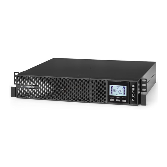
4. PRESENTATION. 4.1. VIEWS. 4.1.1. Views of the device. In Fig. 1 to Fig. 4, illustrations of the device are shown according to box size in relation to the power rating of the model. However, because the product is constantly evolving, discrepancies or slight contradictions may arise. - Page 8 Current signal bus for Manual Bypass Output, earth, Connector for Input parallel systems auxiliary contact. input terminals external EPO switch Standard 4 to 10 kVA models, represented with battery module Fig. 2. Rear view of 4 to 10 kVA models. SALICRU...
- Page 9 Battery module input Output connector for VDC protection connector battery module Battery module for 0.7 to 3 kVA devices Earth connection Battery module VDC protection connector Battery module for 4 to 10 kVA devices Battery module connector Fig. 3. Rear view of battery modules for extended backups. Output IEC Output IEC Output circuit...
-
Page 10: Definition Of The Product
Accessories such as screws, cables and battery corresponds. connection plates are considered optional and For more information, see Chapter 9 of this document. can be supplied upon request. SALICRU... -
Page 11: Operating Principle
4.3. OPERATING PRINCIPLE. Even if the LCD display on the backlit control panel shows messages, it does not mean that the inverter is This manual describes the installation and operation of SLC operational. It is switched on by pressing the ‘ON’ TWIN RT2 series UPSs as devices that can be independently button on the control panel, see Chapter 6. -
Page 12: Optional Extras
SLC-6000-TWIN RT2 SLC-8000-TWIN RT2 4.5.3.1. Integration into computer networks using an SNMP SLC-10000-TWIN RT2 adapter. SLC-700-TWIN RT2 (B0) SLC-1000-TWIN RT2 (B0) Large computer systems based on LANs and WANs that SLC-1500-TWIN RT2 (B0) integrate servers in different operating systems must provide SLC-2000-TWIN RT2 (B0) the system manager with ease of control and administration. - Page 13 5. INSTALLATION. Optional battery module for 0.7 to 3 kVA UPS: ˆ 1 battery module. – Read and respect the Safety Information, described Information for warranty registration. – • in chapter 2 of this document. Failure to obey some 2 metal pieces for use as handles and screws for –...
- Page 14 (greater number of battery modules). Follow the instructions indicated in the sections relating to SALICRU...
- Page 15 and install them to obtain two bases to hold the device and the battery module. Place the UPS and battery module upright between the two • bases (see Fig. 7) and at a distance of 70 mm from each end, similar to as shown in Fig. 7. Fig.
- Page 16 5.1.5.4 or 5.1.5.5 for everything related to the guides. Place the PDU onto the guides and insert it all the way ˆ to the back. Fix it to the cabinet frame using the screws supplied ˆ with the handles. SALICRU...
- Page 17 In parallel systems, the length and cross section of • the cables that run from the distribution or manual bypass board to each UPS and from these to the board will be the same for all of them without exception. The cross section of the cables must always be considered •...
- Page 18 To access the signal block, it is necessary to remove its protective cover. Slot for the integration of one of the optional electronic ˆ communication units. Remove the fixing screws and plastic cover to enable it to be inserted. SALICRU...
- Page 19 The IEC connectors indicated in Fig. 2 as ‘non-critical loads’ can be programmed as such through the control panel. In this case, the backup of the batteries for the loads connected to the IEC connectors indicated in Fig. 2 as ‘critical loads’...
- Page 20 Model earth connection terminal ( of batteries DC voltage (V) Current (A) SLC-700-TWIN RT2 As the device has Class I protection against electric • SLC-1000-TWIN RT2 shock, it is essential to install a protective earth (12 V x 3) = 36 V...
- Page 21 5.2.6. Terminals for digital input and output to relay. Only in auxiliary bypass contact to the block of the same models with power ratings > 3 kVA. functionality on the manual bypass board. This will prevent any incorrect action on the manual bypass disconnector The device has a four-terminal connector for a digital input when the UPS is running from causing total or partial failure •...
- Page 22 Interface to relays to terminals, not programmable. ˆ cables of the device must be less than 20%. SNMP adapter. ˆ When the distance between the UPSs in parallel and Modbus RS485 adapter. ˆ ˆ SALICRU...
- Page 23 Fig. 20. View of ViewPower’s main screen. Installation procedure: • Go to the web page: ˆ http://support.salicru.com Select the required operating system and follow the ˆ instructions described on the web page to download the software. USER MANUAL...
-
Page 24: Ups Shutdown Without Mains Voltage
A few seconds later, the LCD screen turns off and the entire device will be out of service. To leave the assembly completely isolated, turn the input • and output switches of the board to ‘Off’. SALICRU... - Page 25 6.3. OPERATING PROCEDURE FOR A PARALLEL SYSTEM Since it is necessary to change the parallel bus connection • (ONLY IN 4 TO 10 KVA MODELS). to incorporate the new device into the system (cable with DB15 connectors), it will be necessary to switch the In parallel systems, check that the programming of Output 2 powering of the loads to the manual bypass.
- Page 26 The steps to follow to replace a UPS in a system consisting • of two or three units are the same as those for incorporating a device, except for the difference in the type of action to be carried out. Proceed therefore as described in section 6.4. SALICRU...
- Page 27 7. CONTROL PANEL WITH LCD DISPLAY. 7.1. GENERAL INFORMATION FOR THE SERIES. 7.1.1. Information represented by the display. Audible alarm Discharge time Fault information disabled information Information about Information about the charge level battery charge level connected to the output Input voltage and battery information Output voltage...
- Page 28 Output voltage Parallel, 001 refers to the first. Emergency power off. Frequency. Load percentage. Escape. Upper voltage limit for transfer to battery mode. Lower voltage limit for transfer to battery mode. EPO normally open. EPO normally closed. Estimated backup time. SALICRU...
- Page 29 7.2. CONTROL PANEL FOR MODELS UP TO 3 KVA. 7.2.2. Audible alarms. 7.2.1. Composition of the control panel with LCD display. Possibility of Description Alarm modulation or tone muting The control panel consists of: • State of the UPS Three buttons with the functions described in Tab. 6. ˆ...
- Page 30 (3 x 18 Ah) = 54 Ah (value for parameter 12). are indicated in the following Tab. 9 and Tab. 10. Example for an SLC 1500 TWIN RT2 and backup extension module 698BU000003: 9 Ah + 18 Ah = 27 Ah (value for parameter 12). SALICRU...
- Page 31 The values indicated with(*) are factory default settings. • All settings can be carried out in operation with bypass parameter ‘06’ • either enabled or disabled, corresponding respectively to ‘ByPA’ normal mode or ‘STby’. To carry out any modification of the configuration, follow the indicated •...
- Page 32 When the input voltage is within the range but the UPS is overloaded, the system will automatically transfer to bypass mode or the transfer Description. to this mode can be forced through the front panel. The audible alarm beeps every 10 seconds. Bypass mode LCD display. SALICRU...
- Page 33 Operating mode / state Description. When an error occurs, the ERROR icon and the fault code are displayed. Error or fault state LCD display. Tab. 11. Operating modes. 7.2.4.3. Warning or alert codes. 7.2.4.5. Warning or alert indicators. Code Warning or alert description Code Icon (flashing) Audible alarm...
- Page 34 (CF) Working mode of the UPS as a frequency converter, in the static bypass it is disabled. Parameter 3 Parameter 2 Tab. 15. Functionality of the control panel buttons. Fig. 26. Arrangement of the parameters on the LCD display. SALICRU...
- Page 35 Parameter 1: Code 02 - Output frequency. • • Code of the settings menu. For more information consult Tab. 18. Parameters 2 and 3 are the configuration or value options • for each settings menu. Select with buttons ‘ ’ or ‘ ’...
- Page 36 At this point, manual switch to bypass is understood as being that which users perform on the UPS. For example, pressing the OFF button on the front of the device when it is in AC mode transfers the load to the static bypass. Fig. 35. SALICRU...
- Page 37 Parameter 2 setting. HS.H In correctly configured parallel UPS systems, the acronym ˆ • Enabling or disabling the Hot standby function. ‘PAR’ will be displayed in the place of the parameter 2 – Parameter 3 setting: variable and the number corresponding to the device of the ˆ...
- Page 38 When the input voltage is within the predefined range of the device and the bypass is enabled, when the UPS is switched off, the device Description. enters bypass mode. The audible alarm modulated every two minutes is activated. Bypass mode LCD display. SALICRU...
- Page 39 Operating mode / state With the UPS in AC mode or CF mode, press the ‘TEST’ button for more than 0.5 seconds. The audible alarm will beep and the battery test Description. will start. In the electric flow diagram of the display, the line between I / P and the inverter icon flashes for information purposes. This test is useful to check the battery state.
- Page 40 Perform the above steps in reverse to return the – device to how it was at the start, including start-up. UPS with batteries and electronics in separate boxes. ˆ Shut down the loads and device completely. – Disconnect the SLC TWIN RT2 from the mains. – SALICRU...
- Page 41 8.2.1. Troubleshooting guide for devices up to 3 kVA. Symptom Possible cause Solution Check that the power cables are firmly connected to The power cable is not connected correctly. the mains. No alarms or indications on the LCD display and mains voltage normal.
- Page 42 SALICRU...
-
Page 43: General Technical Specifications
9. ANNEXES. 9.1. GENERAL TECHNICAL SPECIFICATIONS. Models. TWIN RT2 Available power ratings (kVA / kW). Technology. On-line double-conversion, PFC, double DC bus. Rectifier. Input type. Single-phase. Number of cables. 3 cables - Phase R (L) + Neutral (N) and earth. Rated voltage. - Page 44 (for example, that supplied by a battery), electromagnetic interference (EMI), which is the disturbance any current that always maintains the same polarity is that occurs in a radio receiver or in any other electrical continuous. circuit caused by electromagnetic radiation coming from an SALICRU...
- Page 45 external source. Electromagnetic interference is also known SCR.- Silicon controlled rectifier, commonly known as a • as radio frequency interference (RFI). This disturbance can thyristor, a 4-layer semiconductor device that works as an interrupt, degrade or limit the performance of the circuit. almost ideal switch.
- Page 46 : ....................................................................................................................................................................................................................................................................................................................................................................................................................................................................................................................................................................................................................................................................................................................................................................................................................................................................................................................................................................................................................................................................................................................................................................................................................................................................................................................................................SALICRU...
- Page 47 : ....................................................................................................................................................................................................................................................................................................................................................................................................................................................................................................................................................................................................................................................................................................................................................................................................................................................................................................................................................................................................................................................................................................................................................................................................................................................................................................................................................USER MANUAL SLC TWIN PRO2 UNINTERRUPTIBLE POWER SUPPLY SYSTEMS (UPS)
- Page 48 Avda. de la Serra 100 08460 Palautordera BARCELONA Tel. +34 93 848 24 00 Fax +34 93 848 22 05 services@salicru.com SALICRU.COM The Technical Service and Support (T.S.S.) network, Com- mercial network and warranty information are available in website: www.salicru.com...
Need help?
Do you have a question about the SLC-700-TWIN RT2 and is the answer not in the manual?
Questions and answers