Advertisement
Quick Links
Advertisement

Subscribe to Our Youtube Channel
Related Manuals for Salicru SLC TWIN RT2


Summary of Contents for Salicru SLC TWIN RT2
- Page 1 USER MANUAL UNINTERRUPTIBLE POWER SUPPLY SYSTEMS (UPS) SLC TWIN RT2 0,7.. 10 kVA...
-
Page 2: Safety Information
6.1.1. Checks before start-up. 5.1.5. Siting, immobilising and considerations. 6.2. UpS START-Up And ShUTdown. 5.1.5.1. Rotation of the control panel with LCd display. 6.2.1. UpS start-up with mains voltage. 5.1.5.2. vertical tower-type mounting. 6.2.2. UpS start-up without mains voltage. SALICRU... - Page 3 8.2. UpS TRoUbLeShooTIng gUIde. 8.2.1. Troubleshooting guide for devices up to 3 kvA. 8.2.2. Troubleshooting guide for 4 kvA to 10kvA devices. USER MANUAL SLC TWIN RT2 UnInTeRRUpTIbLe poweR SUppLy SySTemS (UpS)
- Page 4 SALICRU The equipment described herein is capable of causing • significant physical damage in the event of improper handling.
- Page 5 Cd-Rom or pen drive in a safe and easy-to-access place, for any future queries or doubts that may arise. The following terms are used interchangeably in the document to refer to: ‘SLC TWIN RT2’, ‘TWIN RT2’, ‘TWIN’, ‘RT2’, ‘device’, • ‘unit’ and ‘UPS’ - Uninterruptible power supply.
-
Page 6: Quality Assurance And Standards
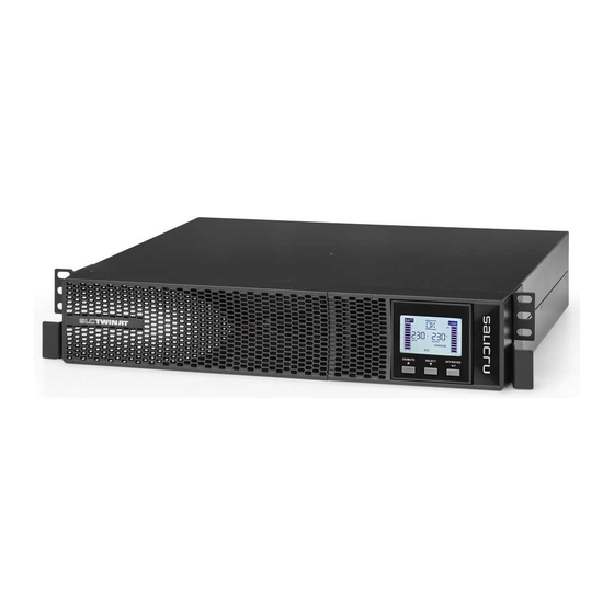
In a residential environment, this product may cause radio interference, in which case the user must take additional measures. SLC TwIn RT2 4.. 10 kvA. This is a category C3 UpS. This is a product for commercial and industrial application in the second environment; Installation restrictions or additional measures may be necessary to avoid disturbances. - Page 7 4 to 10 kvA models plastic front trim battery module for 0.7 to 10 kvA models Fig. 1. Front view of 0.7 to 10 kVA models and their battery modules for extended backups. USER MANUAL SLC TWIN RT2 UnInTeRRUpTIbLe poweR SUppLy SySTemS (UpS)
- Page 8 Current signal bus for manual bypass output, earth, Connector for Input parallel systems auxiliary contact. input terminals external epo switch Standard 4 to 10 kvA models, represented with battery module Fig. 2. Rear view of 4 to 10 kVA models. SALICRU...
- Page 9 4 to 6 kvA devices output IeC output IeC output IeC connectors connectors connectors pdU for 8 to 10 kvA devices output circuit breaker Fig. 4. Front view of PDU (power distribution unit). USER MANUAL SLC TWIN RT2 UnInTeRRUpTIbLe poweR SUppLy SySTemS (UpS)
- Page 10 Accessories such as screws, cables and battery corresponds. connection plates are considered optional and For more information, see Chapter 9 of this document. can be supplied upon request. SALICRU...
- Page 11 • The design and construction of the SLC TwIn RT2 series UpS modules in rack format. each battery module has two has been carried out in accordance with international standards.
- Page 12 4.5.2. exterior manual maintenance bypass. The purpose of this option is to electrically isolate the device from the mains and the critical loads without cutting the power to the latter. In this way, maintenance or repair operations on SALICRU...
-
Page 13: Installation
UpS as a tower (vertical For devices that contain pb-Ca batteries, the • position). charging times indicated in Tab. 2 of document ek266*08, determined by the temperature to which they USER MANUAL SLC TWIN RT2 UnInTeRRUpTIbLe poweR SUppLy SySTemS (UpS) - Page 14 (greater number of battery modules). Follow the instructions indicated in the sections relating to SALICRU...
- Page 15 Rotate the control panel according to section 5.1.5.1. • Take the 4 plastic pieces in the form of an angle supplied • with the UpS and the two supplied with the battery module, USER MANUAL SLC TWIN RT2 UnInTeRRUpTIbLe poweR SUppLy SySTemS (UpS)
- Page 16 5.1.5.4 or 5.1.5.5 for everything related to the guides. place the pdU onto the guides and insert it all the way ˆ to the back. Fix it to the cabinet frame using the screws supplied ˆ with the handles. SALICRU...
- Page 17 All values are calculated for a maximum total cable length of 30 m SLC TwIn RT2 devices from 0.7 to 3 kvA incorporate the • between the distribution board, equipment and loads. batteries in the same box as the device, except for b0, b1 For longer lengths correct the cross sections to avoid and higher power models.
- Page 18 To access the signal block, it is necessary to remove its protective cover. Slot for the integration of one of the optional electronic ˆ communication units. Remove the fixing screws and plastic cover to enable it to be inserted. SALICRU...
- Page 19 SLC TwIn RT2 devices from 0.7 to 3 kvA incorporate the • the amount of power they absorb from the UpS.
- Page 20 To recover the normal operating state of the UpS, it is • necessary to insert the connector with the jumper in its receptacle or deactivate the epo button. The device will be operational. Fig. 13. Connection to battery modules. Fig. 14. Connector for external EPO. SALICRU...
- Page 21 It is ESSENTIAL, as a safety measure for the Fig. 17. Communication and current signal connections • for system in parallel. assembly, including the loads, to connect the UpS’s USER MANUAL SLC TWIN RT2 UnInTeRRUpTIbLe poweR SUppLy SySTemS (UpS)
- Page 22 Interface to relays to terminals, not programmable. ˆ cables of the device must be less than 20%. Snmp adapter. ˆ when the distance between the UpSs in parallel and modbus RS485 adapter. ˆ ˆ SALICRU...
- Page 23 Fig. 20. View of ViewPower’s main screen. Installation procedure: • go to the web page: ˆ http://support.salicru.com Select the required operating system and follow the ˆ instructions described on the web page to download the software. USER MANUAL SLC TWIN RT2 UnInTeRRUpTIbLe poweR SUppLy SySTemS (UpS)
-
Page 24: Operation
• press the ‘on’ button for more than 2 seconds, the or manual bypass board and those on each UpS in 4 to • audible alarm will sound for 1 second and the UpS will 10 kvA. start up. SALICRU... - Page 25 ‘normal mode’. switch to ‘bypass mode’. USER MANUAL SLC TWIN RT2 UnInTeRRUpTIbLe poweR SUppLy SySTemS (UpS)
- Page 26 The steps to follow to replace a UpS in a system • consisting of two or three units are the same as those for incorporating a device, except for the difference in the type of action to be carried out. proceed therefore as described in section 6.4. SALICRU...
- Page 27 0-25 %, 26-50 %, 51-75 % and 76-100 frequency. Tab. 4. Information shown on the LCD panel of the control Information about programmable outputs panel and its meaning. Indicates that the programmable outputs are activated. USER MANUAL SLC TWIN RT2 UnInTeRRUpTIbLe poweR SUppLy SySTemS (UpS)
- Page 28 001 refers to the first. emergency power off. Frequency. Load percentage. escape. Upper voltage limit for transfer to battery mode. Lower voltage limit for transfer to battery mode. epo normally open. epo normally closed. estimated backup time. SALICRU...
- Page 29 Tab. 8 shows a summary of parameter 1’s adjustable codes for each operating mode and Fig. 24 shows the structure of the menu tree with the operating mode for the settings. USER MANUAL SLC TWIN RT2 UnInTeRRUpTIbLe poweR SUppLy SySTemS (UpS)
- Page 30 (3 x 18 Ah) = 54 Ah (value for parameter 12). are indicated in the following Tab. 9 and Tab. 10. example for an SLC 1500 TwIn RT2 and backup extension module 698bU000003: 9 Ah + 18 Ah = 27 Ah (value for parameter 12). SALICRU...
- Page 31 Time shown Shows available backup time. Shows elapsed backup time. configuration Fig. 24. Settings menu. USER MANUAL SLC TWIN RT2 UnInTeRRUpTIbLe poweR SUppLy SySTemS (UpS)
- Page 32 UpS is overloaded, the system will automatically transfer to bypass mode or the transfer description. to this mode can be forced through the front panel. The audible alarm beeps every 10 seconds. bypass mode LCd display. SALICRU...
- Page 33 2 seconds output overload Charger fault Input overcurrent Tab. 14. Warning or alert indicators. Tab. 13. Error or fault code. USER MANUAL SLC TWIN RT2 UnInTeRRUpTIbLe poweR SUppLy SySTemS (UpS)
- Page 34 (Cf) working mode of the UpS as a frequency converter, in the static bypass it is disabled. Tab. 15. Functionality of the control panel buttons. parameter 3 parameter 2 Fig. 26. Arrangement of the parameters on the LCD display. SALICRU...
- Page 35 It is possible to choose one of the following values for the output voltage between phase and neutral: (*) If ATo is selected in parameter 2, parameter 3 will 208, 220, 230 or 240 v. display the current frequency. – USER MANUAL SLC TWIN RT2 UnInTeRRUpTIbLe poweR SUppLy SySTemS (UpS)
- Page 36 At this point, manual switch to bypass is understood as being that which users perform on the UpS. For example, pressing the oFF button on the front of the device when it is in AC mode transfers the load to the static bypass. Fig. 35. SALICRU...
- Page 37 Any alteration of the battery pack will entail a readjustment, so it will be necessary to adapt the value in the event of future expansions. USER MANUAL SLC TWIN RT2 UnInTeRRUpTIbLe poweR SUppLy SySTemS (UpS)
- Page 38 UpS is switched off, the device description. enters bypass mode. The audible alarm modulated every two minutes is activated. bypass mode LCd display. SALICRU...
- Page 39 Low voltage in the inverter Inverter output short-circuited ChARGING Charger fault modulated every 1 seconds negative power fault at the output. BATTERY battery thyristor short-circuited. Inverter relay short-circuited. Tab. 22. Warning or alert indicators. USER MANUAL SLC TWIN RT2 UnInTeRRUpTIbLe poweR SUppLy SySTemS (UpS)
-
Page 40: Maintenance, Warranty And Service
Using the Tab. 23 and Tab. 24 troubleshooting guides, try SLC TwIn RT2 series UpSs require minimum upkeep. to resolve the issue and, if it persists, consult our Technical •... - Page 41 The charger does not provide output and the battery voltage Contact the distributor or seller or, failing that, our same time, the audible alarm sounds continuously. is less than 10 v per element. T.S.S. Tab. 23. Troubleshooting guide. USER MANUAL SLC TWIN RT2 UnInTeRRUpTIbLe poweR SUppLy SySTemS (UpS)
- Page 42 8.3.2. exclusions. Our company will not be bound by the warranty if it notices that the defect in the product does not exist or was caused by improper use, negligence, improper installation and/or SALICRU...
- Page 43 20 mv per battery / ºC for temperature > 25 ºC. Optional internal battery charger (B1). maximum charge current. 12 A Other functions. Cold start. emergency power off. Frequency converter. USER MANUAL SLC TWIN RT2 UnInTeRRUpTIbLe poweR SUppLy SySTemS (UpS)
- Page 44 Filter capable of significantly reducing • current (for example, that supplied by a battery), any current electromagnetic interference (emI), which is the disturbance that always maintains the same polarity is continuous. that occurs in a radio receiver or in any other electrical SALICRU...
- Page 45 USER MANUAL SLC TWIN RT2 UnInTeRRUpTIbLe poweR SUppLy SySTemS (UpS)
- Page 46 : ....................................................................................................................................................................................................................................................................................................................................................................................................................................................................................................................................................................................................................................................................................................................................................................................................................................................................................................................................................................................................................................................................................................................................................................................................................................................................................................................................................SALICRU...
- Page 47 : ....................................................................................................................................................................................................................................................................................................................................................................................................................................................................................................................................................................................................................................................................................................................................................................................................................................................................................................................................................................................................................................................................................................................................................................................................................................................................................................................................................USER MANUAL SLC TWIN RT2 UnInTeRRUpTIbLe poweR SUppLy SySTemS (UpS)
- Page 48 100 08460 palautordera BARCELONA Tel. +34 93 848 24 00 Fax +34 93 848 22 05 services@salicru.com SALICRU.COM The Technical service and support (T.s.s.) network, Com- mercial network and warranty information are available in website: www.salicru.com...
Need help?
Do you have a question about the SLC TWIN RT2 and is the answer not in the manual?
Questions and answers