Table of Contents
Advertisement
Advertisement
Table of Contents
Troubleshooting

Related Manuals for Salicru SLC TWIN PRO series


Summary of Contents for Salicru SLC TWIN PRO series
- Page 1 USER'S MANUAL UNINTERRUPTIBLE POWER SUPPLY UPS SLC TWIN PRO series 4.. 20 kVA...
-
Page 3: Table Of Contents
Technical service network. 5.3.8.2. Smart slot. 5.3.8.3. Standard relays interface. DB9 connector (TWIN PRO 4.. 10 kVA Annexes. only). 9.1. General technical specifications. 5.3.8.4. Relays interface (option). 9.2. Glossary. 5.3.9. Software. 5.3.10. Considerations before starting up the connected loads. SALICRU... -
Page 4: Introduction
We remain at you entire disposal for any further information or any query you should wish to make. Yours sincerely. SALICRU SALICRU • The equipment here described can cause important phys- ical damages due to wrong handling. This is why, the in- stallation, maintenance and/or fixing of itself must be done by our staff or qualified personnel exclusively. -
Page 5: Information For Safety
2.1.1. Conventions and used symbols. Some symbols can be used and shown in the equipment and/or in the description of this user's manual. For more information, see section 1.1.1 of EK266*08 document as regards to «Safety instructions». SALICRU... -
Page 6: Quality And Standard Guarantee
Quality and standard Declaration of conformity CE of the product is at the client disposal under previous request to our headquarters offices. guarantee. 3.2.1. First and second environment. The following examples of environment cover the majority of UPS installations. 3.1. Declaration of the management. -
Page 7: Presentation
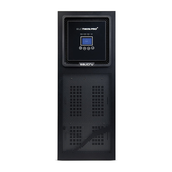
Figures regarding its main features or specifications can be checked in the nameplate of the equipment. Keep them in mind for its installation. Models from 4 to 10 kVA Models from 12 to 20 kVA Fig. 1. Front view from 4 to 20 kVA models. SALICRU... - Page 8 RS-232 RS-232 Relays Relays interface interface Protection cover for Protection cover for Fans smart slot Protection smart slot cover for Protection cover for Fans parallel port parallel port Protection cover for Protection cover for manual manual Bypass switch Bypass switch (maintenance) (maintenance) Input switch...
- Page 9 Battery switch Protection cover for power blocks Batteries module for models up to 10 kVA. Battery switch Power blocks Batteries module for models > 10 kVA. Fig. 3. Rear view batteries module. SALICRU...
-
Page 10: Nomenclature
4.2. Definition of the product. 4.2.1. Nomenclature. SLC-8000-TWIN/3 PRO (B1) WCO “EE29503” Special specifications of the client. “Made in Spain” marking in the UPS and its packaging (custom issue). Neutral brand equipment. No batteries and no space for installing them. Equipment with extra charger and batteries out from UPS. -
Page 11: Operating Principle
Thanks to the used technology, PWM (pulse width modulation) control panel and LCD with led indicators, user friendly. and double conversion, UPS from SLC TWIN PRO series are • Option cards are available to improve the communication ca- compact, cold, silent and high efficiency. -
Page 12: Isolation Transformer
The isolation transformer can be installed at the input or output of the UPS from SLC TWIN PRO series and it will always be located out from the equipment enclosure. 4.4.2. External maintenance manual bypass. -
Page 13: Installation
(impact, drop, ...) and its features have separate terminals for UPS input and bypass line. correspond with the ones in the order, so it is recommended to unpack the UPS and make a first visual inspection. SALICRU... -
Page 14: Storage
• In case of observing damages, make all pertinent claims to • Finally, shutdown the equipment, disconnect it and fit the UPS the transport agency or in their lack to our company. and batteries in their original packaging, noting the new bat- tery charge date on each respective label. -
Page 15: Transport To Location
(see Fig. 10). When finalising the corresponding tasks the cover/s and their fixing screws will be fitted back. Connect the power supply cables to input power blocks R (L1), S (L2), T (L3) and N, by respecting the phase rota- SALICRU... -
Page 16: Connection And Power Supply The Separate Static Bypass Line
tion and neutral stated in the labelling of the equipment and • To operate with separate bypass line, it is compulsory in this manual. If this rotation is not respected, the equipment to remove the cable bridge installed from factory be- will not work. -
Page 17: Connection To Output Power Block
UPS connection power block (TWIN/3 PRO up to 10 kVA). UPS connection power block (TWIN PRO). UPS connection power block (TWIN/3 PRO > 10 kVA). Fig. 11. Connection power block. SALICRU... -
Page 18: Terminals For Epo (Emergency Power Off
Minimum features of two Battery connection terminals Batteries poles protection switch Model Model x Nº) = cell In the external Voltage In the UPS Current (A) nominal floating battery module DC (V) SLC-4000-TWIN PRO SLC-4000-TWIN PRO SLC-5000-TWIN PRO Anderson connector SLC-5000-TWIN PRO SLC-6000-TWIN PRO Power block... -
Page 19: Connection In Parallel
This way, both the installation of any new UPS Fig. 13. Parallel installation of TWIN/3 PRO series > 10 kVA, in the parallel system is easier, and the risks due to electrical dis- with manual bypass and protection panel. SALICRU... -
Page 20: Communication Ports
5.3.8.3. Standard relays interface. DB9 connector • Respect the established procedure to make the connection of the battery modules for those equipments with extended back up time, (TWIN PRO 4.. 10 kVA only). which has been described in the previous sections of this chapter. •... -
Page 21: Considerations Before Starting Up The Connected Loads
• Installation procedure: UPS On Output ˆ Go to website: Mains fault Output http://support.salicru.com DB9 connector, standard. ˆ Choose the operating platform that you need and follow the instructions described in the web site to download the software. Description Nr pin Input/output ˆ... - Page 22 erating hours and the available autonomy time in the UPS. • Do not start up the equipment and loads completely till chapter 6 states it. Nevertheless, when it is done, it will be done gradually to avoid any problem, as minimum in the first commissioning. • If inductive loads with big inrush current apart from sensi- tive ones are required to be connected like laser printers or CRT monitors, keep in mind the start inrush currents of these...
-
Page 23: Operating
(M2) to "On". Fan/s depending on the model, will be started up and the 6.2.4. UPS shutdown, without mains. LCD panel will show the "SALICRU" brand logo . • Shutdown the load/s. Next, the main screen will be displayed after the equipment test. -
Page 24: Operative For A Parallel System
6.3. Operative for a parallel system. ˆ Put all the equipments on manual bypass. To do it re- move the cover from manual bypass switch, which is located at the back of each equipment and turn all the • The following operative, it is considered for equipments with switches to position "BYPASS". -
Page 25: How To Replace A Faulty Ups From The Operating Parallel
The The UPS still supplies output voltage, from mains directly complete parallel system will supply output voltage, through or through the static bypass line (TWIN/3 PRO > 10 kVA the bypass. only), through the manual bypass of the equipment. SALICRU... -
Page 26: Transference To Normal Mode
ˆ Also, if the protection panel has manual bypass switch, remove the mechanical lock and turn the switch "On" (BYPASS). In this case and in this case only, turn the output switch/es from distribution panel to "Off", depending if there is only one UPS or a system with "N" equipments in parallel. -
Page 27: Control Panel With Lcd
State Bypass abnormal. Blue Table 6. Functionality of the buttons or keypad of the control panel. State Utility abnormal. Blue State HE abnormal. Blue Site wiring fault (UPS only 4.. 10 kVA Warning Blue TWIN). SALICRU... - Page 28 Code Condition Description Color LCD Code Condition Description Color LCD Neutral or GND loss (UPS only 8.. 20 Ambient over temperature. (UPS only Warning Blue Alarm Blue kVA TWIN/3). 4.. 10 kVA TWIN). Battery disconnect (UPS only 4.. 10 Ambient NTC abnormal (UPS only 4.. State Blue Alarm...
-
Page 29: Operating Modes Of The Equipment
• Immediately after the start up, the LCD panel shows the or phase to phase and neutral can be appreciated. SALICRU logo for few seconds and next the main screen by default is displayed, where the status of the equipment is • For more details about the representations in the LCD of the... - Page 30 ˆ Bypass without output voltage: This function can be activated through the settings – of the control panel (by means of password) or by The UPS is running on bypass mode without output means of a suitable software (WinPower, ...) voltage.
-
Page 31: Operating Of The Lcd Panel
Estructura del menú principal UPS status summary Press > 1 sec. (Screen by default) Pulsar < 1 seg. Press < 1 sec. Alarm screen Parallel system screen Battery status screen (*) Accessible with S.T.S password only. Fig. 30. Main screen structure. SALICRU... -
Page 32: Data Logger Submenu
Structure of main menu Structure of UPS status menu Press > 1 sec. Press < 1 sec. UPS status summary (Screen by default) Press < 1 sec. Alarm screen Parallel system screen Battery status screens Fig. 31. UPS status screen. Structure of main menu Structure of Data logger submenu... -
Page 33: Control Submenu
Structure of main menu Structure of control submenutrol Press > 1 sec. Press < 1 sec. Press > 1 sec. Press < 1 sec. Press < 1 sec. (*) Accessible with S.T.S. password only Fig. 34. Control submenu screens. SALICRU... -
Page 34: Identification Submenu
7.4. Special functions Press < 1 sec. The UPS has some special functions, that could satisfy a special Press < 1 sec. application of the user. In case you require any of these special functionalists, contact with the S.T.S. to change the standard configuration from factory. Press <... -
Page 35: Maintenance, Warranty And Service
• UPS model and serial number. document EK266*08). • Date when the problem occurred. • The UPSs from SLC TWIN PRO series only requires a minimum maintenance. The used battery in the standard • Complete description of the problem, including the infor- models is lead acid, sealed, VRLA and maintenance free. -
Page 36: Troubleshooting Guide. Warning Indications
8.2.1. Troubleshooting guide. Warning indications. Indication in the LCD Possible cause Solution TWIN PRO 4-10 kVA TWIN/3 PRO 8-20 kVA Read EEPROM Error UPS internal fault Consult with the S.T.S. EPO Active Emergency Power Off EPO connector is open Check the status of the EPO connector Alarm code:71 On Maintain Bypass Manual bypass switch on BYPASS position... -
Page 37: Troubleshooting Guide. Fault Indications
(1 beep every 4 sec.) protection panel are turned "On" Batteries are not fully charged Back up time is shorter than the nominal Charge the batteries for 12 hours and check the capacity Faulty batteries Table 12. Troubleshooting guide. Other circumstances. SALICRU... -
Page 38: Warranty Conditions
8.3. WARRANTY CONDITIONS. 8.3.1. Warranty terms. The warranty conditions for the acquired product can be found in our website and in that you will be able to register it. It is recom- mended to do it as soon as possible in order to include it in the Technical Service &... -
Page 39: Annexes
3:1 Quantity of equipments in parallel connection Up to 4 SAI’s Static bypass Type Hybrid (thyristors in antiparallel + relay) Nominal voltage 208 / 220 / 230 / 240 V Nominal frequency 50 / 60 Hz ±4 Hz SALICRU... -
Page 40: Glossary
Models: TWIN PRO TWIN/3 PRO ≤ 10 kVA TWIN/3 PRO > 10 kVA Available powers (kVA / kW) (**) 4 / 3.6 5 / 4.5 6 / 5.4 8 / 7.2 10 / 9 8 / 7.2 10 / 9 12 / 10.8 15 / 13.5 20 / 18... - Page 41 • SCR.- Abbreviation of «Silicon Controlled Rectifier», called commonly as Thyristor: semiconductor device of 4 layer that works as almost an ideal switch. • THD.- They are the acronyms of «Total Harmonic Distor- tion». The total harmonic distortion is done when the output SALICRU...
- Page 42 : ............................................................................................................................................................................................................................................................................................................................................................................................................................................................................................................................................................................................................................................................................................................................................................................................................................................................................................................................................................................................................................................................................................................................................................................................................ USER MANUAL...
- Page 43 : ............................................................................................................................................................................................................................................................................................................................................................................................................................................................................................................................................................................................................................................................................................................................................................................................................................................................................................................................................................................................................................................................................................................................................................................................................ SALICRU...
- Page 44 Avda. de la Serra 100 08460 Palautordera BARCELONA Tel. +34 93 848 24 00 Fax +34 93 848 22 05 services@salicru.com SALICRU.COM The Technical Service & Support (T.S.S.) network, Com- mercial network and warranty information are available in website: www.salicru.com...
Need help?
Do you have a question about the SLC TWIN PRO series and is the answer not in the manual?
Questions and answers