Table of Contents
Advertisement
Quick Links
P
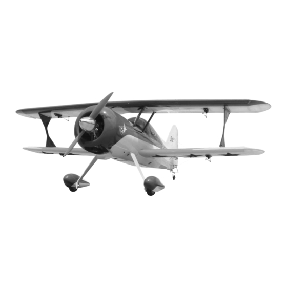
Aerobatic flying just doesn't get any better than this Pitts ARF. The classic lines of a biplane coupled with the
radial cowl, add excitement to the maneuvers you love, knife edge, split S, lumcevac, torque rolls, snaps, and
ground-hugging inverted flight. What's more, we've engineered this ARF to get you into the air with a minimum
of fuss. So take a few minutes to carefully read the introductory material and then get to work. You'll soon be
out at the field with a classic aerobatic champion!
A radio-controlled model is not a toy and is not intended for persons under 16 years old. Keep
this kit out of the reach of younger children, as it contains parts that could be dangerous. A radio-
controlled model is capable of causing serious bodily injury and property damage. It is the buyer's
responsibility to assemble this aircraft correctly and to properly install the motor, radio, and all other
equipment. Test and fly the finished model only in the presence and with the assistance of another
experienced R/C flyer. The model must always be operated and flown using great care and common
sense, as well as in accordance with the Safety Code of the Academy of Model Aeronautics (5151
Memorial Drive, Muncie, IN 47302, 1-800-435-9262). We suggest you join the AMA and become prop-
erly insured prior to flying this model. Also, consult with the AMA or your local hobby dealer to find an
experienced instructor in your area. Per the Federal Communications Commission, you are required
to use only those radio frequencies specified "for Model Aircraft."
Carl Goldberg Products, Ltd. has inspected and certified the components of this aircraft. The company urges the buyer to perform
his own inspection, prior to assembly, and to immediately request a replacement of any parts he believes to be defective for their
intended use. The company warrants replacement of any such components, provided the buyer requests such replacement with-
in a period of 90 days from the date of purchase and provided the defective part is returned, if so requested by the company.
No other warranty, expressed or implied, is made by the company with respect to this kit. The buyer acknowledges and under-
stands that it is his responsibility to carefully assemble the finished flying model airplane and to fly it safely. The buyer hereby
assumes full responsibility for the risk and all liability for personal or property damage or injury arising out of the buyer's use of the
components of this kit.
CARL GOLDBERG PRODUCTS, LTD.
P.O. Box 88 Oakwood GA 30566 Phone #678-450-0085 Fax # 770-532-2163 www.carlgoldbergproducts.com
i
t
t
P
i
t
t
©Copyright 2004 Carl Goldberg Products
s
M
s
M
WARNING
LIMITED WARRANTY
1
o
n
s
o
n
s
t
e
r
t
e
r
TM
Advertisement
Table of Contents

Related Manuals for Carl Goldberg Products Pitts Monster 12


Summary of Contents for Carl Goldberg Products Pitts Monster 12
- Page 1 LIMITED WARRANTY Carl Goldberg Products, Ltd. has inspected and certified the components of this aircraft. The company urges the buyer to perform his own inspection, prior to assembly, and to immediately request a replacement of any parts he believes to be defective for their intended use.
-
Page 2: Parts List
HARDWARE LIST PARTS LIST Cabane Struts (4) pcs. 1. Fuselage (12) 4-40x1/2” socket head screws 2. Cowl (4) #4 flat washers 3. Fin 4. Rudder I Struts (2) pcs. 5. I-Strut (2) (8) 4-40x1/2” socket head screws 6. Landing gear legs (2) (8) #4 Flat washers 7. - Page 3 Tail Wheel Motor Mounts (2) pcs (4) 8-32 x 1” Socket head bolts (1) tail wheel bracket (4) 8-32 x 1-1/4” Socket head bolts (1) 1-1/4” tail wheel (4) 8-32 T-nuts (2) #6x 3/4” sheet metal screws (4) aircraft lock nuts (2) #6 flat washers (12) #8 flat washers (2) springs...
- Page 4 Notice: Before starting be sure all parts have not been damaged during shipping. Once assembly has been started, all warrenty on parts are void. Before you begin assembling your Pitts ARF, take some COVERING time to read through this entire instruction book. It is The Pitts ARF is covered in a premium polyester film cho- designed to take you step-by-step through the process and...
- Page 5 ITEMS NEEDED TO COMPLETE THIS AIRCRAFT TOOLS AND SUPPLIES FOR ASSEMBLY RADIO GUIDANCE SYSTEM (4 CHANNEL MODELING OR UTILITY KNIFE MINIMUM REQUIRED WITH 7 SERVOS) WORK SURFACE (24" X70") You will need 7 servos for the plane. we rec- ELECTRIC DRILL ommend a standard servo on the throttle and 1/16”, 3/32”,1/8", 3/16”, 5/32”, 1/4”, 5/64”...
-
Page 6: Wing Assembly
WING ASSEMBLY Select the aileron for the wing on which you AILERON INSTALLATION are working and insert the exposed half of each hinge into the aileron slots. Slide the aileron toward the wing until no gap remains between the aileron and the wing. -
Page 7: Aileron Servo Installation
AILERON SERVO INSTALLATION AILERON CONTROL HORN INSTALLATION Note: The following pictures may not exactly match the hardware you are using. Always check the radio manufacturer's instructions when installing radio equipment. Collect the following items (8) 2-56 Golden Clevis (8) Clevis Clips (8) 2-56 Hex Nut (4) 2-56 x 1-3/4”... - Page 8 aileron plug cable ties Thread on to one end of a 2-56 x 1- 3/4” pushrod a nut and Golden Clevis. Mount the pushrod onto the the horn brack- Thread the other 2-56 clevis and nut on the other end. Install the rod in the control arm.
- Page 9 Bottom Wing Mounting Before mounting the tail the bottom wing should be installed. Collect the following items (1) Fuselage (1) Bottom wing (2) Wing dowels (8mm x 40mm) (2) 1/4” x 2” wing bolts (1) Trailing edge reinforcement plate. 1/8” ply. Use epoxy and glue the plate in place.
-
Page 10: Tail Construction
Tail Construction. Collect the following items (1) Stab (1) Fuselage (with bottom wing installed) (1) Fin When satisfied with the alignment, mark the outline of the fuselage on the stab top and bottom. Install stab in opening at rear of fuselage. Measure to make sure it is centered ( dimension B on each side should be the same. - Page 11 Mark here also Install the fin in the slot and check the align- ment. It can be adjusted a small amount by sanding the fin post area where it goes into the fuselage. It should not need any adjustment. Mark the outline of Install the 6-32 x 3”...
-
Page 12: Landing Gear Installation
Landing Gear Installation Install each axle using the locking nut. Be careful not to over tighten the nut, it looks like a large bolt but it has been drilled out for the axle and can Collect the following items. be broken if too much torque is applied. (2) Landing gear legs (6) 6-32X3/4”... - Page 13 Remove the wheel pant and drill a 5/32” hole The wheel pants have the 1/2” hole predrilled in at the location you marked. Insert the blind nut on each pant. The 1/8” hole for the mounting bolt must be the inside and pull it tight using the 4-40 mounting drilled.
- Page 14 Tail wheel Mounting Collect the following parts: (1) tail wheel bracket (1) tail wheel (2) 1/8” wheel collars (2) tail wheel springs (2) #6 x 1/2” sheet metal screws\ (2) #6 flat washers (2) nylon horn brackets- (1) #6-32 threaded rod 3” long Install one 1/8”...
- Page 15 Remove from the tailwheel springs approxi- mately 1/2” from the other side of the long wire. On the side of the spring that you just cut off, bend 2 or 3 coils of the spring out so that they can hook through the horn bracket. Twist the end of the spring on to the horn bracket.
- Page 16 Top Wing Mounting Locate the following items. (4) cabane struts (2) I-Struts (1) Top Wing (1) Bottom Wing (1) Fuselage (2) 1/4-20 x 2” wing bolts (20)4-40x 5/8” socket head screws (12) #4 flat washers (8) #4 aircraft lock nuts 4-40x5/8”...
- Page 17 Screw the eyebolts into the holes in the wing, they are set at a slight angle since the strut does not go perpendicular to the wings. The bottom set will lean out from the fuselage and the top wing will lean in toward the fuselage.
- Page 18 FLYING WIRES Locate the following parts Roll of braided cable The brackets go on each side of the fin and stab (8) metal plates with one bolt holding two on. There is a predrilled (4) 2-56 rigging couplers hole at each location. Hold up to a light to help locate (4) golden clevis the hole under the covering.
- Page 19 Insert the cable through the 1/16 OD x 1/4” brass tubing. Next thread the cable though the hole at the end of the 2-56 threaded rods and pass it back through the brass tube. Pass the cable through the brass tube, through the bracket on the stab and back through the brass tube.
- Page 20 Belly pan Mount the bottom wing in place. remove covering Remove the covering over the wing mount Place belly pan in place and mark the outline bolts access hole. on the bottom of wing. remove covering NO GLUE Remove belly pan and cut the covering away 1/16”...
-
Page 21: Engine Mounting
Engine Mounting Install the flat washer and silicone tubing on the 4-40 bolts. Collect the following items. Install the cowl with the 4-40 bolts and the predrilled holes in cowl. The blind nut are already (2) motor mounts installed in the fuselage. (4) 8-32x1”... - Page 22 The firewall has the thrust line marked on it. The center line is off set to the left to compensate for the right thrust. Center the motor mounts on the thrust line and mark the location of the mounting holes. Drill a 7/32”...
- Page 23 Fuel Tank Collect the following item (1) fuel tank 500cc (16.91 oz.) (1) rubber tank stopper (1) clunk (1) 3mm x 25mm screw (1) cap washer large (1) cap washer small (2) 3mm x 40mm brass tube (1) 3mm x 60mm brass tube Install the 4mm silicone tube to the short brass (1) silicone tube 4mm x 80mm tube and install the clunk to the other end of...
- Page 24 If you use a Y-S engine that pressurizes the tank, you should wrap the tank with nylon strapping Install the tank in the fuselage with the cap tape to make sure the pressure does not split the aligned in the hole in the firewall. Use foam rubber tank.
-
Page 25: Cowl Mounting
Cowl Mounting Collect the following items. (1) Cowl (4) 4-40 x 1” Socket Head Bolt (4) #4 Washer (4) 1/4” pieces silicone tubing (1) 4” x 12” Clear Plastic Unscrew the engine from the motor mounts. Place the cowl on the fuselage and fasten using the 4-40 x 1”... - Page 26 Install a golden clevis on the end of the 2-56 x 20 pushrod. Insert the pushrod in the hole in firewall that you drilled earlier. Slip the 5/32” nylon tube over pushrod and cut to length. It should extend out the hole in the firewall about 1/4”...
- Page 27 Assemble the 2-56 cable end same as shown above. Insert the 1/8” tubing into the rear cable exit hole. Push the tubing while guiding it through the fuselage. Thread the 2-56 end of the cable into the tub- Place the cable ends on your servo arm and ing and pull the tubing out the rear cable exit.
-
Page 28: Elevator Pushrod
Elevator Pushrod Take the shrink tubing and slide over the end of the dowel and wires. Let the tubing extend past the end of the dowel about 1/4”. Use a heat gun to shrink tight. If you don’t have a Collect the following items heat gun a match or lighter will work just be careful with the open flame. - Page 29 The receiver should be wrapped in at least 1” of Install a clevis on the 6” pushrod and attach foam rubber. You will need two Y-connectors here. to elevator arm on servo. Make a mark on the rod Plug one into the receiver, the other y-connector will and the dowel where they cross 1”...
- Page 30 It should hang level or slightly nose down. At the 5” in mark it will be nose heavy but will be really stable on the first flight. The Pitts will probably need weight in the tail to get it back to 6.22”. ©Copyright 2004 Carl Goldberg Products...
Need help?
Do you have a question about the Pitts Monster 12 and is the answer not in the manual?
Questions and answers