Table of Contents
Advertisement
Quick Links
CYW20829B0-P4TAI100, CYW20829B0-P4EPI100
A I R O C ™ B l u etooth ® L E m o d u l e
General description
The CYW20829B0-P4TAI100 is a fully integrated Bluetooth® LE wireless module. The CYW20829B0-P4TAI100
includes an onboard crystal oscillator, passive components, flash memory, and the CYW20829 silicon device.
Refer to the
CYW20829
module.
The CYW20829B0-P4TAI100 supports high-performance analog-to-digital conversion audio input, I
LIN for automotive use cases and other standard communication and timing peripherals. The
CYW20829B0-P4TAI100 includes a royalty-free Bluetooth® stack compatible with Bluetooth® 5.4 core spec in a
14.5 × 19 × 1.95 mm package.
The CYW20829B0-P4TAI100 includes 1 MB of onboard serial flash memory and is designed for standalone
operation. The CYW20829B0-P4TAI100 uses an integrated power amplifier to achieve Class I or Class II output
power capability.
The CYW20829B0-P4TAI100 is fully qualified by Bluetooth® SIG and is targeted at applications requiring
cost-optimized Bluetooth® wireless connectivity.
The CYW20829B0-P4TAI100 is offered in two certified versions CYW20829B0-P4TAI100, and
CYW20829B0-P4EPI100. The CYW20829B0-P4TAI100 includes an integrated trace antenna. The
CYW20829B0-P4EPI100 supports an external antenna through a RF solder pad output.
Module descri pti on
• Module size: 14.5 × 19 × 1.95 mm
• Bluetooth® 5.4 core spec qualified module
- QDID: TBD
- Declaration ID: TBD
• Certified to FCC, ISED, MIC, and CE regulations
• Castelated solder pad connections for ease-of-use
• 1-MB on-module serial flash memory
• Up to 26 GPIOs
• Temperature range: –30°C to +85°C
• 96-MHz Arm® Cortex®-M33 CPU with single-cycle multiply and memory protection unit (MPU)
• Maximum TX output power
- Programmable TX power: up to 10 dBm
• Bluetooth® LE connection range of up to 500 meters at 10 dBm
• RX sensitivity:
- LE-1 Mbps: –98 dBm
- LE-2 Mbps: –95 dBm
- Coded PHY 500 kbps (LE-LR): –101 dBm
- Coded PHY 125 kbps (LE-LR): –106 dBm
Note
1. Connection range tested module-to-module using Bluetooth® Low Energy Long Range Coded PHY technology
in full line-of-sight environment, free of obstacles or interference sources with output power of +10.0 dBm.
Actual range will vary based on end product design, environment, receive sensitivity, and transmit output
power of the central device.
Datasheet
www.infineon.com
datasheet for additional details on the capabilities of the silicon device used in this
Please read the Important Notice and Warnings at the end of this document
[1]
page 1
2
S/PCM, CAN,
002-39262 Rev. **
2024-01-23
Advertisement
Table of Contents

Related Manuals for Infineon AIROC CYW20829B0-P4TAI100


Summary of Contents for Infineon AIROC CYW20829B0-P4TAI100
-
Page 1: General Description
Actual range will vary based on end product design, environment, receive sensitivity, and transmit output power of the central device. Datasheet Please read the Important Notice and Warnings at the end of this document 002-39262 Rev. ** www.infineon.com page 1 2024-01-23... -
Page 2: Power Consumption
AIROC™ Bluetooth® LE module Power consumption Powe r consumpt ion • Bluetooth® LE current consumption - RX current: 5.6 mA @ LE 1 Mbps - TX current: 5.2 mA @ 0 dBm - Deep Sleep mode current with 64 KB SRAM retention: 4.5 µA - HIDOFF (Deep Sleep): 0.5 µA Functio nal capabilities •... -
Page 3: Benefits
AIROC™ Bluetooth® LE module Benefits • Security built into platform architecture - ROM-based root of trust via uninterruptible “Secure Boot” - Step-wise authentication of execution images - Secure execution of code in execute-only mode for protected routines - All debug and test ingress paths can be disabled - Up to four protection contexts (One available for customer code) - Secure debug support via authenticated debug token - Encrypted image support for external SMIF memory... -
Page 4: More Information
Infineon community: Whether you are a customer, partner, or a developer interested in the latest innovations, the developer community offers you a place to learn, share, and engage with both Infineon experts and other embedded engineers around the world. • Visit our... -
Page 5: Table Of Contents
AIROC™ Bluetooth® LE module Table of contents Table of contents General description ...........................1 Module description..........................1 Power consumption...........................2 Functional capabilities........................2 Benefits............................3 More information ..........................4 References............................4 Development environments .......................4 Technical support..........................4 Table of contents ..........................5 1 Overview ............................7 1.1 Functional block diagram............................7 1.2 Module description ..............................7 1.2.1 Module dimensions and drawing........................7 2 Pad connection interface.........................9... - Page 6 AIROC™ Bluetooth® LE module Table of contents 7.3.1 Sigma delta ADC..............................30 7.4 Programmable digital............................30 7.5 Fixed-function digital............................31 7.5.1 Timer/counter/pulse-width modulator (TCPWM) block..................31 7.5.2 Serial communication blocks (SCB)........................32 7.5.3 QSPI interface serial memory interface (SMIF)....................32 7.6 GPIO..................................33 7.7 Special-function peripherals..........................34 7.7.1 Audio subsystem..............................34 8 Electrical characteristics .......................35 8.1 Absolute maximum ratings ..........................35 8.2 Operating conditions............................36...
-
Page 7: Overview
1.2.1 Module dimensions and drawing Infineon reserves the right to select components from various vendors to achieve the Bluetooth® module functionality. Such selections will still guarantee that all mechanical specifications and module certifications are maintained. Designs should be held within the physical dimensions shown in the mechanical drawings in Figure 2. - Page 8 AIROC™ Bluetooth® LE module Overview Figure 2 for the mechanical reference drawing for CYW20829B0-P4TAI100. Figure 2 Module mechanical drawing Notes 2. No metal should be located beneath or above the antenna area. Only bare PCB material should be located beneath the antenna area. For more information on recommended host PCB layout, see “Recommended host PCB layout”...
-
Page 9: Pad Connection Interface
AIROC™ Bluetooth® LE module Pad connection interface Pad connection interface As shown in the bottom view of Figure 2, the CYW20829B0-P4TAI100 connects to the host board via solder pads on the backside of the module. Table 2 Figure 3 detail the solder pad length, width, and pitch dimensions of the CYW20829B0-P4TAI100 module. - Page 10 AIROC™ Bluetooth® LE module Pad connection interface Figure 4 Recommended host PCB keepout area around the CYW20829B0-P4TAI100 antenna Datasheet 002-39262 Rev. ** 2024-01-23...
-
Page 11: Recommended Host Pcb Layout
AIROC™ Bluetooth® LE module Recommended host PCB layout Recommended host PCB layout Figure 5 provides details that can be used for the recommended host PCB layout pattern for the CYW20829B0-P4TAI100. Dimensions are in millimeters unless otherwise noted. Pad length of 1.27 mm (0.64 mm from center of the pad on either side) shown in Figure 4 is the minimum recommended host pad length. -
Page 12: Module Connections
AIROC™ Bluetooth® LE module Module connections Module connections Table 3 details the solder pad connection definitions and available functions for the pad connections for the CYW20829B0-P4TAI100 module. Table 3 lists the solder pads on the CYW20829B0-P4TAI100 module, the silicon device pin, and denotes what functions are available for each solder pad. Table 3 Pin assignments Power... - Page 13 AIROC™ Bluetooth® LE module Module connections Table 4 GPIO pin descriptions Silicon Module Silicon Direction Power POR state Description pad name number pin name Default domain number P0.0 P0.0 Floating VDDO P0.1 P0.1 Floating VDDO P0.2 P0.2 Floating VDDO P0.3 P0.3 Floating VDDO...
- Page 14 Each port pin has multiple alternate functions. These are defined in Table Table 5 Multiple alternate functions Port/Pin Analog ACT #0 ACT #1 ACT #4 ACT #5 ACT #6 ACT #7 ACT #8 ACT #9 ACT #10 ACT #11 ACT #12 ACT #13 ACT #14 ACT #15...
- Page 15 (continued) Table 5 Multiple alternate functions Port/Pin Analog ACT #0 ACT #1 ACT #4 ACT #5 ACT #6 ACT #7 ACT #8 ACT #9 ACT #10 ACT #11 ACT #12 ACT #13 ACT #14 ACT #15 DS #2 DS #3 DS #5 DS #6 DS #7...
-
Page 16: Connections And Optional External Components
AIROC™ Bluetooth® LE module Connections and optional external components Connections and optional external components Power connections (V The CYW20829B0-P4TAI100 contains one power supply connection, V , which accepts a supply input range of 2.75 V to 3.6 V for CYW20829B0-P4TAI100. Table 16 provides this specification. -
Page 17: External Reset (Xres)
AIROC™ Bluetooth® LE module Connections and optional external components External reset (XRES) The CYW20829B0-P4TAI100 has an integrated power-on reset circuit, which completely resets all circuits to a known power-on state. This action can also be evoked by an external reset signal, forcing it into a power-on reset state. - Page 18 AIROC™ Bluetooth® LE module Connections and optional external components Figure 7 illustrates the CYW20829B0-P4TAI100 schematic. Figure 7 CYW20829B0-P4TAI100 schematic diagram Datasheet 002-39262 Rev. ** 2024-01-23...
-
Page 19: Critical Components List
AIROC™ Bluetooth® LE module Connections and optional external components Critical components list Table 6 details the critical components used in the CYW20829B0-P4TAI100 module. Table 6 Critical component list Component Reference designator Description Silicon 56-pin QFN Bluetooth® LE silicon device - CYW20829 Silicon 8-pin TDF8N, 1 MB Serial Flash Crystal... -
Page 20: Functional Description
• Hardware Abstraction Layer (HAL) API reference manual The Infineon HAL provides a high-level interface to configure and use hardware blocks on Infineon MCUs. It is a generic interface that can be used across multiple product families. You can leverage the HAL’s simpler and more generic interface for most of an application, even if one portion requires finer-grained control. -
Page 21: Cpu
AIROC™ Bluetooth® LE module Functional description 6.1.1 The Cortex®-M33 has single-cycle multiply and a memory protection unit (MPU). It can run at up to 96 MHz in LP mode and 48 MHz in ULP mode. This is the main CPU, designed for a short interrupt response time, high code density, and high throughput. -
Page 22: Cryptography Accelerator (Cryptolite)
AIROC™ Bluetooth® LE module Functional description 6.1.4 Cryptography accelerator (Cryptolite) A combination of HW and SW is able to support several cryptographic functions. Specifically it supports the following functions: • Encryption/decryption - AES-128 hardware accelerator with following supported modes: • Electronic Code Book (ECB) •... -
Page 23: Local Interconnect Network (Lin)
‘0’ to ‘1’. To program an eFuse, VDDIO1 must be at 2.5 V ± 5%. Because blowing an eFuse is an irreversible process, programming is recommended only in mass production under controlled factory conditions by Infineon provided provisioning tools. 6.1.12 Boot code On a device reset, the boot code in ROM is the first code to execute. -
Page 24: Memory Map
AIROC™ Bluetooth® LE module Functional description 6.1.13 Memory map The 32-bit (4 GB) address space is divided into the regions shown in Table 11. Note that code can be executed from the Code, and Internal RAM or External flash. Table 10 Address map Address range Name... -
Page 25: System Resources
AIROC™ Bluetooth® LE module System resources System resources Power system The power system provides assurance that voltage levels are as required for each respective mode and will either delay mode entry (on power-on reset (POR), for example) until voltage levels are as required for proper function or generate resets (brown-out detect (BOD)) when the power supply drops below specified levels. -
Page 26: Cyw20829 Clock System
AIROC™ Bluetooth® LE module System resources 7.1.2 CYW20829 clock system CYW20829 clock system consists of a combination of oscillators, external clock, and frequency-locked loop. Specifically, the following: • Internal main oscillator (IMO) • Internal low-speed oscillator (ILO) • Watch crystal oscillator (WCO) •... -
Page 27: Internal Main Oscillator (Imo)
AIROC™ Bluetooth® LE module System resources 7.1.3 Internal main oscillator (IMO) The IMO is the primary source of internal clocking. It is trimmed during testing to achieve the specified accuracy. The IMO default frequency is 8 MHz and tolerance is ±2%. 7.1.4 Internal low-speed oscillator (ILO) The ILO is a very low power oscillator, nominally 32 kHz, which operates in all power modes. -
Page 28: External Crystal Oscillators (Eco)
AIROC™ Bluetooth® LE module System resources 7.1.5 External crystal oscillators (ECO) Figure 9 shows all of the external crystal oscillator circuits for CYW20829. The component values shown are typical; check the ECO specifications for the crystal values, and the crystal datasheet for the load capacitor values. -
Page 29: Reset
AIROC™ Bluetooth® LE module System resources 7.1.9 Reset CYW20829 can be reset from a variety of sources: • Power-on reset (POR) to hold the device in reset while the power supply ramps up to the level required for the device to function properly. POR activates automatically at power-up. •... -
Page 30: Bluetooth® Le Radio And Subsystem
AIROC™ Bluetooth® LE module System resources Bluetooth® LE radio and subsystem CYW20829 incorporates a Bluetooth® 5.4 LE subsystem (BLESS) that contains the physical layer (PHY) and link layer (LL) engines with an embedded security engine. The Bluetooth® LE SS supports all Bluetooth® LE 5.4 features including LE 2 Mbps, LE Long Range, LE Advertising Extensions, LE Isochronous Channels, Periodic Advertising with Responses (PAwR), Encrypted Advertising Data, LE GATT Security Levels Characteristic and Advertising Coding Selection. -
Page 31: Fixed-Function Digital
AIROC™ Bluetooth® LE module System resources Fixed-function digital 7.5.1 Timer/counter/pulse-width modulator (TCPWM) block • The TCPWM supports the following operational modes: - Timer-counter with compare - Timer-counter with capture - Quadrature decoding - Pulse width modulation (PWM) - Pseudo-random PWM - PWM with dead time •... -
Page 32: Serial Communication Blocks (Scb)
AIROC™ Bluetooth® LE module System resources 7.5.2 Serial communication blocks (SCB) • This product line has three SCBs: - First SCB: Configurable as SPI or I - Second SCB: Configurable as SPI or UART - Third SCB: Configurable as I C or UART •... -
Page 33: Gpio
AIROC™ Bluetooth® LE module System resources GPIO CYW20829 has up to 32 GPIOs, which implement: • Eight drive strength modes: - Analog input mode (input and output buffers disabled) on some IOs - Input only - Weak pull-up with strong pull-down - Strong pull-up with weak pull-down - Open drain with strong pull-down - Open drain with strong pull-up... -
Page 34: Special-Function Peripherals
AIROC™ Bluetooth® LE module System resources Special-function peripherals 7.7.1 Audio subsystem This subsystem consists of the following hardware blocks: • One inter-IC sound (I S) interface • Two pulse-density modulation (PDM) to pulse-code modulation (PCM) decoder channels The I S interface implements two independent hardware FIFO buffers - TX and RX, which can operate in master or slave mode. -
Page 35: Electrical Characteristics
AIROC™ Bluetooth® LE module Electrical characteristics Electrical characteristics All specifications are valid for –30°C < T < 85°C and for 1.71 V to 3.6 V except where noted. Absolute maximum ratings Table 14 Absolute maximum ratings Rating Symbol Value Unit –... -
Page 36: Operating Conditions
AIROC™ Bluetooth® LE module Electrical characteristics Operating conditions Table 15 Power supply specifications Parameter Description Unit Power supply input 2.75 – Maximum power supply ripple for V input voltage 2.75 – BAT_RIPPLE Table 16 CPU current, and transition time specifications Spec ID# Parameter Description... - Page 37 AIROC™ Bluetooth® LE module Electrical characteristics Table 16 CPU current, and transition time specifications (continued) Spec ID# Parameter Description Unit Details/conditions Deep Sleep mode With internal Buck enabled At 25°C (with SIDDS1_B I DD33A_B and 64K SRAM retention typical Silicon) With internal Buck enabled At 25°C (with SIDDS2_B I...
-
Page 38: Xres
AIROC™ Bluetooth® LE module Electrical characteristics 8.2.1 XRES Table 17 XRES DC specifications Spec ID# Parameter Description Unit Details/conditions SID17 = 1.8 V XRES_IDD IDD when XRES asserted – SID17A – = 3.3 V XRES_IDD_1 SID77 Input voltage high threshold 0.7 × V –... -
Page 39: Gpio
AIROC™ Bluetooth® LE module Electrical characteristics 8.2.2 GPIO Table 19 GPIO DC specifications Spec ID# Parameter Description Typ Max Unit Details/conditions Input voltage HIGH SID57 0.7 × V – CMOS input threshold Input current when SID57A µA Per I C spec Pad >... - Page 40 AIROC™ Bluetooth® LE module Electrical characteristics Table 20 GPIO AC specifications Spec ID# Parameter Description Typ Max Unit Details/conditions = 15 pF, LOAD 8 mA drive SID70 RISEF strength, > 2.7 V Rise time in Fast Strong DDIO mode. 10% to 90% of V = 15pF, LOAD <...
-
Page 41: Analog Peripherals
AIROC™ Bluetooth® LE module Electrical characteristics Analog peripherals Table 21 Internal reference specifications Spec ID# Parameter Description Unit Details/conditions SID93R – 1.188 1.212 – REFBG 8.3.1 AUD ADC Table 22 MIC specifications Spec ID# Parameter Description Unit Details/conditions MIC specifications DM.4 Audio/Mic supply - Mic_avdd 1.8 –... - Page 42 AIROC™ Bluetooth® LE module Electrical characteristics Table 23 ADC specifications Spec ID# Parameter Description Unit Details/conditions DM.2 Analog supply voltage - V – – Active current consumption DM.5 25°C Active current consumption DM.5a 25°C, V = 3 V – DM.6 Power down current - V 25°C - ADC disabled µA...
-
Page 43: Digital Peripherals
AIROC™ Bluetooth® LE module Electrical characteristics Digital peripherals Table 24 Timer/counter/PWM (TCPWM) specifications Spec ID# Parameter Description Max Unit Details/conditions Block current SID.TCPWM.1 TCPWM1 consumption at 8 MHz Block current SID.TCPWM.2 TCPWM2 consumption at 24 MHz µA All modes (TCPWM) Block current SID.TCPWM.2A TCPWM3... - Page 44 AIROC™ Bluetooth® LE module Electrical characteristics Table 25 Serial communication block (SCB) specifications Spec ID# Parameter Description Unit Details/conditions C DC specifications Block current consumption SID149 I2C1 at 100 kHz Block current consumption SID150 – I2C2 at 400 kHz – –...
- Page 45 AIROC™ Bluetooth® LE module Electrical characteristics Table 25 Serial communication block (SCB) specifications (continued) Spec ID# Parameter Description Unit Details/conditions SPI Master mode AC specifications for LP mode (1.1 V) unless noted otherwise MOSI valid after SClock 20 ns max. for ULP SID167 –...
-
Page 46: Audio Subsystem
AIROC™ Bluetooth® LE module Electrical characteristics Audio subsystem Table 26 Audio subsystem specifications Spec ID# Parameter Description Min Unit Details/conditions PDM specifications PVT18 Clock ss, 0.90 V, –40°C, SID400P Fmax_clk_sys frequency scl40 library, for clk_sys minimum param- eters – Clock PVT18 frequency ss, 0.90 V, –40°C,... - Page 47 AIROC™ Bluetooth® LE module Electrical characteristics Table 26 Audio subsystem specifications (continued) Spec ID# Parameter Description Min Unit Details/conditions Typical dynamic current PVT16 when cell is tt, 1.1 V, 25°C, idle. See the scl40 library, DC spec typical parameters, SID403A Idyn_slp_typ µA/MHz table for...
- Page 48 AIROC™ Bluetooth® LE module Electrical characteristics Table 26 Audio subsystem specifications (continued) Spec ID# Parameter Description Min Unit Details/conditions Word clock SID414 I2S_WS_FREQ frequency in LP mode – Word clock SID414M I2S_WS_FREQ_U frequency in ULP mode Bit clock low 0.35 × SID435L I2S_BCK_TL period in LP...
- Page 49 AIROC™ Bluetooth® LE module Electrical characteristics Table 26 Audio subsystem specifications (continued) Spec ID# Parameter Description Min Unit Details/conditions WS Setup time before the first edge 0.2 × I2S_ following SID430U I2S_S_TS_WS_U BCK_ the driving edge of bit clock for ULP mode –...
- Page 50 AIROC™ Bluetooth® LE module Electrical characteristics Table 26 Audio subsystem specifications (continued) Spec ID# Parameter Description Min Unit Details/conditions Propagation delay from 0.2 × I2S_ SID438 I2S_M_SDO – driving edge BCK_P of bit clock for LP mode – Propagation delay from 0.2 ×...
-
Page 51: System Resources
AIROC™ Bluetooth® LE module Electrical characteristics System resources 8.6.1 Power-on reset Table 27 Power-on reset (POR) with brown-out detect (BOD) DC specifications Spec ID# Parameter Description Unit Details/conditions Precise POR (PPOR) BOD Reset BOD trip voltage in guaranteed for SID190 Active and Sleep 1.54 FALLPPOR... -
Page 52: Voltage Monitors
AIROC™ Bluetooth® LE module Electrical characteristics 8.6.2 Voltage monitors Table 29 Voltage monitors DC specifications Spec ID# Parameter Description Unit Details/conditions SID195 1.38 1.43 1.47 HVDI1 SID196 1.57 1.63 1.68 HVDI2 SID197 1.76 1.83 1.89 HVDI3 SID198 1.95 2.03 2.10 HVDI4 SID199 2.05... -
Page 53: Swd And Trace Interface
AIROC™ Bluetooth® LE module Electrical characteristics 8.6.3 SWD and trace interface Table 31 SWD and trace specifications Spec ID# Parameter Description Typ Max Unit Details/conditions LP mode; SID214 F_SWDCLK2 = 1.1 V. 1.7 V <V <3.6 V – ULP mode; SID214L F_SWDCLK2L = 1.0 V. -
Page 54: Internal Low-Speed Oscillator
AIROC™ Bluetooth® LE module Electrical characteristics 8.6.5 Internal low-speed oscillator Table 34 ILO DC specifications Spec ID# Parameter Description Unit Details/conditions ILO operating current SID231 – µA – ILO2 at 32 kHz Table 35 ILO AC specifications Spec ID# Parameter Description Unit Details/conditions... -
Page 55: Crystal Oscillator
AIROC™ Bluetooth® LE module Electrical characteristics 8.6.7 Crystal oscillator Table 37 ECO specifications Spec ID# Parameter Description Unit Details/conditions MHz ECO DC specifications Block operating current SID316 – 1200 – µA Type 24 MHz DD_MH with Cload up to 18 pF MHz ECO AC specifications SID317 F_MHz... -
Page 56: Qspi
AIROC™ Bluetooth® LE module Electrical characteristics 8.6.9 QSPI Table 39 QSPI specifications Spec ID# Parameter Description Max Unit Details/conditions SMIF QSPI specifications. All specs with 15-pF load. SMIF QSPI output clock SID390Q Fsmifclock LP mode (1.1 V) frequency SMIF QSPI output clock SID390QU Fsmifclocku ULP mode (1.0 V) frequency... -
Page 57: Jtag Boundary Scan
AIROC™ Bluetooth® LE module Electrical characteristics 8.6.11 JTAG boundary scan Table 41 JTAG boundary scan Spec ID# Parameter Description Unit Details/conditions JTAG boundary scan parameters SID460 TCKLOW TCK LOW minimum – SID461 TCKHIGH TCK HIGH TDO clock-to-out (max) SID462 TCK_TDO –... -
Page 58: Bluetooth® Le
AIROC™ Bluetooth® LE module Electrical characteristics Bluetooth® LE Table 42 Bluetooth® LE subsystem specifications Spec ID# Parameter Description Unit Details/conditions RF receiver specifications (1 Mbps) Across RF SID317R –98 operating RX sensitivity with ideal frequency range RXS, IDLE transmitter SID318R –96.5 –... - Page 59 AIROC™ Bluetooth® LE module Electrical characteristics Table 42 Bluetooth® LE subsystem specifications (continued) Spec ID# Parameter Description Unit Details/conditions RF receiver specifications (2 Mbps) Across RF [10] SID326 –95 operating RX sensitivity with ideal RXS, IDLE frequency range transmitter [11] SID327 –93.5 –...
- Page 60 AIROC™ Bluetooth® LE module Electrical characteristics Table 42 Bluetooth® LE subsystem specifications (continued) Spec ID# Parameter Description Unit Details/conditions RF receiver specification S2 (500 kbps) RX sensitivity with Ideal Across RF SID501 RXS, IDLE Transmitter, – –101 – operating Standard Mod Index Rx frequency range Co-channel interference, SID506...
- Page 61 AIROC™ Bluetooth® LE module Electrical characteristics Table 42 Bluetooth® LE subsystem specifications (continued) Spec ID# Parameter Description Unit Details/conditions RF Receiver specification S8 (125 kbps) Across RF RX sensitivity with Ideal SID512 RXS, IDLE –106 – operating [11] Transmitter frequency range Co-channel interference, SID517 wanted Signal at –79 dBm...
- Page 62 AIROC™ Bluetooth® LE module Electrical characteristics Table 42 Bluetooth® LE subsystem specifications (continued) Spec ID# Parameter Description Unit Details/conditions RF Receiver specification (1 and 2 Mbps) Out of Band Blocking, RF-PHY wanted Signal SID338 OBB1 –30 – specification at –67 dBm and Interferer (RCV-LE/CA/04/C) at F = 30 MHz–2000 MHz Out of Band Blocking,...
- Page 63 AIROC™ Bluetooth® LE module Electrical characteristics Table 42 Bluetooth® LE subsystem specifications (continued) Spec ID# Parameter Description Unit Details/conditions RF Transmitter specifications SID345 TXP, ACC RF power accuracy –2 – – –24 dBm to 0 dBm SID346 Power range TX10 –24 dBm to 10 dBm Output power, For TX10 mode,...
- Page 64 AIROC™ Bluetooth® LE module Electrical characteristics Table 42 Bluetooth® LE subsystem specifications (continued) Spec ID# Parameter Description Unit Details/conditions RF-PHY Eye opening = SID352 – – specification ∆F2AVG/∆F1AVG (TRM-LE/CA/05/C) RF-PHY SID353 FTX, ACC Frequency accuracy –150 specification (TRM-LE/CA/06/C) RF-PHY SID354 FTX, MAXDR Maximum frequency drift –50 specification...
- Page 65 AIROC™ Bluetooth® LE module Electrical characteristics Table 42 Bluetooth® LE subsystem specifications (continued) Spec ID# Parameter Description Unit Details/conditions RF Current specifications SID361 IRX1_wb Receive current (LE 1 Mbps) Measured with VCC_BUCK = 3.0 V. TX current at 0 dBm setting SID362 ITX1_0dBm In all cases,...
-
Page 66: Environmental Specifications
Environmental specifications Environmental compliance This CYW20829B0-P4TAI100 Bluetooth® LE module is produced in compliance with the Restriction of Hazardous Substances (RoHS) and Halogen-Free (HF) directives. The Infineon module and components used to produce this module are RoHS and HF compliant. RF certification The CYW20829B0-P4TAI100 module will be certified under the following RF certification standards at production release. -
Page 67: Regulatory Information
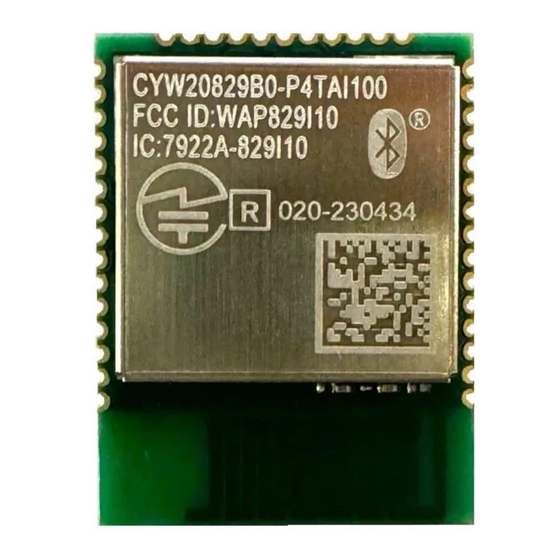
The Original Equipment Manufacturer (OEM) must ensure that FCC labeling requirements are met. This includes a clearly visible label on the outside of the OEM enclosure specifying the appropriate Infineon FCC identifier for this product as well as the FCC Notice above. The FCC identifier is FCC ID: WAP829I10. -
Page 68: Ised
AIROC™ Bluetooth® LE module Regulatory information RF EXPOSURE: To comply with FCC RF Exposure requirements, the Original Equipment Manufacturer (OEM) must ensure to install the approved antenna in the previous. The preceding statement must be included as a CAUTION statement in manuals, for products operating with the approved antenna in Table 7, to alert users on FCC RF Exposure compliance. -
Page 69: European Declaration Of Conformity
The Original Equipment Manufacturer (OEM) must ensure that ISED labeling requirements are met. This includes a clearly visible label on the outside of the OEM enclosure specifying the appropriate Infineon IC identifier for this product as well as the ISED Notices above. The IC identifier is 7922A-829I10. In any case, the end product must be labeled in its exterior with “Contains IC: 7922A-829I10”... -
Page 70: Mic Japan
AIROC™ Bluetooth® LE module Regulatory information 10.4 MIC Japan CYW20829B0-P4TAI100 is certified as a module with certification number 020-230434. End products that integrate CYW20829B0-P4TAI100 do not need additional MIC Japan certification for the end product. End product can display the certification label of the embedded module. Figure 11 MIC label Datasheet... -
Page 71: Packaging
AIROC™ Bluetooth® LE module Packaging Packaging Table 44 Solder Reflow peak temperature Maximum peak Maximum time at peak Module part number Package No. of cycles temperature temperature CYW20829B0-P4TAI100 41-pad SMT 260°C 30 seconds CYW20829B0-P4EPI100 41-pad SMT 260°C 30 seconds Table 45 Package Moisture Sensitivity Level (MSL), IPC/JEDEC J-STD-2 Module part number Package... - Page 72 AIROC™ Bluetooth® LE module Packaging Figure 14 details reel dimensions used for the CYW20829B0-P4TAI100. Figure 14 Reel dimensions Datasheet 002-39262 Rev. ** 2024-01-23...
-
Page 73: Ordering Information
The CYW20829B0-P4TAI100 is offered in tape and reel packaging. The CYW20829B0-P4TAI100 ships in a reel size of 500. For additional information and a complete list of Infineon Wireless products, contact your local Infineon sales representative. To locate the nearest Infineon office, visit our website. -
Page 74: Acronyms
AIROC™ Bluetooth® LE module Acronyms Acronyms Table 48 Acronyms used in this document Acronym Description analog-to-digital converter advertising arithmetic logic unit AMUXBUS analog multiplexer bus application programming interface Arm® advanced RISC machine, a CPU architecture Bluetooth® Low Energy Bluetooth® SIG Bluetooth®... - Page 75 AIROC™ Bluetooth® LE module Acronyms Table 48 Acronyms used in this document (continued) Acronym Description infinite impulse response, see also FIR internal low-speed oscillator, see also IMO internal main oscillator, see also ILO integral nonlinearity, see also DNL IPOR initial power-on reset IPSR interrupt program status register interrupt request...
- Page 76 AIROC™ Bluetooth® LE module Acronyms Table 48 Acronyms used in this document (continued) Acronym Description PRES precise power-on reset pseudo random sequence port read data register PSoC® Programmable System-on-Chip™ PSRR power supply rejection ratio pulse-width modulator QDID qualification design ID random-access memory RISC reduced-instruction-set computing...
- Page 77 AIROC™ Bluetooth® LE module Acronyms Table 48 Acronyms used in this document (continued) Acronym Description UART Universal Asynchronous Transmitter Receiver, a communications protocol universal digital block Universal Serial Bus USBIO USB input/output, PSoC pins used to connect to a USB port VDAC voltage DAC, see also DAC, IDAC watchdog timer...
-
Page 78: Document Conventions
AIROC™ Bluetooth® LE module Document conventions Document conventions 14.1 Units of measure Table 49 Units of measure Symbol Unit of measure °C degrees Celsius decibel decibel-milliwatts femtofarads hertz 1024 bytes kbps kilobits per second kilohour kilohertz k kilo ohm ksps kilosamples per second least significant bit Mbps... -
Page 79: Revision History
AIROC™ Bluetooth® LE module Revision history Revision histor y Document Date of release Description of changes version 2024-01-23 Initial release. Datasheet 002-39262 Rev. ** 2024-01-23... - Page 80 For information on the types Published by characteristics (“Beschaffenheitsgarantie”). in question please contact your nearest Infineon Technologies office. With respect to any examples, hints or any typical Infineon Technologies AG...
Need help?
Do you have a question about the AIROC CYW20829B0-P4TAI100 and is the answer not in the manual?
Questions and answers