Air Lift WirelessONE 25870 Installation Manual
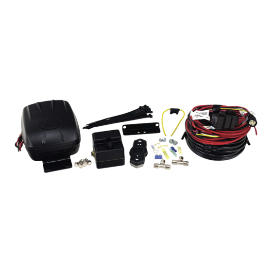
Key fob activated compressor system
Hide thumbs
Also See for WirelessONE 25870:
- User manual (24 pages) ,
- Installation manual (20 pages) ,
- Installation manual (15 pages)
Table of Contents
Advertisement
Quick Links
Advertisement
Table of Contents

Related Manuals for Air Lift WirelessONE 25870


Summary of Contents for Air Lift WirelessONE 25870
- Page 1 Kit 25870 WirelessONE Key Fob Activated Compressor System INSTALLATION GUIDE For maximum effectiveness and safety, please read these instructions completely before proceeding with installation. Failure to read these instructions can result in an incorrect installation.
-
Page 3: Table Of Contents
TABLE OF CONTENTS Introduction . . . . . . . . . . . . . . . . . . . . . . . . . . . . . . . . . . . . . . . . . . . 2 System Information . -
Page 4: Introduction
Air Lift Company reserves the right to make changes and improvements to its products and publications at any time. Contact Air Lift Company at (800) 248-0892 for the latest version of this manual. -
Page 5: Installation Schematics
WirelessONE Installation - Electrical Schematic fig. 1 MN-751... -
Page 6: Pneumatic Schematic
WirelessONE Installation - Pneumatic Schematic Schrader Valve fig. 2 MN-751... -
Page 7: Hardware & Tool Lists
24681 3/8” Ring Terminal ......1 24595 Female spade, 12 ga ......1 Missing or damaged parts? Call Air Lift customer STOP! service at (800) 248-0892 for a replacement part. TOOLS LIST Description ..........Qty Description . -
Page 8: Installing The Wirelessone System
WirelessONE Installing the WirelessONE System RECOMMENDED COMPRESSOR LOCATIONS Important LOCATE COMPRESSOR IN DRY, PROTECTED AREA ON VEHICLE. DIRECT SPLASH OR EXCESSIVE MOISTURE CAN DAMAGE THE COMPRESSOR AND CAUSE SYSTEM FAILURE. Disclaimer: If you choose to mount the compressor outside the vehicle please keep in mind the compressor body must be shielded from direct splash. -
Page 9: Installing The Manifold
WirelessONE INSTALLING THE MANIFOLD IF THE USER INSTALLS THE MANIFOLD OR COMPRESSOR IN THE CAB OF THE WARNING VEHICLE IN EXTREME WEATHER CLIMATES, DO NOT USE ANY ANTI-FREEZE PRODUCT IN THE SYSTEM AS EXHAUST FUMES CAN BE TOXIC. CARE MUST BE TAKEN WHEN USING THIS PRODUCT! IT IS RECOMMENDED THAT THIS PRODUCT’S MSDS SHEET BE REVIEWED BEFORE USE! THIS CAN BE OBTAINED WHERE YOU PURCHASED THIS PRODUCT. -
Page 10: Attaching The Air Lines
WirelessONE 1. Connect electrical connector to manifold (B). a. Push down till fully seated. b. Push red secondary lock down. 2. Connect compressor to harness. a. Cut off terminal on compressor red wire. b. Strip 1/4” insulation off compressor red wire. c. -
Page 11: How To Remove And Install The Batteries In The Remote Contrtol Unit
WirelessONE “T-Fitting” to Springs: 1. Cut a section of the 1/4” DOT air line (D) provided to go from “T-Fitting” (F) to Left and Right air springs. 2. Insert one side of air line (D) into “T-Fitting” (F) and the other into the air springs. HOW TO REMOVE AND INSTALL THE BATTERIES IN THE REMOTE CONTROL UNIT 1. -
Page 12: Operational Modes
WirelessONE OPERATIONAL MODES Normal Mode : Mode in which the user can increase and decrease to the desired pressure, as well as set and recall the three memory pressures. “LB” will be displayed on startup when the battery is getting low. Settings Mode: Mode in which the user can change the backlighting color, alter the unit of measure (PSI, or BAR). -
Page 13: Saving And Recalling Memory 1
WirelessONE Saving and Recalling Memory 1: Recalling Memory • Initial press of any button will wake up display and not perform any function. • Upon wake up the LCD will display the Desired pressure. • Press the M1 button to set the M1 pressure as the desired pressure. •... -
Page 14: How To Sync The Receiver To The Transmitter
WirelessONE HOW TO SYNC THE RECEIVER TO THE TRANSMITTER (ONLY NEEDED WITH A REPLACEMENT TRANSMITTER) 1. Turn ignition on. 2. Locate the sync wire in the wire harness. • It will be the yellow wire that is looped with a yellow cap around it. 3. -
Page 15: Warranty And Returns Policy
Seller disclaims the implied warranty of merchantability. (Dated proof of purchase required.) Air Lift 1000™ ....Lifetime Limited LoadController/Dual™ ..2 Year Limited RideControl™... -
Page 16: Replacement Information
WirelessONE Replacement Information If you need replacement parts, contact the local dealer or call Air Lift customer service at (800) 248-0892. Most parts are immediately available and can be shipped the same day. Contact Air Lift Company customer service at (800) 248-0892 first if: •... -
Page 17: Important:avoiding Cold Weather Freeze-Up
WirelessONE IMPORTANT: To Avoid Cold Weather Freeze-up Important To avoid COLD WEATHER FREEZE UP: Add 4 oz . (1/2 cup) of “GUNK” Brand AIR BRAKE ANTI FREEZE Directly into each flex member. Remove the air line and/or fitting from the air bag and fill directly. Gunk Brand Air Brake Anti-Freeze may be purchased at an automotive parts store or truck supply store. -
Page 18: Templates
WirelessONE Templates MN-751... - Page 19 WirelessONE Notes MN-751...
- Page 20 Thank you for purchasing Air Lift products — the professional installer’s choice! Air Lift Company • 2727 Snow Road • Lansing, MI 48917 or PO Box 80167 • Lansing, MI 48908-0167 Toll Free (800) 248-0892 • Local (517) 322-2144 • Fax (517) 322-0240 • www.airliftcompany.com...
Need help?
Do you have a question about the WirelessONE 25870 and is the answer not in the manual?
Questions and answers