Advertisement
- 1 Introduction
- 2 Wireless Controller
- 3 Mobile App Pairing
- 4 Mobile App User Interface
- 5 Mobile App Configuration
-
6
Troubleshooting
- 6.1 The unit doesn't run when inflation is commanded
- 6.2 System does not exhaust when deflation is commanded
- 6.3 Nothing happens when the vehicle is turned on
- 6.4 Nothing happens when making an adjustment with the remote
- 6.5 Unable to connect to the manifold with the remote
- 6.6 System does not maintain/reach ride height
- 6.7 The unit runs often without commanding an inflate adjustment
- 7 Replacing Batteries in the Wireless Controller
- 8 Finding Air Leaks
- 9 Fixing Leaks on Barbed Fittings
- 10 Cutting Air Lines
- 11 Fixing Leaks on PTC Fittings
- 12 Replacement Part Information
- 13 Contact Information
- 14 Documents / Resources
Introduction
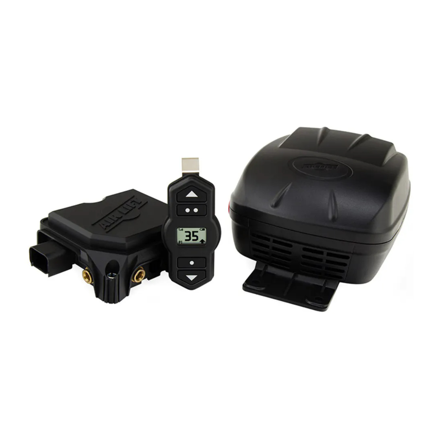
WirelessOne is an on-board air compressor system designed to easily level the vehicle digitally. It can be operated both with the included wireless controller and with a free app, available for iOS and Android operating systems.
The kit includes a compressor, manifold, wiring harness, wireless digital controller, air line and integrating hardware. The system can be used inside or outside the vehicle for adjustments in full view of the vehicle.
The wireless digital controller is a compact, battery-powered unit. Three user-defined memory settings are provided for frequently used settings. As an added safety measure, WirelessOne maintains minimum air pressure of 5 PSI (.34BAR) in the system. The manifold is also weather resistant for maximum life expectancy.

WHEN SETTING UP USING A TANK AND EXTERNAL SOLENOID, CONSIDERED INDIRECT COMPRESSOR FILL, TANK MODE MUST BE SELECTED IN SETTINGS. SIMILARLY, USING A DIRECT COMPRESSOR FILL SETUP (IE. THE COMPRESSOR FILLS THE AIR SPRINGS DIRECTLY) REQUIRES COMPRESSOR MODE TO BE SELECTED IN SETTINGS. USING EITHER MODE IN THE WRONG SETUP WILL LEAD TO SYSTEM ERRORS AND POOR PERFORMANCE.
NOTATION EXPLANATION
Hazard notations appear in various locations in this publication. Information which is highlighted by one of these notations must be observed to help minimize risk of personal injury or possible improper installation, which may render the vehicle unsafe. Notes are used to help emphasize areas of procedural importance and provide helpful suggestions. The following definitions explain the use of these notations as they appear throughout this guide.

INDICATES IMMEDIATE HAZARDS WHICH WILL RESULT IN SEVERE PERSONAL INJURY OR DEATH.

INDICATES HAZARDS OR UNSAFE PRACTICES WHICH COULD RESULT IN SEVERE PERSONAL INJURY OR DEATH.
INDICATES HAZARDS OR UNSAFE PRACTICES WHICH COULD RESULT IN DAMAGE TO THE MACHINE OR MINOR PERSONAL INJURY.
Wireless Controller

Fig. B.1
OPERATION
- Push any button to wake up the controller, which will show the desired pressure.
- Press the up or down arrows to raise or lower the pressure in increments of 1 PSI or 0.1BAR.
- Maximum pressure is 100 PSI (7BAR)*.


*Maximum pressure varies. See chart in section "Mobile App User Interface".
BACKLIGHT
The controller display stays on for 40 seconds. The backlight automatically dims after 2 to 10 seconds, depending on battery condition, then goes off after an additional 30 seconds. Press any button to wake up the controller.
NOTE
To enter the menu, press and hold the center button for 5 seconds (Fig. B.1).
NOTE
Tank mode can only be enabled or disabled through the mobile app.
PAIR THE MANIFOLD TO THE WIRELESS CONTROLLER
The manifold will enter pairing mode for three minutes after the fuse is installed.
Once a device is paired, it will automatically connect if no other device is already connected. The wireless controller will go into sleep mode after 40 seconds, at which time it will disconnect from the system.
NOTE
The wireless controller comes with batteries installed. To operate the device, slowly pull the tab out of the battery compartment.
- To initiate pairing mode, remove the fuse, wait five seconds and reinstall.
- Press any button to wake up the controller. It will automatically go to the pairing screen if it is not already paired with a manifold. Use the up and down arrow buttons to navigate the pairing menu. Select the device that matches the manifold serial number (Figs. B.2 & B.3).
![]()
- Use the up and down arrows to choose the manifold. Press
![]() (P1) to begin the pairing process.
(P1) to begin the pairing process. - The device will indicate "pairing" when it is connecting to a device. There is no Bluetooth password.
- Once complete, the controller will either indicate "Pairing successful," which means the devices are paired or "Pairing unsuccessful," which will require the user to pull and reinstall the fuse and try again. Once the wireless controller is connected to the manifold, it will automatically connect each time the manifold is active and the controller is woken up.

 (P1) to begin the pairing process.
NOTE To enter the menu, press the inflate and deflate buttons simultaneously (Fig. B.1).
UNITS

Choose Units from the menu to change between PSI and BAR (Fig. B.4). The factory default is PSI.
TROUBLESHOOT
Choose Troubleshoot from the menu to see system error messages. For more information about error messages, see Troubleshooting.
WIRELESS CONTROLLER PRESETS
- Set the pressure to the desired level using the inflate and deflate buttons (Fig. B.5).

- To set each preset:
Preset 1: Press and hold the • (P1) for 3 seconds.
Preset 2: Press and hold •• (P2) for 3 seconds.
Preset 3: Push and hold the • and •• buttons simultaneously for 3 seconds. - For example, after setting the desired pressure, press and hold the • to set preset 1.
- The controller will indicate which preset is currently selected in the lower left corner.

Mobile App Pairing
- Download the free Air Lift WirelessOne app from the Apple App Store for iOS. Search for Air Lift WirelessOne.


- Put the manifold in pairing mode by removing the fuse and reinstalling it after five seconds. The manifold will remain in pairing mode for three minutes after the fuse is reinserted.
- The app will automatically go to the device's screen if no connected manifold is detected. Click on the device you want to pair. The manifold will have WirelessOne in the title (Fig. C.1 & Fig. C.2).

- Once the mobile app is paired to the manifold via Bluetooth, it will connect automatically each time the manifold is active and the device is in range. Only one device can be connected at a time. To connect another device, the app on any device currently connected must be closed.
- To pair a second mobile device, repeat the procedure on that device. The manifold can pair with up to 10 mobile devices. There is no limit to the number of manifolds one mobile device can pair with.

NOTE
The app cannot pair to the manifold if it is currently paired to a hand-held remote that is on.
Mobile App User Interface
- When the app is open to the user interface, it shows the desired pressure (Fig. D.1 & Fig. D.2).

- Press the up or down arrows to inflate or deflate in increments of 1 PSI (0.1BAR).
- Click on the gear for each preset to set and name the presets.
- Click on the air pressure number to manually enter a desired pressure.

| Air Spring System | Minimum Pressure | Maximum Pressure | ||
| PSI | BAR | PSI | BAR | |
| Air Lift 1000 | 5 | .34 | 35 | .4 |
| Air Lift 1000HD | 5 | .34 | 50 | .4 |
| RideControl | 5 | .34 | 100 | 7 |
| LoadLifter Series | 5 | .34 | 100 | 7 |
Mobile App Configuration
SETTINGS
The Main Settings screen (Fig. E.1 & Fig. E.2) has these options:

NOTE
Settings are enabled when the check is next to the option.
Devices
- Lists manifolds that are within range
Troubleshoot
- Displays system error messages (See F. Troubleshooting)
- Allows user to send pre-configured diagnostic email to Customer service for troubleshooting assistance
Settings
- Pressure control units (PSI or BAR)
- Compressor/Tank Settings - Compressor is the default setup. Select Tank if you are using an auxiliary tank and external solenoid to supply the manifold
NOTE
Tank mode can only be enabled or disabled through the mobile app.
- Prevent Screen Lock stops the mobile device screen from going to sleep while the app is open
Firmware Update
Communicate
Online Help
- Links to AirLiftCompany.com

About (Fig. E.3 & Fig. E.4)
- Shows the app software revision and manifold firmware revision
Use the arrow in the upper left corner to go back to the User interface.
APP PRESETS
- The app must be connected to the manifold to change presets (Fig. E.5 & Fig. E.6). Presets are stored on the manifold, so changes made in the app will also affect the wireless controller and vice versa.

- Adjust presets by clicking on the gear next to each preset.
- To adjust preset values, click on the name or pressure value and type the desired name and pressure.
- Click "Accept" to save the preset or "Cancel" to close the preset screen.

FIRMWARE UPDATES
- The phone must be connected to the internet and the app must be connected to the manifold to change firmware on the manifold (Fig. E. 7 & Fig. E.8).

- Press start to begin the update process. A secondary confirmation will appear.
- Press "OK" from the secondary confirmation pop-up and the update will begin (Fig. E.9 & Fig. E.10).

- DO NOT close the app or turn the manifold off during this process.


Troubleshooting
For any code not listed, contact Air Lift Customer Service at (800) 248-0892 or service@airliftcompany.com.
Error codes are labeled "Active Errors" and "Dormant Errors" on the app (Fig. F.1 & Fig. F.2). Active and dormant error codes are indicated by "A" and "D" on the wireless controller (Fig. F.3).
Use the "CLEAR ERRORS" button to clear current codes and check for presently active codes.

Examples of error codes on the smartphone apps for iOS and Android

Example of an error code on the wireless controller
NOTE
Error codes can only be cleared by using the mobile app.
TROUBLESHOOTING GUIDE
| Problem | Error Code | Potential Cause | Solution |
| If the ignition wire is not connected, the system will only maintain a preset when the vehicle starts moving or is connected to the wireless controller or mobile app. | |||
The unit doesn't run when inflation is commanded | 1 | Vehicle battery voltage is too low (below 9 volts) | Check the vehicle battery |
| 2 | Vehicle battery voltage is too high (above 18 volts) | Check the vehicle battery and charging system | |
| 3 | Manifold temperature is too cold | Allow manifold to warm up | |
| 4 | Manifold temperature is too hot | Allow manifold to cool down. Move manifold to location that is not near heat sources | |
| 14 | Compressor under-current | Check battery and ground connections. Disconnect the compressor and test on the bench using 12 volts. Remove and reinstall the 15A fuse to reset the fault. | |
| 15 | Compressor over-current | Use the mobile app to clear the error code. Disconnect the compressor and test on the bench using 12 volts | |
| 18 | Compressor duty cycle limit has been reached | Allow the compressor to sit idle until the cool down period (15 minutes) has been reached | |
| 19 | Blockage in the compressor or system which is preventing air flow | Check for system blockages or frozen moisture in the air lines. Remove and reinstall the 15A fuse to reset the fault | |
| - | Bad ground, poor wire connections, bad compressor or bad manifold | Disconnect the compressor and test on the bench using w12 volts | |
System does not exhaust when deflation is commanded | 1 | Vehicle battery voltage is too low (below 9 volts) | Check the vehicle battery |
| 2 | Vehicle battery voltage is too high (above 18 volts) | Check the vehicle battery and charging system | |
| 3 | Manifold temperature is too cold | Allow manifold to warm up | |
| 4 | Manifold temperature is too hot | Allow manifold to cool down. Move manifold to location that is not near heat sources | |
Nothing happens when the vehicle is turned on | - | If the ignition wire is not connected, the system will only maintain a preset if the vehicle starts moving or is connected to the wireless controller or mobile app | Connect the optional ignition wire if desired. Connect to the manifold using the remote or mobile app to wake the system up for quicker adjustments |
Nothing happens when making an adjustment with the remote | - | When first powering on the wireless controller, the Bluetooth connection is established in the background. Changes to the desired pressure can be made while connecting, but the adjustment command won't be sent until the Bluetooth connection is complete and signal strength icon is visible in the upper left corner of the screen | Wait for the Bluetooth connection to complete. The last adjustment will automatically be made once the connection is established |
Unable to connect to the manifold with the remote | - | Wireless controller batteries are low | Check wireless controller battery icon. Change batteries if necessary |
| - | Blown 15A fuse | Check 15A fuse. Enter the pairing screen on the remote or the devices menu on the mobile app and see if the manifold is visible via Bluetooth | |
| - | Weak Bluetooth signal | Ensure the manifold is mounted forward of the rear axle. Move manifold to a location that is not shielded by metal | |
| - | Wireless controller has become unpaired from the manifold | Re-pair the remote by removing and re-inserting the 15A fuse. The manifold will be in pairing mode for 3 minutes after power is applied | |
System does not maintain/reach ride height | 21 | Large leak in the system | Locate and correct leak (See Finding Air Leaks and Fixing Leaks on Barbed Fittings and Fixing Leaks on PTC Fittings). Remove and reinstall the 15A fuse to reset the fault |
| - | The vehicle could be overloaded | If the air pressure in the system is at its max pressure of 100 PSI (7BAR), the system will stop inflating. | |
| - | Compressor mode is enabled in a tank setup | Put the system in tank mode via settings in the app | |
The unit runs often without commanding an inflate adjustment | 22 | Small air leak in the system | Locate and correct leak (See Finding Air Leaks and Fixing Leaks on Barbed Fittings and Fixing Leaks on PTC Fittings) |
| Compressor turns on when commanding fill, but does not hit pressure target | 15 | The system is set to tank mode in a compressor setup | Put the system in compressor mode via settings in the app |
Replacing Batteries in the Wireless Controller

- To install the two CR2032 batteries in the wireless controller, use a small flat screwdriver to separate the two halves of the controller by prying apart the internal clip locations.
- Stack the batteries positive to negative inside the rear cover with the positive end pointed in the direction of the circuit board. Take note of "NEG" on the case and "+" symbol on the circuit board.
- Snap the front cover/circuit board onto the rear cover.
Finding Air Leaks
- Inflate the air springs to 30 PSI (2.1BAR).
- Spray all connections with a solution of liquid dish soap and water. Wait 30 seconds and check for bubbles which indicate leaks.
![]()
- Check the air pressure again after 24 hours. A 2-4 PSI (.14-.28BAR) loss after initial installation is normal. Retest for leaks if the loss exceeds 5 PSI (.34BAR).
- After checking for leaks, deflate the springs to the minimum pressure required to restore the system to normal ride height.

Fixing Leaks on Barbed Fittings
- If there is a leak at the Schrader valve, tighten the valve with a valve core tool.
- If there is a leak at any barbed fitting, cut the air line 1 1/2" (38mm) behind the fitting. Use a pair of pliers or locking pliers to twist and pull the air line off of the fitting. Do not cut the air line lengthwise at the fitting because this could nick the barbs, likely causing it to leak.
![]()
- Reinstall the air line and the air line clamp if the fitting has one. Make sure the air line covers all barbs.

Cutting Air Lines
When cutting air lines, use a sharp knife or a hose cutter and make clean, square cuts. Do not use scissors or wire cutters because these tools will deform the air line, causing it to leak around fittings. Do not cut the lines at an angle.
The maximum bend radius for 1/4" air line is 1" (25mm). Do not bend the air line more than the maximum bend radius or side load the fitting connections. Air lines are to be installed straight into fittings.
Fixing Leaks on PTC Fittings
After insertion, check the PTC fitting connection by pulling on each line to verify a robust connection.

To release the air line from the connection, first release all air from the system. Push in on the air line (step 1), push the collar in (step 2), and with the collar depressed, pull the air line out of the fitting (step 3).
To reconnect, push the air line into the fitting and pull to verify a robust connection.
TIPS
- To ensure a proper seal, cut off the end of the air line just beyond the witness mark before reinstalling in the fitting.
- If the fitting is leaking at the threads, it may be necessary to remove and re-apply thread sealant on the threads and re-install 1 1/2 turns beyond finger tight.
Replacement Part Information
If replacement parts are needed, contact the local dealer or call Air Lift customer service at (800) 248-0892. Most parts are immediately available and can be shipped the same day.
- To register your warranty, please visit https://www.airliftcompany.com/support/warranty/register/
Contact Air Lift Company customer service at (800) 248-0892 first if:
- Parts are missing from the kit.
- Need technical assistance on installation or operation.
- Broken or defective parts in the kit.
- Wrong parts in the kit.
- Have a warranty claim or question.
Contact the retailer where the kit was purchased:
- If it is necessary to return or exchange the kit for any reason.
- If there is a problem with shipping if shipped from the retailer.
- If there is a problem with the price.
Contact Information
| Mailing address | P.O. Box 80167 Lansing, MI 48908-0167 |
| Shipping addressfor returns | 2727 Snow Road Lansing, MI 48917 |
| Phone | Toll free: (800) 248-0892 International: +1 (517) 322-2144 |
| service@airliftcompany.com | |
| Web address | www.airliftcompany.com |
Need Help?
Contact Customer Service at: (800) 248-0892 or email: service@airliftcompany.com
For calls outside the U.S. or Canada: (517) 322-2144
Air Lift Company 2727 Snow Road Lansing, MI 48917
California:
Cancer and Reproductive Harm – www.P65Warnings.ca.gov
Documents / Resources
References
Air Lift Warranty Registration | Air Lift Company
Air Lift® Air Springs
![www.p65warnings.ca.gov]() http://www.p65warnings.ca.gov
http://www.p65warnings.ca.gov![www.apple.com]() App Store - Apple
App Store - Apple![play.google.com]() Google Play
Google PlayAir Lift® Air Springs

Download manual
Here you can download full pdf version of manual, it may contain additional safety instructions, warranty information, FCC rules, etc.
Advertisement


Need help?
Do you have a question about the WirelessOne and is the answer not in the manual?
Questions and answers