Table of Contents
Advertisement
Quick Links
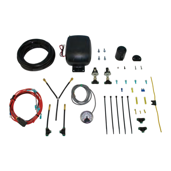
Kits 25852
LoadCONTROLLER
/ Dual
™
and 25856
Dual Gauge Analog
Compressor Systems
Kit #25852 with standard duty compressor
Kit #25856 with heavy duty compressor
INSTALLATION GUIDE
For maximum effectiveness and safety,
please read these instructions completely
before proceeding with installation.
Failure to read these instructions can result in an
incorrect installation.
Advertisement
Table of Contents


Need help?
Do you have a question about the LoadCONTROLLER/Dual 25852 and is the answer not in the manual?
Questions and answers