Table of Contents
Advertisement
Quick Links
Advertisement
Table of Contents

Subscribe to Our Youtube Channel
Related Manuals for Advantech MIC-3365


Summary of Contents for Advantech MIC-3365
- Page 1 MIC-3365 CompactPCI™...
-
Page 2: Copyright Notice
All other product names or trademarks are properties of their respective owners. CE Notification The MIC-3365, developed by Advantech CO., LTD., has passed the CE test for environment specification when shielded cables are used for external wiring. We recommend the use of shielded cables. - Page 3 MIC-3365 User's Manual...
-
Page 4: Product Warranty
Because of Advantech’s high quality-control standards and rigorous testing, most of our customers never need to use our repair service. If an Advantech product is defective, it will be repaired or replaced at no charge during the warranty period. For out-of-warranty repairs, you will be billed according to the cost of replacement materials, service time and freight. -
Page 5: Packing List
If any of these items are missing or damaged, contact your distributor or sales representative immediately. Technical Support and Sales Assistance If you have any technical questions about the MIC-3365 or any other Advantech products, please visit our support website at: • http://www.advantech.com.tw/support... -
Page 6: Table Of Contents
1.2 Specifications ................... 3 1.2.1 Standard SBC functions ................ 3 1.2.2 VGA interface ..................4 1.2.3 Ultra 2 SCSI Interface (MIC-3365 and MIC-3365F) ......4 1.2.4 Mechanical and environmental specifications ........4 1.3 Function Block Diagram ..............5 1.4 Board Dimensions ................6 1.5 Jumpers .................... - Page 7 A.1 VGA Display Connector (CN2) ............. 74 A.2 Keyboard and Mouse Connnector (CN7) ........74 A.3 COM1 and COM2 Serial Port (CN13 and CN6) ......75 A.4 USB Connector (CN8) ..............76 A.5 Ethernet RJ-45 Connector (CN4 and CN5) ........76 MIC-3365 User's Manual...
- Page 8 A.6 Parallel Port Connector (CN1) ............. 77 A.7 IDE Connector (CN12) ..............78 A.8 Floppy Drive Connnector (CN11) ..........79 A.9 System I/O Ports ................80 A.10 DMA Channel Assignments ............81 A.11 Interrupt Assignments ..............81 A.12 1st MB Memory Map ..............82 A.13 J1 connector pin assignments ............
- Page 9 Tables MIC-3365 User's Manual...
- Page 10 Preface and Table of Contents...
- Page 11 Figures MIC-3365 User's Manual...
-
Page 12: Hardware Configuration
Hardware Configuration... -
Page 13: Introduction
1-slot MIC-3365F 2-slot Please check which version of the MIC-3365 you have on hand. Some of the functions in this manual may not be applicable to some versions. The MIC-3365 supports rear transition board and is best performed with the MIC-3302. Please refer to the MIC-3302's manual for more detailed information. -
Page 14: Specifications
• Parallel port: Configured to LPT1, LPT2, LPT3 or disabled. Supports multi-mode parallel port (SPP/ECP/EPP) • Serial ports: Two RS-232 ports with 16C550 UARTs. MIC-3365 and MIC-3365D provides one serial port, and MIC-3365F provides two serial ports on the front panel ®... -
Page 15: Vga Interface
80 MB/s • Available on the rear transition board (MIC-3302) via J5 connector 1.2.4 Mechanical and environmental specifications • Board size: 233.35 x 160 mm (6U size), MIC-3365 and MIC-3365D is 1-slot (4TE) wide, and MIC-3365F is 2-slot (8TE) wide ®... -
Page 16: Function Block Diagram
Function Block Diagram Figure 1-1: MIC-3365 function block diagram Chapter 1 Hardware Configuration... -
Page 17: Board Dimensions
Board Dimensions 160 mm 233.35 mm Figure 1-2: MIC-3365 board dimensions MIC-3365 User's Manual... -
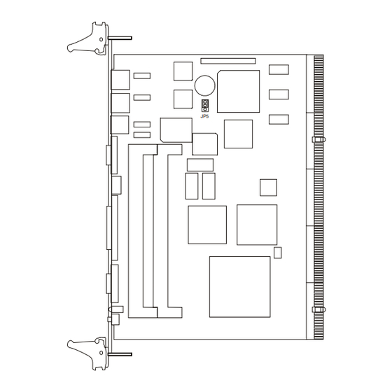
Page 18: Jumpers
Jumpers 1.5.1 Jumper Locations The MIC-3365 provides jumpers for configuring your board for specific applications other than the default settings. Table 1-1 list the jumper functions. Figure 1-3 illustrates the jumper locations. The default jumper setting is illustrated in Figure 1-3. -
Page 19: Jumper Settings
You may find a pair of needle-nose pliers useful for setting the jumpers. If you have any doubts about the best hardware configuration for your application, contact your local distributor or sales representative before you make any changes. MIC-3365 User's Manual... -
Page 20: Clear Cmos (Jp5)
1.5.3 Clear CMOS (JP5) This jumper is used to erase CMOS data and reset system BIOS information. Follow the procedures below to clear the CMOS. 1. Turn off the system. 2. Close jumper JP5 (2-3). 3. Turn on the system. The CMOS is now cleared. 4. -
Page 21: Connectors
Table 1-3 lists the function of each connector and Figure 1-4 and Figure 1-5 illustrate each connector location. Chapter 2 gives instructions for connecting external devices to your card. Number Function Please refer to Appendix A for pin assignments. MIC-3365 User's Manual... - Page 22 Figure 1-4: MIC-3365 connector locations Chapter 1 Hardware Configuration...
-
Page 23: Front Panel Connectors And Indicators
Front Panel Connectors and Indicators LAN1 LAN2 COM1 COM1 COM1 COM2 PRINTER RESET RESET RESET Figure 1-5: MIC-3365 front panel connector and indicator locations MIC-3365 User's Manual... -
Page 24: Safety Precautions
• Random vibration: 1.5 Grms Safety Precautions Follow these simple precautions to protect yourself from harm and the products from damage. 1. To avoid electrical shock, always disconnect the power from your PC chassis before you work on it. Don't touch any components on the CPU card or other cards while the PC is on. -
Page 25: Installing Sdram (Dimms)
DIMMs of any size, giving a total memory capacity between 16 and 512 MB. Since the MIC-3365 can operate at 66 or 100 MHz, we recommend using PC100-compliant DIMMs. The procedure for installing DIMMs appears below. Please follow these steps carefully. -
Page 26: Installing Cpu Heat Sink And Hdd, Fdd Brackets
CPU. In order to meet critical environmental conditions and the physical space of the MIC-3365 at the same time, Advantech designed a heat sink to fulfill both needs. Please refer to Figure 1-7 for an illustration of the heat sink used for the MIC-3365 and MIC-3365D, 1-slot wide solution. - Page 27 Figure 1-7: Heat sink installation for 2U solution MIC-3365 User's Manual...
-
Page 28: Software Support
1.11 Software Support The MIC-3365 supports lots of operating systems, such as Microsoft Windows family, Linux, SCO UNIX, QNX, etc. NOTE: At the beginning of QNX installation process, please follow the system's installation guide shown on the screen. Press anykey and F2 when asked, and then choose VGA 16 Color Only, and press <space>... - Page 29 MIC-3365 User's Manual...
-
Page 30: Connecting Peripherals
Connecting Peripherals... -
Page 31: Ide Device (Cn12)
The MIC-3365 provides two IDE (Integrated Device Electronics) channels via the J3 connector to the rear transition board MIC-3302. Four IDE drives can be connected to the MIC-3365 through the rear transition board MIC-3302. The MIC-3365F provides a mounting bracket to mount a 2.5" hard disk drive on board. -
Page 32: Vga Display Connector (Cn2)
The MIC-3365 provides a 6-pin mini-DIN connector (CN7) on the front panel for connection of PS/2 keyboard and PS/2 mouse. The MIC-3365 comes with a cable to convert from the single 6-pin mini- DIN connector to a double PS/2 keyboard connector and PS/2 mouse connector. -
Page 33: Ethernet Configuration (Cn4 And Cn5)
Address Default Ethernet Configuration (CN4 and CN5) The MIC-3365 is equipped with dual high performance 32-bit PCI- bus Fast Ethernet interfaces which are fully compliant with IEEE 802.3u 10/100Base-TX specifications. It is supported by all major network operating systems and is 100% Novell NE-2000 compatible. -
Page 34: Ultra 2 Scsi Interface
Ultra 2 SCSI Interface The MIC-3365 and MIC-3365F provides an Ultra 2 SCSI interface on the rear transition board MIC-3302 via the J5 connector. The MIC-3302 has a 68-pin, dual in-line connector for Ultra 2 SCSI devices. Connection of SCSI devices requires special attention, especially when determining the last drive on the SCSI chain. - Page 35 2. Lift the upper handle up and press the lower handle down to release the card from the backplane. 3. Slide the card out. Keep your fingers away from this area. Figure 2-1: Installing the card into the chassis MIC-3365 User's Manual...
-
Page 36: Ethernet Software Configuration
Ethernet Software Configuration... -
Page 37: Introduction
Also includes AFT. This function requires a Cisco switch with FEC capability. The MIC-3365 comes with drivers for a wide variety of networks and operating systems. The MIC-3365 is an excellent choice for operation in standalone and harsh industrial environments. - Page 38 Microsoft Windows • \MIC3365\LAN\E100BNT.SYS (NDIS 4.0), \MIC3365\LAN\ OEMSETUP.INF: Drivers for Windows NT 4.0 • \MIC3365\LAN\E100B.SYS (NDIS 3), \MIC3365\LAN\ OEMSETUP.INF: Drivers for Windows NT 3.51 • \MIC3365\LAN\NET82557.INF: Drivers for Windows 98 • \MIC3365\LAN\E100BNT.SYS (NDIS 4.0), \MIC3365\LAN\ NET82557.INF: Drivers for Windows 95 •...
- Page 39 98/NT Add New Hardware wizard. Choose the driver from the utility CD-ROM disc. Note: Operating system vendors may post driver updates on their web sites. Please visit the web sites of OS vendors to download updated drivers. MIC-3365 User's Manual...
-
Page 40: Installation For Windows Nt 4.0
3.3 Installation for Windows NT 4.0 1. In the Windows NT screen, select "Start", click "Settings". Click the "Control Panel" item and choose "Network". 2. Click "Yes". Chapter 3 Ethernet Software Configuration... - Page 41 3. Click "Wired to the Network", or users may choose "Remote access to the network" if applicable. 4. Click "Select from list". MIC-3365 User's Manual...
- Page 42 5. Click "Have Disk". 6. Type in "E:\MIC3365\LAN" in the blank column and click "OK". Chapter 3 Ethernet Software Configuration...
- Page 43 7. Click "OK". 8. Click "Next". MIC-3365 User's Manual...
- Page 44 9. Click "Next". 10. Click "Next". Chapter 3 Ethernet Software Configuration...
- Page 45 11. Click "Next". 12. Insert Windows NT source disc in drive E. Type "E:\I386" in the blank column or any other directory that contains the Windows NT files. Click "Continue". MIC-3365 User's Manual...
- Page 46 13. Wait for the installation to finish. 14. Complete the settings with users' network settings. Click "OK". Chapter 3 Ethernet Software Configuration...
- Page 47 15. Click "Next". 16. Click "Next". MIC-3365 User's Manual...
- Page 48 17. Click "Yes" to restart the computer and enable the changes to take effect. Chapter 3 Ethernet Software Configuration...
- Page 49 MIC-3365 User's Manual...
-
Page 50: Agp Vga Setup
AGP VGA Setup... -
Page 51: Introduction
VGA drivers to the MIC-3365. 4.2 Installation of SVGA Driver The MIC-3365 is supplied with a utility CD-ROM disc that holds the necessary files for setting up the VGA display under the directory \MIC-3365\VGA. The contents and path names of this directory are listed below: •... -
Page 52: Installation For Windows Nt 4.0
Installation for Windows NT 4.0 1. Insert the utility CD-ROM disc in the CD-ROM drive and wait for the auto-run screen to pop up. Click "Install Drivers". 2. Click "MIC-3000 Series". Chapter 4 AGP VGA Setup... - Page 53 3. Click "MIC-3365". 4. Under VGA Drivers menu, click "Browse" to choose the operating system used. MIC-3365 User's Manual...
- Page 54 5. Click "Nt40". 6. Click "Graphics". Chapter 4 AGP VGA Setup...
- Page 55 7. Click "Setup.exe". 8. Click "Next". MIC-3365 User's Manual...
- Page 56 9. Click "Yes". 10. Click "Next" to install drivers. Chapter 4 AGP VGA Setup...
- Page 57 11. Wait for installation to finish. 12. Click "Finish" to restart the computer and enable the changes to take effect. MIC-3365 User's Manual...
-
Page 58: Scsi Software Configuration
SCSI Software Configuration... -
Page 59: Introduction
5.1 Introduction The MIC-3365 uses the Symbios SYM53C895 SCSI processor to provide an Ultra 2 SCSI interface on the rear transition board MIC-3302 via the J5 connector. The Ultra 2 SCSI interface has a data transfer rate up to 80 MB/s. The device can support cables up to 12-meter long and up to 16 LVD devices on a wide LVD ( Low Voltage Differential) SCSI bus. - Page 60 For OS/2: • \MIC3365\SCSI\OS2\OS2.TXT: Installation instructions for OS2 • \MIC3365\SCSI\OS2\SYM8XXPC.EXE, \MIC3365\SCSI\OS2\SYM_HIPC.EXE: Drivers for OS2 Note: The installation procedures below assume users' CD-ROM drive name is E. Chapter 5 SCSI Software Configuration...
-
Page 61: Installation For Windows Nt 4.0
5.3 Installation for Windows NT 4.0 1. In the Windows NT screen, select "Start", click "Settings". Click the "Control Panel" item and choose "SCSI Adapters". 2. Click "Add". MIC-3365 User's Manual... - Page 62 3. Click "Have Disk". 4. Click "Browse". Chapter 5 SCSI Software Configuration...
- Page 63 5. Click "Cancel". 6. Click "My Computer". MIC-3365 User's Manual...
- Page 64 7. Click "Drv_Bank (E)". 8. Click "MIC3365". Chapter 5 SCSI Software Configuration...
- Page 65 9. Click "SCSI". 10. Click "Winnt". MIC-3365 User's Manual...
- Page 66 11. Click "Oemsetup". 12. Click "OK". Chapter 5 SCSI Software Configuration...
- Page 67 13. Click "OK". 14. Click "Continue". MIC-3365 User's Manual...
- Page 68 13. Click "Yes" to restart the computer and enable the changes to take effect. Chapter 5 SCSI Software Configuration...
- Page 69 MIC-3365 User's Manual...
-
Page 70: Award Bios Setup
Award BIOS Setup... -
Page 71: Introduction
CPU. If there is no number assigned to the patch code, please contact Advantech's application engineer to obtain an up-to-date patch code file. This will ensure that your CPU's system status is valid. After ensuring that you have a number assigned to the patch code, press <DEL>... -
Page 72: Standard Cmos Features
Standard CMOS Features Choose the "STANDARD CMOS FEATURES" option from the INITIAL SETUP Menu, and the screen below will be displayed. This standard setup menu allows users to configure system components such as date, time, hard disk drive, floppy drive, display, and memory. Figure 6-2: Standard CMOS Features screen Chapter 6 Award BIOS Setup... -
Page 73: Advanced Bios Features
The "ADVANCED BIOS FEATURES" screen will appear after choos- ing the ADVANCED BIOS FEATURES item from the INITIAL SETUP Menu. This screen allows users to configure the MIC-3365 according to their particular requirements. Below are some major items that are provided in the ADVANCED BIOS... - Page 74 CPU L2 Cache ECC Checking This option controls the ECC capability in the CPU level 2 cache. Quick Power On Self Test This option speeds up the Power-On Self Test (POST) conducted as soon as the computer is turned on. When enabled, the BIOS shortens or skips some of the items during the test.
- Page 75 OS Select for DRAM>64 MB This setting is for use under the OS/2 operating system. Report No FDD For WIN 95 This option allows the MIC-3365 to report a warning message if the system detected no FDD in Windows 95 environment. MIC-3365 User's Manual...
-
Page 76: Chipset Features Setup
Choose the "ADVANCED CHIPSET FEATURES" option from the INITIAL SETUP Menu, and the screen below will be displayed. This sample screen contains the manufacturer's default values for the MIC-3365. 6.6 Integrated Peripherals Figure 6-4: Advanced Chipset Features screen Chapter 6 Award BIOS Setup... -
Page 77: Power Management Setup
The power management setup controls the CPU cards' "green" features. The following screen shows the manufacturer's default values. Figure 6-5: Integrated Peripherals screen Note: If you enable the IDE HDD block mode, the en- hanced IDE driver will be enabled. MIC-3365 User's Manual... -
Page 78: Pnp/Pci Configurations
PnP/PCI Configurations Figure 6-6: Power Management Setup screen Power Management This option allows you to determine if the values in power manage- ment are disabled, user-defined, or predefined. HDD Power Management You can choose to turn the HDD off after one of the time intervals listed, or when the system is in Suspend mode. -
Page 79: Load Optimized Defaults
Load Optimized Defaults "LOAD OPTIMIZED DEFAULTS" loads the most appropriate values of the system parameters for maximum performance. Figure 6-7: PnP/PCI Configurations screen Figure 6-8: Load Optimized Defaults screen MIC-3365 User's Manual... -
Page 80: Set Password
6.10 Set Password To change, confirm, or disable the password, choose the "SET PASSWORD" option from the INITIAL SETUP menu, and press [Enter]. The password can be at most 8 characters long. Remember to enable this feature. You must first select the "SECURITY OPTION"... -
Page 81: Save & Exit Setup
The microprocessor will check this every time you turn your system on and compare this to what it finds as it checks the system. This record is required for the system to operate. Figure 6-10: Save & Exit Setup screen MIC-3365 User's Manual... -
Page 82: Exit Without Saving
6.12 Exit Without Saving Selecting this option and pressing the [Enter] key lets you exit the Setup program without recording any new values or changing old ones. Figure 6-11: Exit Without Saving screen Chapter 6 Award BIOS Setup... - Page 83 MIC-3365 User's Manual...
-
Page 84: Appendix A Pin Assignments
Pin Assignments... -
Page 85: Vga Display Connector (Cn2)
A.1 VGA Display Connector (CN2) Signal Signal A.2 Keyboard and Mouse Connnector (CN7) " Signal MIC-3365 User's Manual... -
Page 86: Com1 And Com2 Serial Port (Cn13 And Cn6)
A.3 COM1 and COM2 Serial Port (CN13 and CN6) COM1 COM2 Signal Signal Appendix B Pin Assignments... -
Page 87: Usb Connector (Cn8)
A.4 USB Connector (CN8) USB2 USB1 USB1 USB2 Signal Signal A.5 Ethernet RJ-45 Connector (CN4 and CN5) Signal MIC-3365 User's Manual... -
Page 88: Parallel Port Connector (Cn1)
A.6 Parallel Port Connector (CN1) " Appendix B Pin Assignments... -
Page 89: Ide Connector (Cn12)
A.7 IDE Connector (CN12) 43 41 ..3 1 44 42 ..4 Signal Signal MIC-3365 User's Manual... -
Page 90: Floppy Drive Connnector (Cn11)
A.8 Floppy Drive Connnector (CN11) ..25 26 Signal Signal Appendix B Pin Assignments... -
Page 91: System I/O Ports
A.9 System I/O Ports MIC-3365 User's Manual... -
Page 92: Dma Channel Assignments
A.10 DMA Channel Assignments Channel Function A.11 Interrupt Assignments * Ethernet function is auto-sensing Appendix B Pin Assignments... -
Page 93: 1St Mb Memory Map
A.12 1st MB Memory Map Addr. range (Hex) Device MIC-3365 User's Manual... -
Page 94: J1 Connector Pin Assignments
A.13 J1 connector pin assignments Row A Row B Row C Row D Row E Appendix B Pin Assignments... -
Page 95: J2 Connector Pin Assignments
A.14 J2 connector pin assignments Row A Row B Row C Row D Row E MIC-3365 User's Manual... -
Page 96: J3 Connector Pin Assignments
A.15 J3 connector pin assignments Row A Row B Row C Row D Row E # : Low active Note: The MIC-3365 supports DMA/66 HDD. Appendix B Pin Assignments... -
Page 97: J4 Connector Pin Assignments
A.16 J4 connector pin assignments Row A Row B Row C Row D Row E MIC-3365 User's Manual... -
Page 98: J5 Connector Pin Assignments
A.17 J5 connector pin assignments Row A Row B Row C Row D Row E Appendix B Pin Assignments... - Page 99 MIC-3365 User's Manual...
-
Page 100: Appendix B Pin Assignments
Pin Assignments... -
Page 101: Vga Display Connector (Cn2)
B.1 VGA Display Connector (CN2) Signal Signal B.2 Keyboard and Mouse Connnector (CN7) " Signal MIC-3365 User's Manual... -
Page 102: Com1 And Com2 Serial Port (Cn13 And Cn6)
B.3 COM1 and COM2 Serial Port (CN13 and CN6) COM1 COM2 Signal Signal Appendix B Pin Assignments... -
Page 103: Usb Connector (Cn8)
B.4 USB Connector (CN8) USB2 USB1 USB1 USB2 Signal Signal B.5 Ethernet RJ-45 Connector (CN4 and CN5) Signal MIC-3365 User's Manual... -
Page 104: Parallel Port Connector (Cn1)
B.6 Parallel Port Connector (CN1) " Appendix B Pin Assignments... -
Page 105: Ide Connector (Cn12)
B.7 IDE Connector (CN12) 43 41 ..3 1 44 42 ..4 Signal Signal MIC-3365 User's Manual... -
Page 106: Floppy Drive Connnector (Cn11)
B.8 Floppy Drive Connnector (CN11) ..25 26 Signal Signal Appendix B Pin Assignments... -
Page 107: System I/O Ports
B.9 System I/O Ports MIC-3365 User's Manual... -
Page 108: Dma Channel Assignments
B.10 DMA Channel Assignments Channel Function B.11 Interrupt Assignments * Ethernet function is auto-sensing Appendix B Pin Assignments... -
Page 109: 1St Mb Memory Map
B.12 1st MB Memory Map Addr. range (Hex) Device MIC-3365 User's Manual... -
Page 110: J1 Connector Pin Assignments
B.13 J1 connector pin assignments Row A Row B Row C Row D Row E Appendix B Pin Assignments... -
Page 111: J2 Connector Pin Assignments
B.14 J2 connector pin assignments Row A Row B Row C Row D Row E MIC-3365 User's Manual... -
Page 112: J3 Connector Pin Assignments
B.15 J3 connector pin assignments Row A Row B Row C Row D Row E # : Low active Note: The MIC-3365 supports DMA/66 HDD. Appendix B Pin Assignments... -
Page 113: J4 Connector Pin Assignments
B.16 J4 connector pin assignments Row A Row B Row C Row D Row E MIC-3365 User's Manual... -
Page 114: J5 Connector Pin Assignments
B.17 J5 connector pin assignments Row A Row B Row C Row D Row E Appendix B Pin Assignments... - Page 115 MIC-3365 User's Manual...
Need help?
Do you have a question about the MIC-3365 and is the answer not in the manual?
Questions and answers