
Related Manuals for Advantech MIC-3395


Summary of Contents for Advantech MIC-3395
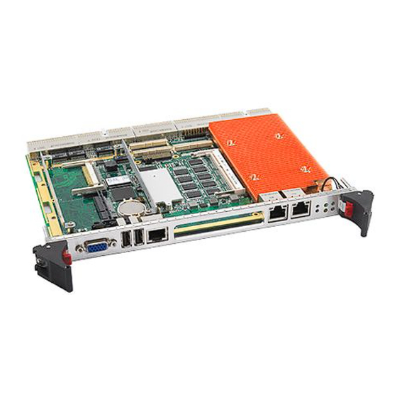
- Page 1 User Manual MIC-3395 ® 6U CompactPCI Generation ® Intel Core™ i3/i5/i7 Processor Blade with ECC support...
- Page 2 No part of this manual may be reproduced, copied, translated or transmitted in any form or by any means without the prior written permission of Advantech Co., Ltd. Information provided in this manual is intended to be accurate and reliable. How- ever, Advantech Co., Ltd.
- Page 3 Class I, Division 2, Groups A, B, C and D indoor hazards. Technical Support and Assistance Visit the Advantech website at http://support.advantech.com where you can find the latest information about the product. Contact your distributor, sales representative, or Advantech's customer service center for technical support if you need additional assistance.
- Page 4 Before setting up the system, check that the items listed below are included and in good condition. If any item does not accord with the table, please contact your dealer immediately. MIC-3395 all-in-one single board computer (CPU heatsink and PCH heatsink included) x1 Daughter board for SATA HDD (Assembled) x1 ...
- Page 5 The sound pressure level at the operator's position according to IEC 704-1:1982 is no more than 70 dB (A). DISCLAIMER: This set of instructions is given according to IEC 704-1. Advantech disclaims all responsibility for the accuracy of any statements contained herein.
- Page 6 We Appreciate Your Input Please let us know of any aspect of this product, including the manual, which could use improvement or correction. We appreciate your valuable input in helping make our products better. MIC-3395 User Manual...
- Page 7 Figure 1.6 SAS Configuration Scenario 2 - External Drive Array .. Figure 1.7 SAS Configuration Scenario 3 - Individual Drives ..14 Figure 1.8 Complete Assembly of MIC-3395 with SATA HDD .. 15 Figure 1.9 Fasten Screws on the SATA HDD Bracket ....16 Figure 1.10Insert SATA HDD into SATA Connector....
- Page 8 Figure A.1 RJ1 LAN1 Indicator ..........68 Figure A.2 RJ2 LAN2 Indicator ..........68 Appendix B Programming the Watchdog Timer . 71 Appendix C FPGA ..........73 Table C.1: LPC I/O Register Addresses ........74 Appendix D Glossary..........75 MIC-3395 User Manual viii...
- Page 9 Chapter Hardware Configuration This chapter describes how to configure MIC-3395 hardware.
- Page 10 The MIC-3395 is compliant with PICMG 2.0 Rev. 3.0. It supports a 64-bit / 66 MHz or 33MHz PCI bus for up to 7 CompactPCI slots at 3.3 V or 5 V VIO. The MIC-3395 is hot-swap compliant (PICMG 2.1) and conforms to the CompactPCI Packet Switching Backplane specification (PICMG 2.16) as well as the CompactPCI System Manage-...
- Page 11 1.2.6 Memory The MIC-3395 has up to 4 GB of onboard with ECC support DDR3 memory. It also has one 240-pin SO-DIMM sockets that can accommodate an additional 2GB of memory. The following table shows a list of SO-DIMM modules that have been tested on the MIC-3395.
- Page 12 I/O module via the J5 connector. 1.2.10 USB Port Two USB 2.0 compliant ports with fuse protection are provided. Both ports are routed to front panel connectors on the MIC-3395 and to the rear I/O module via the J5 con- nector. 1.2.11 LEDs Four LEDs are provided on the front panel as follows: One bi-color LED (blue/yellow) indicates hot swap and HDD activity.
- Page 13 1.2.13 Optional Rear I/O Modules The RIO-3315 is the optional RTM (also known as rear I/O module) for the MIC-3395. It offers a wide variety of I/O features, such as two or four RJ45 LAN ports, two COM ports, two VGA ports, two USB2.0 ports, one P/S2 port, and one Mini-SAS port for the RIO-3315-A1E model.
- Page 14 Additional I/O or co-processing functionality is supported by add-on PCI Express Mezzanine Cards (XMC) or PCI Mezzanine Cards (PMC). MIC-3395 supports one XMC site via PCI Express x8 bus. The XMC slot support one x8 PCI Express gen2 and 10G SFP XMC module of MIC-3666.
- Page 15 1.2.22 IPMI The MIC-3395 uses the Intelligent Platform Management Interface (IPMI) to monitor the health of an entire system. A Renesas H8S/2167 microcontroller provides BMC functionality to interface between system management software and platform hard- ware. The MIC-3395 implements fully-compliant IPMI 2.0 functionality and conforms to the PICMG 2.9 R1.0 specification.
- Page 16 Figure 1.1 MIC-3395 Functional Block Diagram Jumpers and Switches Table 1.4 and table 1.5 list the jumper and switch functions. Read this section care- fully before changing the jumper and switch settings on your MIC-3395 board. Table 1.4: MIC-3395 Jumper Descriptions Number...
- Page 17 JP11 (1-2) for +3.3 V JP11 (2-3) for +5 V Figure 1.2 JP11 for PMC VIO (+3.3 V or +5 V) 1.4.3 LCD Power Setting (JP3) Table 1.7: JP3 LCD Power Voltage Setting Default 3.3 V JP3 (2-3) JP3 (1-2) MIC-3395 User Manual...
- Page 18 When either front panel COM, RTM COM1 or RTM COM2 is connected to the BMC, the BMC firmware can be re-programmed by setting switch 1 and switch 2 to “BMC Program” mode. Table 1.10: SW1-1 PCI Bridge Master/Drone Mode SW1-1 Default Master Mode SW1-1 Drone Mode MIC-3395 User Manual...
- Page 19 Table 1.12: SW4 External Mini-SAS Port/Internal SAS Interface Default External Mini-SAS 4x Port Internal SATA ports 1 (SAS Port0) 2 (SAS Port1) 3 (SAS Port2) 4 (SAS Port3) Table 1.13: SW3 & SW5 COM2 Default RS232 RS422 MIC-3395 User Manual...
- Page 20 USB2 USB1 BMC Reset Button LAN1 LAN2 XMC/PMC Platform Reset Button BMC LED (yellow) HDD/Hot Swap LED (yellow/blue) Figure 1.3 MIC-3395 Front Panel Ports, Indicators and Buttons Power LED (green) USB1 USB2 LAN1 LAN2 DVI1 DVI2 HDD LED (yellow) Mini-SAS (RIO-3315-A1E only) PS/2 Figure 1.4 RIO-3315 Front Panel Ports and Indicators...
- Page 21 3315-A1E supports two on-board USB ports. The USB interface provides complete plug and play, hot attach/detach for up to 127 external devices. The MIC-3395 USB interface complies with USB specification R2.0 and is fuse protected (5 V @ 1.1 A).
- Page 22 Keep the board in its antistatic packaging when it is not installed in the chassis, and place it on a static dissipative mat when you are working with it. Wear a grounding wrist strap for continuous protection. MIC-3395 User Manual...
- Page 23 We recommend that you perform assembly at an anti-static workbench. 1.7.1 HDD Installation Steps The MIC-3395 supports 2.5” SATA hard disk drive. The SATA HDD daughter board is not assembled on the MIC-3395. The following steps illustrate the installation of the SATA HDD.
- Page 24 Align the HDD bracket on the side of HDD and fasten 4pcs M2.5 screw on the bracket. Figure 1.9 Fasten Screws on the SATA HDD Bracket Put the SATA HDD with bracket on the post and insert SATA HDD into SATA connector. Figure 1.10 Insert SATA HDD into SATA Connector MIC-3395 User Manual...
- Page 25 Software Support Windows 7, Windows XP, Windows 2000, Windows 2003 and Red Hat Enterprise Linux have been fully tested on the MIC-3395. Please contact your local sales repre- sentative for details on support for other operating systems. MIC-3395 User Manual...
- Page 26 MIC-3395 User Manual...
- Page 27 Chapter AMI BIOS Setup This chapter describes how to configure the AMI BIOS.
- Page 28 Figure 2.1 Setup Program Initial Screen BIOS Setup The MIC-3395 Series system has AMI BIOS built in, with a CMOS SETUP utility that allows users to configure required settings or to activate certain system features. The CMOS SETUP saves the configuration in the CMOS RAM of the motherboard.
- Page 29 BIOS supporting the CPU. If there is no number assigned to the patch code, please contact an Advantech application engineer to obtain an up-to-date patch code file. This will ensure that the CPU’s system status is valid. After ensuring that you have a number assigned to the patch code, press <DEL>...
- Page 30 2.3.2 Advanced BIOS Features Setup Select the Advanced tab from the MIC-3395 setup screen to enter the Advanced BIOS Setup screen. You can select any of the items in the left frame of the screen, such as CPU Configuration, to go to the sub menu for that item. You can display an Advanced BIOS Setup option by highlighting it using the <Arrow>...
- Page 31 In case of multiple option ROMs (Legacy and EFI Compatible), specifies what PCI option ROM to launch. Extended Synch “Enabled” allows generation of extended synchronization patterns. 2.3.2.2 ACPI Setting Figure 2.5 ACPI Settings Enable ACPI Auto Configuration Enable or disable BIOS ACPI auto configuration. MIC-3395 User Manual...
- Page 32 This allows the system to be awakened from an ACPI sleep state by a wake-up signal from a modem, which supports wake-up function. 2.3.2.3 CPU Configuration Figure 2.6 CPU Configuration Hyper-Treading This item allows you to enable or disable Intel Hyper Threading technology. MIC-3395 User Manual...
- Page 33 2.3.2.4 SATA Configuration Figure 2.7 SATA Configuration SATA Controller This item appears only by setting SATA mode to "IDE Mode". [Disabled] Disable SATA function. MIC-3395 User Manual...
- Page 34 2.3.2.5 Intel TXT Configuration Figure 2.8 Intel TXT Configuration Secure Mode Extension (SMX) Intel TXT Configuration This item allows to enabling or disabling Intel Trusted Execution Technology. MIC-3395 User Manual...
- Page 35 This is a workaround item for any OS without EHCI hand-off support. Device Reset time-out USB mass storage device start unit command time out. Mass Storage Devices Shows the USB mass storage devices’ detailed information. MIC-3395 User Manual...
- Page 36 2.3.2.7 Super IO Configuration Figure 2.10 Super IO Configuration Serial Port 1/2 Configuration For serial port 1/2, IRQ/IO mode resource configuration, users can choose IRQ, IO and MODE. MIC-3395 User Manual...
- Page 37 Figure 2.11 Serial Port 1/2 Configuration CIR Controller Configuration Figure 2.12 CIR Controller Configuration MIC-3395 User Manual...
- Page 38 Figure 2.13 PC Health Status 2.3.2.9 Console Redirection Setting Figure 2.14 Console Redirection Setting Console Redirection This item allows users to enable or disable console redirection or Microsoft Win- dows Emergency Management Services (EMS). MIC-3395 User Manual...
- Page 39 Select the port for Microsoft Windows Emergency Management Services (EMS) to allow for remote management of a Windows Server OS. Figure 2.16 Terminal Type Terminal Type VT-UTF8 is the preferred terminal type for out-of-band management. The next best choice is VT100+ and then VT100. MIC-3395 User Manual...
- Page 40 Set timer to wait before sending ASF_GET_BOOT_OPTIONS. Activated Remote Assistance Process This item allows users to enable or disable Alert Specification Format. USB Configure This item allows users to enable or disable USB Configure Function. MIC-3395 User Manual...
- Page 41 Figure 2.18 Intel Anti-Theft Technology ME FW Image Re-Flash This item allows users to enable or disable ME FW image re-flash function. MIC-3395 User Manual...
- Page 42 Figure 2.19 ME FW Image Re-Flash MIC-3395 User Manual...
- Page 43 2.3.2.11 Switchable Graphics Figure 2.20 Switchable Graphics SG Mode Select This item allows users to select switchable graphics mode. MIC-3395 User Manual...
- Page 44 The Chipset Setup screens are shown below. The sub menus are described on the following pages. 2.3.3.1 PCH-IO Configuration Figure 2.21 PCH-IO Configuration PCH LAN Controller Enable or disable PCH LAN controller. MIC-3395 User Manual...
- Page 45 This item allows users to select off, on and last state. 2.3.3.2 North Bridge Configuration System Agent (SA) Configuration Figure 2.22 System Agent (SA) Configuration – VT-d This item allows users to enable or disable VT-d. NB PCIe Configuration MIC-3395 User Manual...
- Page 46 PEG0 - Gen x Select PEG0 speed. – Always enabled PEG This item allows users to enable or disable PEG always. – PEG ASPM This item allows users to enable or disable PEG ASPM. Graphic Configuration MIC-3395 User Manual...
- Page 47 Figure 2.24 Graphic Configuration – Primary Display This item allows users to select which graphic controller to use as the primary boot device. LCD Control MIC-3395 User Manual...
- Page 48 Select boot display device at post stage. – LCD Panel Type This item allows users to select panel resolution. – Panel Scaling This item allows users to enable or disable panel scaling. – Active LFP This item allows users to select LFP configuration. MIC-3395 User Manual...
- Page 49 2.3.3.3 PCI Express Ports Configuration Figure 2.26 PCI Express Ports Configuration Enable or disable PCI Express Clock Gating for each root port. 2.3.3.4 Memory Configuration MIC-3395 User Manual...
- Page 50 Select DIMM timing profile that should be used. Channel A/B DIMM Control Enable or disable DIMMs on channel A or B. 2.3.3.5 Memory Thermal Configuration Figure 2.28 Memory Thermal Configuration Enable or disable memory thermal management. MIC-3395 User Manual...
- Page 51 2.3.3.6 USB Configuration Figure 2.29 USB Configuration Disable / Enable the USB controller (EHCI #1) and (EHCI #2) and allow users to dis- able/ enable USB ports. 2.3.4 Boot Setting Figure 2.30 Boot Setting MIC-3395 User Manual...
- Page 52 Enable/disable option for ROM to trap into 19. 2.3.4.8 Boot Option Priority Boot Option #1 Boot Option #2 Show the boot device choices. 2.3.4.9 Hard Drive BBS Priorities Select the main hard disk device type to be a boot hard drive. MIC-3395 User Manual...
- Page 53 Select this option and press <ENTER> to access the sub menu, and then type in the password. Set the Administrator password. 2.3.5.2 User Password Select this option and press <ENTER> to access the sub menu, and then type in the password. Set the User Password. MIC-3395 User Manual...
- Page 54 2.3.6 PXE Boot Setting 2.3.6.1 Launch PXE OpROM Figure 2.32 Launch PXE OpROM setting Enable Launch PXE OpROM 2.3.6.2 Save Changes and Reset Figure 2.33 Save changes and reset MIC-3395 User Manual...
- Page 55 2.3.6.3 Choose boot option priority MIC-3395 User Manual...
- Page 56 Note 1: Network Device BBS Priorities Note 2: Hard Drive BBS Priorities MIC-3395 User Manual...
- Page 57 Figure 2.34 Boot option priority 2.3.6.4 Save Changes and Reset again Figure 2.35 Save changes and reset MIC-3395 User Manual...
- Page 58 BIOS setup menu and reboot the computer to take effect all system configuration parameters. Select Exit Saving Changes from the Exit menu and press <Enter>. The follow- ing message appears: Save Configuration Changes and Exit Now? [Ok] [Can- cel] Select Ok or cancel. MIC-3395 User Manual...
- Page 59 Defaults from the Exit menu and press <Enter>. Save as User Default Save the all current settings as user default. Restore User Default Restore all settings to user default values. 2.3.7.4 Boot Override Show the boot device types on the system. MIC-3395 User Manual...
- Page 60 MIC-3395 User Manual...
- Page 61 Chapter IPMI for the MIC-3395 This chapter describes IPMI con- figuration for the MIC-3395.
- Page 62 Introduction The MIC-3395 fully supports the IPMI 2.0 interface and the PICMG 2.9 R1.0 specifi- cation. The Renesas H8S/2167 has been implemented as the IPMI controller / Base- board Management Controller (BMC) to run firmware and collect information. The MIC-3395 IPMI firmware is sourced from Avocent, a provider of proven and tested IPMI implementations in a wide range of mission-critical applications.
- Page 63 0x07 3.3.2 BMC Device and Messaging Interfaces The BMC messaging interfaces comply with the Intelligent Platform Management Interface Specification, Version 2.0. The MIC-3395 provides 4 messaging interface channels. LPC/KCS channel: Connects the H8S/2167 to the system LPC bus. Firmware sets 1 host interface over LPC: KCS for SMS.
- Page 64 SEL Device Command NetFn Mandatory/Optional Get SEL Info Storage Storage 0x40 M Reserve SEL Storage Storage 0x42 O Get SEL Entry Storage Storage 0x43 M Get SEL Time Storage Storage 0x48 M Set SEL Time Storage Storage 0x49 M MIC-3395 User Manual...
- Page 65 3.3.8 FRU Data The MIC-3395 supports the IPMI FRU function to store accessible multiple sets of non-volatile Field Replaceable Unit (FRU) information in FRU EEPROM. The FRU data includes information such as serial number, part number, model, and asset tag.
- Page 66 UC, UNR Temp Note! A chassis intruder sensor is not used on the MIC-3395 platform. Power failure sensor type "C0h" indicates a power failure event. Apart from the following list of sensors, other sensors should be re-ini- tialized when the system is powered on or reset.
- Page 67 Get Sensor Reading 0x2d 3.3.10 Serial/Modem Device Commands Table 3.13: Serial modem Device Commands Mandatory / Serial/Modem Device Command NetFn Optional Set Serial/Modem Configuration Parameters Transport 0x10 Get Serial/Modem Configuration Parameters Transport 0x11 Set Serial/Modem Mux Transport 0x12 MIC-3395 User Manual...
- Page 68 BMC Reset The BMC can initiate a graceful shutdown of the MIC-3395 by issuing a short pulse (~500 ms) on the power button signal to the ACPI controller when commanded through its host, OOB, or IPMB channels. It can also initiate a graceful shutdown from a Graceful Shutdown Event from the CMM or a Handle OPEN event.
- Page 69 Appendix Pin Assignments This appendix describes pin assignments.
- Page 70 C/BE(3)# IDSEL PAD(23) PAD(22) PAD(26) V(I/O) PAD(25) PAD(24) PAD(30) PAD(29) PAD(28) PAD(27) PRESENT REQ0# 3.3V CLK0 PAD(31) PCI_RST# GNT0# IPMB_P HEALTHY# V(I/O) INTP INTS INTA# INTB# INTC# INTD# -12V TRST# Note! NC: No Connection #: Active Low MIC-3395 User Manual...
- Page 71 PAD(53) PAD(59) V(IO) PAD(58) PAD(57) PAD(63) PAD(62) PAD(61) PAD(60) C/BE(5)# GND/64EN# V(I/O) C/BE(4)# PAR64 V(I/O) C/BE(7)# C/BE(6)# CLK4 GNT3# REQ4# GNT4# CLK2 CLK3 GNT2# REQ3# SYSEN# CLK1 REQ1# GNT1# REQ2# Note! NC: No Connection #: Active Low MIC-3395 User Manual...
- Page 72 SATA4_RX- VCC3 SATA2_TX- SATA2_RX- GND GND VCC3 GND MDIB1+ MDIB1- MDIB3+ MDIB3- GND MDIB0+ MDIB0- MDIB2+ MDIB2- GND MDIA1+ MDIA1- MDIA3+ MDIA3- GND MDIA0+ MDIA0- MDIA2+ MDIA2- SATA_LED GND NC Note! NC: No Connection #: Active Low MIC-3395 User Manual...
- Page 73 LINE_JD LINEIN_L LVDS1_D0+ LINEOUT_L LINEIN_R LVDS1_D0- LINEOUT_R LOUT_L LVDS1_D1+ AUDIO_GND LOUT_R LVDS1_D1- DDI3_DVIPWR ADDIO_GND LVDS_DDC_CL LVDS1_D2+ LVDS_BKLTEN GND LVDS_DDC_D LVDS1_D2- LVDS_BKLTCTL GND J4_GPIO LVDS1_D3+ VBAT LCD_VDD J4_GPIO LVDS1_D3- PRST# LCD_VDD Note! NC: No Connection #: Active Low MIC-3395 User Manual...
- Page 74 2.16B_LINK1 18 GND UART2_RTS GND K-ACT# ACT# 000# 2.16B_LINK- 19 GND COM1_RX# COM1_CTS# COM2_DCD# COM2_TX# ACT# 20 GND COM1_TX# COM1_DSR# RTM_PRES# COM2_RTS# COM2_DTR# COM1_RTS 21 GND COM1_DTR# UART2_TXD COM2_CTS# COM2_RI# COM1_DC 22 GND COM1_RI# UART2_RXD COM2_DSR# COM2_RX# MIC-3395 User Manual...
- Page 75 PERX_N0 NC(MBIST#) PERX_P1 PERX_N1 VPWR(+5V) MPRESENT# NC(+3.3V_A PERX_P2 PERX_N2 PERX_P3 PERX_N3 VPWR(+5V) TBD_SDA PERX_P4 PERX_N4 PERX_P5 PERX_N5 VPWR(+5V) NC(MVMRO) GND TBD_SCLK PERX_P6 PERX_N6 PERX_P7 PERX_N7 FPGAIO1 CLK_100M CLK_100Mhz FPGAIO2 NC(WAKE#) NC(ROOT#) NC Table A.8: VCN1 VGA Connector MIC-3395 User Manual...
- Page 76 Table A.11: BT1 CMOS Battery BAT_VCC Table A.12: RJ1 LAN1 Connector LAN_MDI 0+ LAN_MDI 2- LAN_MDI 0- LAN_MDI 1- LAN_MDI 1+ LAN_MDI 3+ LAN_MDI 2+ LAN_MDI 3- Figure A.1 RJ1 LAN1 Indicator Figure A.2 RJ2 LAN2 Indicator MIC-3395 User Manual...
- Page 77 Indicates Master or Drone mode status PWR (Green) Indicates power status BMC HB (Yellow) Indicates BMC status (heart beat to indicate BMC active) Indicates IDE activity when yellow, or that the board is HDD/Hot Swap (Yellow/Blue) ready to be hot-swapped when blue. MIC-3395 User Manual...
- Page 78 MIC-3395 User Manual...
- Page 79 Appendix Programming the Watchdog Timer This appendix describes how to program the watchdog timer.
- Page 80 50 GOSUB 2000 REM Your application task #2, 60 OUT &H443, data REM Reset the timer 70 X=INP (&H444) REM, Disable the watchdog timer 80 END 1000 REM Subroutine #1, your application task 1070 RETURN 2000 REM Subroutine #2, your application task 2090 RETURN MIC-3395 User Manual...
- Page 81 Appendix FPGA This appendix describes FPGA configuration.
- Page 82 Debug Message: Boot time POST message FPGA I/O Registers The Advantech MIC-3395 FPGA communicates with main I/O spaces. The LPC unit is used to interconnect the Intel ICH9R LPC signals. The Debug Port Unit is used to decode POST codes. The Hot-Swap Out-Of-Service LED Control Unit is used to con- trol the blue LED during Hot-Insert and Hot-Remove.
- Page 83 Appendix Glossary...
- Page 84 Reliability, Availability, Serviceability, Usability and Manageability Rear Input/Output RS-232 An Interface specified by Electronic Industries Alliance Real Time Clock Rear Transition Module Single Board Computer SDRAM Synchronous DRAM Small From-factor Pluggable Serial Presence Detect SoftWare Ultra Low Voltage Extension Module MIC-3395 User Manual...
- Page 85 MIC-3395 User Manual...
- Page 86 No part of this publication may be reproduced in any form or by any means, electronic, photocopying, recording or otherwise, without prior written permis- sion of the publisher. All brand and product names are trademarks or registered trademarks of their respective companies. © Advantech Co., Ltd. 2012...
Need help?
Do you have a question about the MIC-3395 and is the answer not in the manual?
Questions and answers