Table of Contents
Advertisement
Quick Links
Advertisement
Table of Contents

Related Manuals for Advantech MIC-3393


Summary of Contents for Advantech MIC-3393
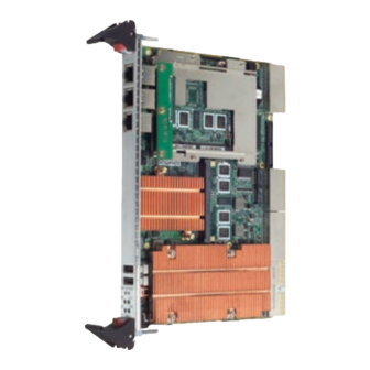
- Page 1 User Manual MIC-3393 ® ® 6U CompactPCI Intel Xeon Quad/Dual Core Processor Blade...
- Page 2 No part of this manual may be reproduced, copied, translated or transmitted in any form or by any means without the prior written permission of Advantech Co., Ltd. Information provided in this manual is intended to be accurate and reliable. How- ever, Advantech Co., Ltd.
-
Page 3: Declaration Of Conformity
Class I, Division 2, Groups A, B, C and D indoor hazards. Technical Support and Assistance Visit the Advantech web site at www.advantech.com/support where you can find the latest information about the product. Contact your distributor, sales representative, or Advantech's customer service center for technical support if you need additional assistance. -
Page 4: Packing List
Please send all such - in writing - to: support@advantech.com Packing List MIC-3393 all-in-one single board computer (CPU heatsink and MCH heatsink included) x1 Utility and user manual (PDF file) CD-ROM disc x1 Daughter board for SATA HDD and HDD tray (Assembled) x 1... -
Page 5: Safety Instructions
The sound pressure level at the operator's position according to IEC 704-1:1982 is no more than 70 dB (A). DISCLAIMER: This set of instructions is given according to IEC 704-1. Advantech disclaims all responsibility for the accuracy of any statements contained herein. - Page 6 We Appreciate Your Input Please let us know of any aspect of this product, including the manual, which could use improvement or correction. We appreciate your valuable input in helping make our products better. MIC-3393 User Manual...
-
Page 7: Table Of Contents
Introduction ....................2 Table 1.1: MIC-3393 Variants............2 Specifications .................... 2 1.2.1 CompactPCI Bus Interface ............2 1.2.2 CPU ....................3 Table 1.2: Intel processor selection for the MIC-3393....3 1.2.3 BIOS ..................... 3 1.2.4 Chipset..................3 1.2.5 Memory ..................4 Table 1.3: DDR2 200 Pin Registered SO-RDIMM Tested on the... - Page 8 ACPI Configuration ..............34 Figure 2.11ACPI setting ............. 34 Figure 2.12Advanced ACPI configuration ........34 2.4.8 AHCI Configuration..............35 Figure 2.13AHCI configuration ........... 35 2.4.9 Event Log Configuration ............. 36 Figure 2.14 Event log configuration..........36 MIC-3393 User Manual viii...
- Page 9 2.9.3 Discard Changes ................ 47 2.9.4 Load Optimal Defaults ..............47 2.9.5 Load Failsafe Defaults ..............48 Chapter IPMI for the MIC-3393 ......49 Introduction ..................... 50 Definitions ....................50 IPMI Function List ................... 50 3.3.1 IPMI Device Global Commands..........51 Table 3.1: Supported IPMI device global commands ....
- Page 10 Table C.2: Debug_Code [7:0] (LPC I/O address: 80H)....66 C.2.2 General Control and Status Registers ........67 C.2.3 General Purpose Registers ............70 Watchdog Timer..................71 C.3.1 Initial Watchdog ................71 C.3.2 Program Watchdog..............72 Appendix D Glossary..........73 MIC-3393 User Manual...
-
Page 11: Chapter 1 Hardware Configuration
Chapter Hardware Configuration This chapter describes how to configure MIC-3393 hardware. -
Page 12: Introduction
The MIC-3393 is compliant with PICMG 2.0 Rev. 3.0. It supports a 64-bit / 66 MHz or 33 MHz PCI bus for up to 8 CompactPCI slots at 3.3 V or 5 V VIO. The MIC-3393 is hot-swap compliant (PICMG 2.1) and conforms to the CompactPCI Packet Switching Backplane specification (PICMG 2.16) as well as the CompactPCI System Manage-... -
Page 13: Cpu
1.2.2 The MIC-3393 supports the 45nm 64-bit technology Intel Xeon Low Voltage (LV) / Ultra Low Voltage (ULV) processor family with clock frequencies up to 2.66GHz GHz and a Front-Side Bus (FSB) up to 1333 MHz. These processors are validated with the Intel 5100 MCH (San Clemente) chipset. -
Page 14: Memory
The MIC-3393 has 2GB of on-board ECC DDR2 SDRAM. It also has two 200-pin SO-DIMM sockets that can accommodate an additional 2GB of memory. The follow- ing table shows a list of SORDIMM modules that have been tested on the MIC-3393. Table 1.3: DDR2 200 Pin Registered SO-RDIMM Tested on the MIC-3393... -
Page 15: Storage Interface
Seven USB 2.0 compliant ports are provided. Two of them are routed to front panel connectors; one is routed to an on-board USB flash disk on the MIC-3393. The other four are routed to the RTM through the J3 connectors, two to the panels of the RTM, two to the on-board connectors. -
Page 16: Optional Rear I/O Modules
1.2.12 Optional Rear I/O Modules The RIO-3311 is the optional RTM (also known as rear I/O module) for the MIC-3393. It offers a wide variety of I/O features, such as three RJ45 LAN ports, two COM ports, one VGA port, two USB2.0 ports, one P/S2 port, and one Mini-SAS port for the RIO- 3311-A1E model. -
Page 17: Compact Mechanical Design
1.2.16 CompactPCI Bridge The MIC-3393 uses a PLX PCI 6540 universal bridge as a gateway to an intelligent subsystem. When configured as a system controller, the bridge acts as a standard transparent PCI-X-to-PCI bridge. As a peripheral controller it allows the local MIC-3393 processor to configure and control the onboard local subsystem indepen- dently from the CompactPCI bus host processor. -
Page 18: I/O Connectivity
FPGA. The PS2 (keyboard/mouse) is routed to the rear I/O module. 1.2.20 RTC and Battery The RTC module keeps the date and time. On the MIC-3393 model the RTC circuitry is connected to battery sources (CR2032M1S8-LF, 3V, 210mAH). 1.2.21 IPMI The MIC-3393 uses the Intelligent Platform Management Interface (IPMI) to monitor the health of an entire system. -
Page 19: Functional Block Diagram
Table 1.6 and table 1.7 list the jumper and switch functions. Figure 1.3 illustrates the jumper and switch locations. Read this section carefully before changing the jumper and switch settings on your MIC-3393 board. Table 1.6: MIC-3393 jumper descriptions Number... -
Page 20: Clear Cmos (Jp7)
Figure 1.3 MIC-3393 jumper and switch locations 1.4.1 Clear CMOS (JP7) This jumper is used to erase CMOS data. Follow the procedures below to clear the CMOS. Turn off the system. Close jumper JP7 (1-2) for about 3 seconds. Set jumper JP7 back to normal. -
Page 21: Switch Settings
BMC firmware can be re-programmed by setting switch 2 and switch 4 to "BMC Program" mode. Please refer to Table 1.12 for the setting of key 2, 3 and 4 of SW4-1 Table 1.11: SW3-1 PCI Bridge Master/Drone Mode Default Master Mode Drone Mode MIC-3393 User Manual... -
Page 22: For Bmc/Sio Uart
Table 1.13: SW1 External Mini-SAS port/Internal SAS interface Default External Mini-SAS 4x Port Internal SATA ports 1 (SAS Port0) 2 (SAS Port1) 3 (SAS Port2) 4 (SAS Port3) This switch is only available for the RIO-3311-A1E (supports SAS function) model. MIC-3393 User Manual... -
Page 23: Mic-3312-A1E Switch Setting
XMC2 2 x4 or PMC x4 Connector Definitions Table 1.15 lists the function of each connector and Figure 1.4 and 1.5 illustrate each connector location. Table 1.15: MIC-3393 connector descriptions Number Function CNSATA1 SATA HDD daughter board / CF daughter board connector... -
Page 24: Usb Connectors
1.5.1 USB Connectors The MIC-3393 provides up to seven Universal Serial Bus (USB) 2.0 channels. Two front panel USB ports, CNUSB1 and CNUSB2. One is routed to an on-board USB flash disk. Four other USB channels are routed to rear I/O via the J3 connector. Two on the panels, the other two are on-board connectors. -
Page 25: Ethernet Configuration
1.5.5 System Rest and BMC Reset Button The MIC-3393 provides a system reset button located on the front panel. The system reset button resets all payload and application-related circuitry. It does not rest the system management (IPMI) related circuitry. A separate BMC reset button on the front panel is provided for the BMC and related hardware. -
Page 26: Xmc / Pmc Connectors (Extension Module)
Keep the board in its antistatic packaging when it is not installed in the chassis, and place it on a static dissipative mat when you are working with it. Wear a grounding wrist strap for continuous protection. MIC-3393 User Manual... -
Page 27: Installation Steps
1.7.1 CompactFlash Daughter Board Installation Steps The MIC-3393 supports 2.5" SATA hard disk drive or CompactFlash. Either of them is occupied the same location. The SATA HDD daughter board is assembled on the MIC-3393, therefore installing a CF daughter board requires removing the SATA HDD daughter board first. -
Page 28: Figure 1.10Loosen Screws On The Sata Hdd Daughter Board
Loosen one M2.5 screw on the center of SATA HDD daughter board and four on the socket. Figure 1.10 Loosen screws on the SATA HDD Daughter Board Remove SATA HDD daughter board and socket Figure 1.11 Disassemble SATA HDD Daughter Board and Socket MIC-3393 User Manual... -
Page 29: Figure 1.12Assemble Cf Daughter Board
Align the CN2 connector of the CF daughter board to the CNSATA1 connector on the MIC-3393. Then fasten the four M2.5 (8mm) screws, as shown circled in red in the picture below. The screw circled in blue is used to attach the CF card. -
Page 30: Mic-3312 Extension Board Installation Steps
1.7.2 MIC-3312 Extension Board Installation Steps The MIC-3393B and MIC-3393C support the MIC-3312-A1E and MIC-3312-A2E extension boards respectively. Following steps illustrate the installation of the exten- sion boards. Figure 1.13 Complete assembly of MIC-3393C with MIC-3311-A2E MIC-3393 User Manual... -
Page 31: Figure 1.14Assemble Mic-3312-A1E
3393. Then fasten the six M2.5 (4mm) screws in the locations circled in red in Figure 1.14 below for the MIC-3312-A1E; or seven screws in the locations circled in red in Figure 1.15 for the MIC-3312-A2E. Figure 1.14 Assemble MIC-3312-A1E Figure 1.15 Assemble MIC-3312-A2E MIC-3393 User Manual... -
Page 32: Battery Replacement
1750129010 - BATTERY 3V/210 mAh with WIRE ASS'Y CR2032M1S8-LF Software Support Windows XP, Windows 2003 and Red Hat Enterprise Linux 5 have been fully tested on the MIC-3393. Please contact your local sales representative for details on sup- port for other operating systems. MIC-3393 User Manual... -
Page 33: Chapter 2 Ami Bios Setup
Chapter AMI BIOS Setup This chapter describes how to configure the AMI BIOS. -
Page 34: Introduction
BIOS settings and control the special features of the MIC-3393. The Setup program uses a number of menus for making changes and turning the special features on or off. This chapter describes the basic navigation of the MIC-3393 setup screens. -
Page 35: Entering Setup
BIOS supporting the CPU. If there is no number assigned, please contact an Advantech application engineer to obtain an up-to-date patch code file. This will ensure that the CPU's system status is valid. After ensuring that you have a number assigned to the patch code, press <DEL>... -
Page 36: Main Setup
Date using the <Arrow> keys. Enter new values through the keyboard. Press the <Tab> key or the <Arrow> keys to move between fields. The date must be entered in MM/DD/YY format. The time is entered in HH:MM:SS format. MIC-3393 User Manual... -
Page 37: Advanced Bios Features Setup
Advanced BIOS Features Setup Select the Advanced tab from the MIC-3393 setup screen to enter the Advanced BIOS Setup screen. You can select any of the items in the left frame of the screen, such as CPU Configuration, to go to the sub menu for that item. You can display an Advanced BIOS Setup option by highlighting it using the <Arrow>... -
Page 38: Cpu Configuration
"Enabled". 2.4.1.3 Intel SpeedStep Tech This item allows the processor to meet the instantaneous performance needs of the operation being performed, while minimizing power draw and heat dissipation. The default setting is "Enabled". MIC-3393 User Manual... -
Page 39: Lan Configuration
Select LAN3 mode Two options are available: RTM or PICMG 2.16. Used to select LAN3 connect to either RJ-45 LAN port on rear I/O or backplane via PICMG 2.16. The default setting for this item is set to "RTM". MIC-3393 User Manual... -
Page 40: Ide Configuration
BIOS. This option only functions under DOS. The default setting for this item is set to "Disabled". 2.4.3.6 IDE Detect Time Out (Sec) Select the time out value for detecting ATA/ATAPI devices. The default setting for this item is set to "35". MIC-3393 User Manual... -
Page 41: Super I/O Configuration
2.4.4 Super I/O Configuration Figure 2.8 Super I/O configuration 2.4.4.1 Serial Port1/2 Address Used to select Serial Port1 / Serial Port2 base addresses. MIC-3393 User Manual... -
Page 42: Hardware Health Configuration
2.4.5 Hardware Health Configuration Figure 2.9 Hardware health configuration System temperature, CPU temperature, VTIN temperature and voltage status are displayed in the Hardware Health Configuration. MIC-3393 User Manual... -
Page 43: Usb Configuration
EHCI driver. The default setting for this item is set to "Enabled". 2.4.6.4 USB Write Protect Disable or enable device write protection. Enable effective only if device is accessed through BIOS. The default setting for this item is set to "Enabled". MIC-3393 User Manual... -
Page 44: Acpi Configuration
ACPI APIC Support Enable or disable ACPI APIC table pointer to RSDT pointer list. The default setting is "Enabled. 2.4.7.4 AMI OEMB Table Enable or disable OEMB table pointer to R(X)SDT pointer list. The default setting is "Enabled". MIC-3393 User Manual... -
Page 45: Ahci Configuration
Serial ATA features such as Native Command Queuing and hot plug. The default setting is "Enabled". 2.4.8.2 AHCI CD/DVD Boot Time out Select the time out value for AHCI CD/DVD Boot devices. The default setting for this item is set to "35". MIC-3393 User Manual... -
Page 46: Event Log Configuration
2.4.9 Event Log Configuration Figure 2.14 Event log configuration 2.4.9.1 ECC Event Logging You can enable or disable ECC Event Logging. The default setting is "Enabled". MIC-3393 User Manual... -
Page 47: Mps Configuration
2.4.10 MPS Configuration Figure 2.15 MPS configuration 2.4.10.1 MPS Revision MPS allows the BIOS to configure the Multi-Processor Specification revision level. Some operation systems will require revision 1.1 for compatibility reasons. The default setting is "1.4". MIC-3393 User Manual... -
Page 48: Remote Access Configuration
Terminal Type Combo Key Support Select the target terminal type. 2.4.11.7 VT-UTF8 Enable or disable VT-UTF8 combination key support for ANSI/VT100 terminals. 2.4.11.8 Serial Over LAN Enable or disable Serial over LAN (SOL) function. The default setting is "Disabled". MIC-3393 User Manual... -
Page 49: Trusting Computing
TCG/TPM Support Enable or disable TPM TCG (TPM 1.1/1.2) support in BIOS. 2.4.12.2 Execute TPM Command Three options are available: "Don't change", "Disabled" or "Enabled". The default set- ting, "Don't Change" keeps TPM command to initial setting. MIC-3393 User Manual... -
Page 50: Pci/Pnp Setup
PCI/PnP Setup Select the PCI/PnP tab from the MIC-3393 setup screen to enter the Plug and Play BIOS Setup screen. You can display a Plug and Play BIOS Setup option by highlight- ing it using the <Arrow> keys. All Plug and Play BIOS Setup options are described in this section. -
Page 51: Boot Setup
Boot Setup Figure 2.19 Boot setup Note! "Hard Disk Drives" will only appear on the setup screen when at least one hard disk drive is connected to the MIC-3393. MIC-3393 User Manual... -
Page 52: Boot Settings Configuration
Wait for the F1 key to be pressed if an error occurs. 2.6.1.4 Interrupt 19 Capture Allow option ROMs to trap interrupt 19. This is required by some PCI cards that pro- vide a ROM based setup utility. MIC-3393 User Manual... -
Page 53: Security Setup
Security Setup Figure 2.21 Password configuration Select Security Setup from the MIC-3393 Setup main BIOS setup menu. All Security Setup options, such as password protection and virus protection, are described in this section. To access the sub menu for the following items, select the item and press <Enter>:... -
Page 54: Advanced Chipset Settings
Advanced Chipset Settings Figure 2.22 Advanced chipset settings MIC-3393 User Manual... -
Page 55: North Bridge Chipset Configuration
"Auto" or "Onboard VGA". Select "Auto", the external graphics card will be set as first priority. Select "Onboard VGA" to boot graphics from RTM only. 2.8.1.12 Read Completion Coalescing The default setting of this item is "Auto". MIC-3393 User Manual... -
Page 56: South Bridge Chipset Configuration
2.8.2.1 USB Functions The default setting is "12 USB Ports". 2.8.2.2 USB Port Configure The default setting is "6X6 USB Ports" 2.8.2.3 SMBUS Controller The default setting is "Enabled" 2.8.2.4 Spectrum Mode The default setting is "Enabled" MIC-3393 User Manual... -
Page 57: Exit Option
Discard changes done so far to any of the setup questions. 2.9.4 Load Optimal Defaults This loads the optimal defaults values for the MIC-3393 which allows optimum func- tionality and system performance. Select "Load Optimal Defaults" from the Exit menu and press <Enter>. -
Page 58: Load Failsafe Defaults
2.9.5 Load Failsafe Defaults This loads the basic defaults values for the MIC-3393 which may not work best for all computer applications. Select "Load Failsafe Defaults" from the Exit menu and press <Enter>. MIC-3393 User Manual... -
Page 59: Chapter 3 Ipmi For The Mic-3393
Chapter IPMI for the MIC-3393 This chapter describes IPMI con- figuration for the MIC-3393. -
Page 60: Introduction
Introduction The MIC-3393 fully supports the IPMI 2.0 interface and the PICMG 2.9 R1.0 specifi- cation. The Renesas H8S/2167 has been implemented as the IPMI controller / Base- board Management Controller (BMC) to run firmware and collect information. The MIC-3393 IPMI firmware is sourced from Avocent, a provider of proven and tested IPMI implementations in a wide range of mission-critical applications. -
Page 61: Ipmi Device Global Commands
3.3.2 BMC Device and Messaging Interfaces The BMC messaging interfaces comply with the Intelligent Platform Management Interface Specification, Version 2.0. The MIC-3393 provides 4 messaging interface channels. LPC/KCS channel: Connects the H8S/2167 to the system LPC bus. Firmware sets 1 host interface over LPC: KCS for SMS. -
Page 62: Bmc Watchdog Timer Commands
Table 3.7: PEF and alerting commands PEF and Alerting Command NetFn Mandatory/Optional Get PEF Capabilities 0x10 Arm PEF Postpone Timer 0x11 Get PEF Configuration Parameters 0x13 Set Last Processed Event ID 0x14 Get Last Processed Event ID 0x15 MIC-3393 User Manual... -
Page 63: Sel Device Commands
3.3.8 FRU Data The MIC-3393 supports the IPMI FRU function to store accessible multiple sets of non-volatile Field Replaceable Unit (FRU) information in FRU EEPROM. The FRU data includes information such as serial number, part number, model, and asset tag. -
Page 64: Sensor And Threshold Configuration
LNC,UC LNC,UC Note! A chassis intruder sensor is not used on the MIC-3393 platform. Power failure sensor type "C0h" indicates a power failure event. Apart from the following list of sensors, other sensors should be reinitial- ized when the system is powered on or reset. -
Page 65: Serial Modem Device Commands
Table 3.14: Serial modem Table 3.15: Table 3.16: Table 3.17: device commands Serial Modem Device Command NetFn Mandatory/Optional Set serial modem configuration Transport 0x10 parameters Get Serial Modem Configuration Transport 0x11 Parameters Set Serial Modem Mux Transport 0x12 MIC-3393 User Manual... -
Page 66: Bmc Reset
BMC Reset The BMC can initiate a graceful shutdown of the MIC-3393 by issuing a short pulse (~500 ms) on the power button signal to the ACPI controller when commanded through its host, OOB, or IPMB channels as well as from a Graceful Shutdown Event from the CMM or a Handle OPEN event. -
Page 67: Appendix A Pin Assignments
Appendix Pin Assignments This appendix describes pin assignments. -
Page 68: J1 Connector
C/BE(3)# IDSEL AD(23) AD(22) AD(26) V(I/O) AD(25) AD(24) AD(30) AD(29) AD(28) AD(27) REQ0# PRESENT# 3.3V CLK0 AD(31) RST# GNT0# IPMB_PWR HEALTHY# V(I/O) INTP INTS INTA# INTB# INTC# INTD# £¦12V £´12V Note! NC: No Connect #: Active Low MIC-3393 User Manual... -
Page 69: J2 Connector
AD(54) AD(53) AD(59) V(IO) AD(58) AD(57) AD(63) AD(62) AD(61) AD(60) C/BE(5)# V(I/O) C/BE(4)# PAR64 V(I/O) C/BE(7) C/BE(6)# CLK4 GNT3# REQ4# GNT4# CLK2 CLK3 SYSEN#(2) GNT2# REO3# CLK1 REO1# GNT1# REO2# Note! NC: No Connect #: Active Low MIC-3393 User Manual... -
Page 70: J3 Connector
GND VCC3 VCC3 KBCLK MSCLK RIO_SATA_LED# GND GND NC GND MDIB1+ MDIB1- MDIB3+ MDIB3- GND MDIB0+ MDIB0- MDIB2+ MDIB2- GND MDIA1+ MDIA1- MDIA3+ MDIA3- GND MDIA0+ MDIA0- MDIA2+ MDIA2- GND NC Note! NC: No Connect #: Active Low MIC-3393 User Manual... -
Page 71: J5 Connector
CLK_SAS- ACT# GND GND LAN1_MDI3- NC GND SAS_RX_N1 SAS_TX_N1 LAN1_MDI3+ LAN1_SPEE PLTRST# D_1000# GND SASRX_P1 SAS_TX_P1 LAN1_SPEE RTM_PRES# D_100# GND GND LAN1_LNK/ RTM_GPIO ACT# GND SAS_RX_N0 SAS_TX_N0 GND SAS_RX_P0 SAS_TX_P0 Note! NC: No Connect #: Active Low MIC-3393 User Manual... -
Page 72: Other Connectors
Indicates Master or Drone mode status PWR (Green) Indicates power status BMC HB (Yellow) Indicates BMC status (heart beat to indicate BMC active) HDD/Hot Swap (Yellow/Blue) Indicates IDE activity when yellow, or that the board is ready to be hot-swapped when blue. MIC-3393 User Manual... -
Page 73: Appendix B Programming The Watchdog Timer
Appendix Programming the Watchdog Timer This appendix describes how to program the watchdog timer. -
Page 74: Watchdog Timer Programming Procedure
50 GOSUB 2000 REM Your application task #2, 60 OUT &H443, data REM Reset the timer 70 X=INP (&H444) REM, Disable the watchdog timer 80 END 1000 REM Subroutine #1, your application task 1070 RETURN 2000 REM Subroutine #2, your application task 2090 RETURN MIC-3393 User Manual... -
Page 75: Fpga
Appendix FPGA This appendix describes FPGA configuration. -
Page 76: Features
Debug Message: Boot time POST message FPGA I/O Registers The Advantech MIC-3393 FPGA communicates with main I/O spaces. The LPC unit is used to interconnect the Intel ICH9R LPC signals. The Debug Port Unit is used to decode POST codes. The Hot-Swap Out-Of-Service LED Control Unit is used to con- trol the blue LED during Hot-Insert and Hot-Remove. -
Page 77: General Control And Status Registers
Name: PRESENT Address-Offset: 0x04 H8 Address: 0xFFC004 LPC Address: R/W (Type) Default Bit Position Mnemonic Description 7 : 2 Reserved XTM_PRES XTM connected : '1' = XTM present RO RTM connected : '1' = RTM RTM_PRES present MIC-3393 User Manual... - Page 78 R/W (Type) Default Bit Position Mnemonic Description 7 : 0 watch dog timer value 0xFF Name: WDG_disable Address-Offset: H8 Address: LPC Address: 0x444 Bit Position Mnemonic Description R/W (Type) Default 7 : 0 watch dog timer value MIC-3393 User Manual...
- Page 79 7 : 4 Reserved SOL control : Current SOL UART select SOL_REG '0' - select SIO_UART1. '1' - select SIO_UART2. Bit D1 Function enable/disable Enable/Dis- '0' - Bit D1 disabled. able D1 '1' - Bit D1 enabled. MIC-3393 User Manual...
-
Page 80: General Purpose Registers
Bit Position Mnemonic Description R/W (Type) Default 0x 7 : 0 MAJ_REV FPGA major revision This register holds the major revision ID. Major revision changes announcing design changes and additions with impact to the FPGA related firmware and application. MIC-3393 User Manual... -
Page 81: Watchdog Timer
'1' - Bit D1 enabled, FWH_SEL_ID can be controlled by the value of FWH_SEL_ID control : Current FWH_SEL_ flash select (FWH_SEL_ID) is con- trolled by the value of this bit if D2 is '1'. FWH_SEL_I Currently selected active D Status flash(FWH_SEL_ID) status MIC-3393 User Manual... -
Page 82: Program Watchdog
Bit Position Mnemonic Description Default 0x 7 : 0 watch dog timer value 0xFF Name: WDG_disable Address-Offset: H8 Address: LPC Address: 0x444 R/W (Type) Bit Position Mnemonic Description Default 0x 7 : 0 watch dog timer value MIC-3393 User Manual... -
Page 83: Appendix D Glossary
Appendix Glossary... - Page 84 Reliability, Availability, Serviceability, Usability and Manageability Rear Input/Output RS-232 An Interface specified by Electronic Industries Alliance Real Time Clock Rear Transition Module Single Board Computer SDRAM Synchronous DRAM Small From-factor Pluggable Serial Presence Detect SoftWare Ultra Low Voltage Extension Module MIC-3393 User Manual...
- Page 85 MIC-3393 User Manual...
- Page 86 No part of this publication may be reproduced in any form or by any means, electronic, photocopying, recording or otherwise, without prior written permis- sion of the publisher. All brand and product names are trademarks or registered trademarks of their respective companies. © Advantech Co., Ltd. 2009...
Need help?
Do you have a question about the MIC-3393 and is the answer not in the manual?
Questions and answers