Advertisement
Quick Links
Advertisement

Related Manuals for Titan Fitness PWR1-PWR2


Summary of Contents for Titan Fitness PWR1-PWR2
- Page 1 MPN(s): PWR1-PWR2 / SHPWR1-SHPWR2 SKU(s): 400100 / 400160 UPC(s): 765857424125 / 765857422152...
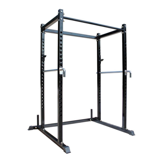
- Page 3 DESCRIPTION LOWER REAR BRACING JHOOKS LOWER SIDE BRACING PULL-UP BAR SPOTTER BAR PLASTIC END CAPS UPPER SIDE BRACING UPPER REAR BRACING UPRIGHT (10) SQUARE CAP (11) ROUND CAP (12) M12x75mm CARRIAGE BOLT (13) M12 FLANGED LOCK NUT (14) FLAT WASHER (15) M12x80 HEX BOLT...
- Page 4 ASSEMBY TIPS: BUILD ON A FLAT AND LEVEL SURFACE. AVOID TIGHTENING BOLTS COMPLETELY UNTIL THE RACK IS FULLY ASSEMBLED. STEP 1: ASSEMBLING THE BASE • Attach the two Lower Side Bracings (3) to the Lower Rear Bracing (1) using four M12x80 Hex Bolts (15), four Flat Washers (14), and four M12 Flanged Lock Nuts (13).
- Page 5 STEP 2: INSTALLING THE UPRIGHTS • Attach the four Uprights (9) to the Lower Side Bracing (3) using eight M12x75mm Carriage Bolts (12) and eight M12 Flanged Lock Nuts (13). The Carriage bolts are to be installed through the bottom side of the Lower Side Bracing with the Flanged Lock Nut on top.
- Page 6 STEP 3: ATTACHING THE UPPER SIDE BRACING • Attach the two Upper Side Bracings (7) to the top side of the Uprights (9) using eight M12x80mm Hex Bolts (15), eight Flat Washers (14), and eight M12 Flanged Lock Nuts (13). Note: One Flat Washers should be placed on each of the eight M12x80 Hex Bolts to seat on the outside of the upright with the Flanged Lock Nut on the inside of the Upper Side Bracing.
- Page 7 STEP 4: INSTALLING THE PULL-UP BAR AND REAR UPPER BRACING • Install the Pull-Up Bar (4) to the front two Uprights (9) using four M12x80mm Hex Bolts (15), four Flat Washers (14), and four M12 Flanged Lock Nuts (13). • Install the Upper Rear Bracing (8) to the two rear Uprights (9) using four M12x80mm Hex Bolts (15), four Flat Washers (14), and four M12 Flanged Lock Nuts (13).
- Page 8 STEP 5: TIGHTEN ALL HARDWARE • Once Steps 1-4 are complete, please tighten all hardware. All hardware should be tightened properly using a wrench and/or socket. The threading of the bolt must pass through the blue nylon ring on the Flanged Lock Nuts. All hardware should be firmly secured and seated to the Uprights, Bracings, and Pull-Up Bar to be used safely.
- Page 9 This concludes the PWR1-PWR2 / SHPWR1-SHPWR2 Owner’s Manual. If applicable to your product, make sure to tighten all nut-and-bolt combinations before use. Enjoy! DISCLAIMER This equipment must be used with care by capable and competent individuals under supervision, if necessary.
Need help?
Do you have a question about the PWR1-PWR2 and is the answer not in the manual?
Questions and answers