Advertisement
Quick Links
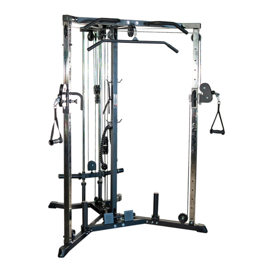
PLATE LOADED FUNCTIONAL TRAINER
PLTRAINER1-PLTRAINER2
400868
Operator's Manual
Read the Operator's Manual entirely. When you see this
symbol, the subsequent instructions and warnings are
serious follow without exception. Your life and the lives
of others depend on it!
Advertisement

Subscribe to Our Youtube Channel
Related Manuals for Titan Fitness PLTRAINER1


Summary of Contents for Titan Fitness PLTRAINER1
- Page 1 PLATE LOADED FUNCTIONAL TRAINER PLTRAINER1-PLTRAINER2 400868 Operator’s Manual Read the Operator’s Manual entirely. When you see this symbol, the subsequent instructions and warnings are serious follow without exception. Your life and the lives of others depend on it!
- Page 2 ASSEMBLY PARTS DIAGRAM / EXPLODED VIEW DESCRIPTION DESCRIPTION Base Frame (21) Long Pulley Plate Middle Base Frame (23) Three Pulley Fixing Plate Front Base Frame (24) Pulley Frame Right Base Frame (26) Small Handle Left Base Frame (27) Long Handle Upright Frame (28) Upper Cable Combination...
- Page 5 ASSEMBLY INSTRUCTIONS STEP 1 1. Install the Guide Rod (9) to Base Frame (1), using Hex Bolt M10*25(58). 2. Assemble the Base Frame (1), Middle Base Frame (2) and Front Base Frame (3) using Flat Washer Φ11*Φ20*2 (68), Flat Washer Φ10.5*Φ30*2.5 (69), Nut M10 (72) and Hex Bolt M10*70(62). PLEASE TIGHTEN ALL BOLTS.
- Page 6 ASSEMBLY INSTRUCTIONS STEP 2 Connect Right Base Frame (4), Left Base Frame (5), Middle Base Frame (2) and Front Base Frame (3), using Flat Washer Φ11*Φ20*2 (68), Flat Washer Φ10.5*Φ30*2.5 (69), Nut M10 (72), Hex Bolt M10*70 (62) and Hex Bolt M10*75 (63). PLEASE TIGHTEN ALL THE BOLTS.
- Page 7 ASSEMBLY INSTRUCTIONS STEP 3 1. Install Middle Upright Frame (8) on the Middle Base Frame (2), using Flat Washer Φ11*Φ20*2 (68), Nut M10 (72) and Hex Bolt M10*75 (63). 2. Put the Shock Absorber Rubber (37), Heighten Frame (15), Shock Absorber Rubber (51) and Bar Plate Holder on the Guide Rod (9).
- Page 8 ASSEMBLY INSTRUCTIONS STEP 4 1. Assemble the Top Cross Frame (7) on Middle Upright Frame (8) and Guide Rod (9), using Flat Washer Φ11*Φ20*2 (68), Nut M10 (72), Hex Bolt M8*25 (58) and Hex Bolt M10*75 (63). 2. Install the Fixing Frame (17) on the Handlebar Frame (12) using Flat Washer Φ9*Φ16*1.6 (67) and Hex Bolt M8*12 (56).
- Page 9 ASSEMBLY INSTRUCTIONS STEP 5 Install Right Cross Frame (10), Left Cross Frame (11) on Top Cross Frame (7) and Handle Bar Frame (12), using Flat Washer Φ11*Φ20*2 (68), Flat Washer Φ10.5*Φ30*2.5 (69), Nut M10 (72), Hex Bolt M10*70 (62)and Hex Bolt M10*75 (63).
-
Page 10: Bolts And Nuts
ASSEMBLY INSTRUCTIONS STEP 6 1. Put the Right Sliding Frame (13) and Left Sliding Frame (14) on Upright Frame (6). Please pay attention to ensure the Upright Frame (6) is aligned with the hollow sleeve (34) and not misaligned. 1. Install the Upright Frame (6) on Right &... - Page 11 ASSEMBLY INSTRUCTIONS STEP 7 1. Install the J-Hook (19) on the Middle Upright Frame (8) using Flat Washer Φ9*Φ16*1.6 (67) and Hex Bolt M8*12 (56). 2. Install the Upright Bar Plate Holder (20) on Right& Left Base Frame (4&5) using Flat Washer Φ11*Φ20*2 (68), Nut M10 (72), and Hex Bolt M10*70 (62).
- Page 12 ASSEMBLY INSTRUCTIONS STEP 8 1. Fixing the pulley (35) on the Top Cross Frame (7) using Pulley Spacer Bush (41), Flat Washer Φ11*Φ20*2 (68), Nut M10 (72), Hex Bolt M10*45 (60), Hex Bolt M10*65 (61) and Hex Bolt M10*75 (63). 2.
- Page 13 ASSEMBLY INSTRUCTIONS STEP 9 1. Fixing the pulley (35 & 36) on the Base Frame using Flat Washer Φ11*Φ20*2 (68), Nut M10 (72) and Hex Bolt M10*45 (60). 2. The Lower Cable (29) through each pulley (L)(M)(N)(O)(P) in turn as drawing, then fixing by Flat Washer Φ11*Φ20*2 (68), Nut M10 (72) and Hex Bolt M10*35 (59).
- Page 14 ASSEMBLY INSTRUCTIONS STEP 10 1. Fixing the pulley (35) on the Cross Frame, using Pulley Spacer Bush (41), Flat Washer Φ11*Φ20*2 (68), Nut M10 (72), Hex Bolt M10*45 (60) and Hex Bolt M10*65 (61). 2. Remove the Fixing frame (Z), Washer (Y) and Stopper (X) from the cable (30), then through each pulley (R)(S)(T)(U)(V)(W) in turn as drawing, and the stopper (X), Washer (Y) and Fixing frame (Z), using Flat Washer Φ11*Φ20*2 (68), Nut M10 (72) and Hex Bolt M10*35 (59).
- Page 15 ASSEMBLY INSTRUCTIONS STEP 11 Install all Accessories on the Machine.
- Page 16 CABLE ADJUSTMENT METHOD Make sure fix the cable on the first holes on both carriage Frames. We must screw into 15mm-20mm, at least 15mm. As shown in figure 3. If the cable is too long, please adjust to the appropriate position according to the following methods 1.
- Page 17 APPENDIX - FULL ASSEMBLY/EXPLODED VIEW/ FULL PARTS LIST...
- Page 18 DESCRIPTION DESCRIPTION SHOCK ABSORBER BASE FRAME (38) RUBBERΦ77*Φ47.5*13 MIDDLE BASE FRAME (39) END CAP Φ48*2 FRONT BASE FRAME (40) END CAP □50*2 RIGHT BASE FRAME (41) PULLEY SPACER BUSH LEFT BASE FRAME (42) FRONT PIPE SLEEVE UPRIGHT FRAME (43) RUBBER SLEEVE TOP CROSS FRAME (44) END CAP Φ25*2.5...
- Page 19 ACKNOWLEDGEMENT OF RISK AND RELEASE OF LIABILITY The use of any equipment, including this one, involves the potential risk of injury. Apart from any warranty claim that might be presented for a claimed defect in material or workmanship of the product, you accept and assume full responsibility for any and all injuries, damages (both economic and non-economic), and losses of any type, which may occur, and you fully and forever release and discharge Titan, its insurers, employees, officers, directors, associates, and agents from any and all claims, demands, damages,...
- Page 20 NEED HELP? CONTACT US FIRST. 1-888-410-1503 info@titan.fitness www.titan.fitness © 2021 Titan Brands...
Need help?
Do you have a question about the PLTRAINER1 and is the answer not in the manual?
Questions and answers