Table of Contents
Advertisement
Advertisement
Table of Contents

Subscribe to Our Youtube Channel
Related Manuals for Zimmer Hall MicroChoice System


Summary of Contents for Zimmer Hall MicroChoice System
- Page 1 ® ™ MicroChoice The Hall System Instruction Manual...
-
Page 3: Table Of Contents
Table of Contents Page General Warnings ......... . 2 MicroChoice ™... -
Page 4: General Warnings
GENERAL WARNINGS Prior to each use, all handpieces and accessories must be inspected for proper operation. The surgeon and all others in the area must always wear eye protection ® when operating any Hall Surgical equipment. Eye injury or blindness can result from dislodged drill bits, blades or bone/tooth fragments. - Page 5 10. Overheating might occur if the handpiece or accessory bearings are worn or are not kept clean. Continually check all parts of the handpiece and attachments for overheating. Discontinue use and return the equipment for service as necessary. Overheating can cause serious injury to the patient or operating room personnel.
-
Page 6: Microchoice Controller
MICROCHOICE CONTROLLER ™ ® The Hall MicroChoice Controller is designed and manufactured ® specifically to power only MicroChoice and levered Micro E handpieces. The MicroChoice Controller is designed to operate on grounded electrical power. Important Note: The Controller will not detect improper grounding between itself and the electrical outlet. - Page 7 Symbol Definitions: Power "OFF" Power "ON" Attention, consult accompanying documents Handpiece Connection Footswitch Connection Irrigation Pump Connection Type B, Class 1 Equipment Caution Flammable Anesthetics - Risk of explosion if used in the presence of flammable anesthetics.
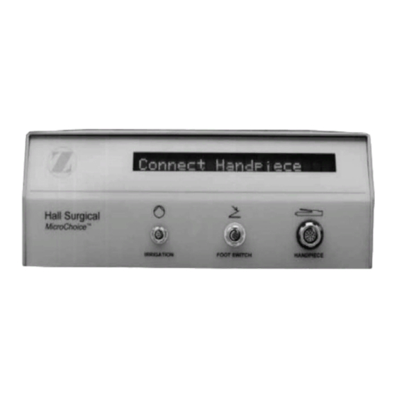
- Page 8 To Activate Controller: MicroChoice ™ Plug the power cord into the receptacle rear Controller. Plug remaining end of power cord into a standard grounded wall outlet. Once the power cord has been connected, no front panel lights should be activated. If the display panel is activated, depress the Power On/ Off switch to deactivate the system.
- Page 9 4(a) Once the chosen handpiece has been attached, activate the system by depressing the On/Off power switch on the back of the Controller. When power switch has been depressed, the display panel will display with HALL SURGICAL . Controller will go through a self- diagnostic check indicating the software version.
-
Page 10: General Handpiece Instructions
(c) Operation of the handpiece can begin by moving the Safe/Run Slide to the "run" position. Each handpiece will initially operate at its default setting. Desired settings can be stored in memory by following the instructions outlined in the Handpiece Mode Selection section (See Handpiece Mode Selection, pages 38 - 47, for default settings and "Day-to-Day"... - Page 11 (b) Firmly grasp both the connection end of the handpiece and the connector end of the Handpiece Cord. (c) The Handpiece Cord connector has been designed in a fashion where attachment can only occur orientation. Improper attachment of the cord is not possible.
- Page 12 To activate the handpiece, move the Safe/Run Slide forward. "Run" will visible through opening. The Controller will display the connected handpiece I.D. along with the maximum RPM or speed setting. Without any user input selections (see Handpiece Mode Selection instructions for available settings) the Controller will display the default setting and the handpiece will operate within this range.
-
Page 13: Microchoice High Speed Drill
HIGH SPEED DRILL Activation Lever Safe/Run Slide Twist Bur Lock Specifications: Operating Speed 100,000 rpm Maximum Maximum Speed Settings 10,000 to 100,000 rpm in 10,000 rpm increments Torque 2 in. oz. Bur Pull Out Force Exceeds 12.0 lbs. (5.4 kg.) Warning: Place Safe/Run Slide in the "safe"... - Page 14 To insert a bur, slide the appropriate bur guard over the end of the High Speed Drill. Be certain it is completely seated. Twist the bur lock to the "Open" position. Insert the bur to the safe line or until the bur seats completely.
-
Page 15: Microchoice Medium Speed Drill
MEDIUM SPEED DRILL Activation Lever Safe/Run Slide Twist Bur Lock Specifications: Operating Speed 25,000 rpm Maximum Maximum Speed Settings 1,000 to 25,000 rpm in 2,000 rpm increments Torque 6 in. oz. Bur Pull Out Force Exceeds 12.0 lbs. (5.4 kg.) Warning: Place Safe/Run Slide in the "safe"... - Page 16 To insert a bur, slide the appropriate bur guard over the end of the Medium Speed Drill. certain completely seated. Twist the bur lock to the "Open" position and insert the bur to the safe line or until the bur seats completely. To secure the bur, twist the bur lock until the red indicator dots are aligned in the "Lock"...
-
Page 17: Microchoice Drill Attachments/Accessories
DRILL ATTACHMENTS AND ACCESSORIES MicroChoice ™ High Speed and Medium Speed Drills Warning: Place handpiece in the "safe" position prior to connection with the attachment. Be certain the attachment/accessory is completely seated on the handpiece prior to each use. To use the MicroChoice Drill Attachments/Accessories: Open the handpiece collet to "Open"... - Page 18 20 ° and Extra-Long 20 ° Angle Attachments: long 5092 burs with the 20 ° Angle Attachment ® Caution: Use only Hall and only Hall extra-long 5093 burs with the Extra-Long 20 ° Attachment. Twist the bur lock on the attachment to the "Open"...
- Page 19 70 ° Surgical Head and 90 ° Angle Attachments: ® Caution: Use only Hall short 5090 and extra-short 5089 series burs with the 70 ° Contra-Angle Attachment and the 90 ° Angle Attachment. Place the bur in the opening on the attachment.
- Page 20 70 ° Dental Head The 70 ° Dental Head attachment uses friction grip burs only - size 1/16" or 1.58 mm in diameter. Friction grip burs are not marketed by Zimmer. They are available through dental supply dealers. Tissue Retractor Bur Guard:...
- Page 21 Laminectomy Bur Guard: Twist the bur lock to the "Open" position and insert the correct bur (5092-103 shown). Twist the bur lock until the red indicator dots are aligned in the "Lock" position. Slide the Laminectomy Guard over the bur and the end of the drill.
-
Page 22: Microchoice Low Speed Drill
LOW SPEED DRILL: Safe/Run Slide Specifications: Drill Head (single color band) Operating Speed 2,500 rpm Maximum Maximum Speed Settings 250 to 2,500 rpm in 250 rpm increments Torque 15 in. oz. Screw/Tap Head (two color bands) Operating Speed 30 rpm Maximum Maximum Speed Settings 2 to 30 rpm in 2 rpm increments Torque... - Page 23 Warnings: Place Safe/Run Slide in the "safe" position when not in use. Always operate the Low Speed Drill with the appropriate attachment. Check each bur before use in the Low Speed Drill. Never use a bent bur. Note: The Low Speed Drill accepts standard dental latch burs or ®...
- Page 24 Bur insertion and removal: Completely seat Angled Attachment on the Low Speed Drill. To insert bur: Press the rear portion of the head of the attachment, place the bur in the opening on the front of the attachment, insert and rotate the bur into place.
-
Page 25: Microchoice Reciprocating Saw
RECIPROCATING SAW Activation Lever Safe/Run Slide Blade Lock Nut Specifications: Operating Speed 17,000 cpm Maximum Speed Settings 20 - 100% in increments of 10% Stroke 1/10 in. (2.54 mm) Warning: Place Safe/Run Slide in the "safe" position when not in use. ®... - Page 26 To secure the blade: Twist the blade locking nut clockwise until completely tightened. Briefly activate the handpiece and retighten the blade locking nut. To secure round shank blades follow steps 1 and 2. Round shank blades can be seated at any position within a 360 °...
-
Page 27: Microchoice Sagittal Saw
SAGITTAL SAW Activation Lever Safe/Run Slide Collet Lock Mechanism Specifications: Operating Speed 20,000 cpm Maximum Speed Settings 20 - 100% in increments of 10% 4 ° arc Stroke Warning: Place Safe/Run Slide in the "safe" position when not in use. ®... - Page 28 Depress the opposite side of the handpiece collet area to lock the blade into position. Briefly activate the handpiece to verify that the blade is attached. Blades may be positioned at 45 ° intervals within a 180 ° arc. remove blades: Depress collet...
-
Page 29: Microchoice Oscillating Saw
OSCILLATING SAW Activation Lever Safe/Run Slide Collet Lock Mechanism Specifications: Operating Speed 25,000 cpm Maximum Speed Settings 20 - 100% in increments of 10% 8 ° arc Stroke Warning: Place Safe/Run Slide in the "safe" position when not in use. ®... - Page 30 Position the blade on the pins inside the collet. Twist collet lock mechanism so the arrows are again aligned in the "Lock" position to secure the blade. Briefly activate the handpiece to verify the blade is attached. Blades may be positioned at 45 °...
-
Page 31: Microchoice Wiredriver/Fixation Drill
WIREDRIVER/FIXATION DRILL Trigger Wireguard Control Receptacle Forward/Safe/Reverse Lever Specifications: Operating Speed 1,000 rpm, forward or reverse Maximum Speed Settings 100 to 1,000 rpm in 100 rpm increments Cannulated: Maximum .125 in. (3.2mm) diameter Warning: Place the Operating Switch in the "safe" position prior to the connection of any attachment. - Page 32 The handpiece is placed in the "safe" position by aligning the Operating Switch in the down position. The Forward/Safe/ Reverse Lever is directed towards "SAFE". Attach the Handpiece Cord per General Handpiece Instructions (pages 8 - 10). Wiredriver Attachment Specifications: Operating Speed 1,000 rpm either forward or reverse Maximum Speed 100 to 1,000 rpm...
- Page 33 Attach Wiredriver Attachment to the handpiece by orienting the two and pressing them until they "snap" together. The Wiredriver Attachment will accept threaded unthreaded wires from 0.028 to 0.062 in. (0.7mm to 1.6mm) in diameter. Insert the wire from the front or the rear of the handpiece.
- Page 34 Depress the Advancement Lever. Collet will regrip the wire for further advancement. The wire can be removed from the Wiredriver by releasing both the trigger and the Advancement Lever. To remove threaded wires from patient: Place the Operating Lever in the “safe”...
- Page 35 To insert the pin, push the lever forward. Grip the pin by squeezing the Advancement Lever. Depress trigger and drive the pin. To advance pin: Release the trigger stop rotation. Release Advancement Lever reposition handpiece up the pin until approximately 1 in. (2.5cm) of pin is exposed.
- Page 36 Attach Universal Drill Attachment to the handpiece by pressing the two until they "snap" together. Trinkle Shank Accessories Pull collet sleeve back. Align dimple on trinkle shank with black arrow on outer collet sleeve. Insert trinkle shank into collet. When trinkle shank is inserted, spring-loaded inner...
- Page 37 A. O. Drill Bits Align flat portion of the Quick Disconnect Drill Shank with the black arrow on the collet sleeve and insert into the collet. Insert the shank as far as it will go without pulling back the collet sleeve. Twist the shank to make sure it is aligned properly.
- Page 38 High Torque Jacobs Chuck Attachment Specifications: Operating Speed 275 rpm either forward or reverse Maximum Speed 25 to 275 rpm in Settings 25 rpm increments Attach the High Torque Jacobs Chuck Attachment to the handpiece by pressing the two until they "snap" together. Secure the item in the chuck with the chuck key (999-053).
-
Page 39: Micro E ® Handpiece Operation
® MICRO E HANDPIECE OPERATION ® Hall Micro E handpieces can be used in conjunction with the MicroChoice™ Controller. Warning: Place Safe/Run Slide in the "safe" position when not in use. Align the red indicator dot on the Handpiece Cord connector with the matching dot above the Handpiece receptacle. -
Page 40: Handpiece Mode Selection
HANDPIECE MODE SELECTION The MicroChoice™ Controller is equipped with a microcontroller which allows the user complete system control from within the sterile field. Speed and irrigation flow can be set and controlled by depressing the Mode Select Button located on the Handpiece Cord. Caution: Each handpiece has an initial or default speed and irrigation setting. - Page 41 Handpiece Default Settings: Handpiece Speed Irrigation High Speed Drill 100,000 rpm 100% Medium Speed Drill 25,000 rpm 100% Low Speed Drill Drill 2,500 rpm 100% Screw/Tap 30 rpm 100% Reciprocating Saw 17,000 cpm 100% Sagittal Saw 20,000 cpm 100% Oscillating Saw 25,000 cpm 100% Pencil Grip Wiredriver...
- Page 42 Changing the Default Speed Setting: Depress the Mode Select Button twice, within two (2) seconds, return Controller to display the speed setting (the speed setting will be blinking). The connected handpiece I.D. is displayed with its default speed setting (blinking). Depress the Mode Select Button until the desired speed setting...
- Page 43 Day-to-Day Memory Storage The MicroChoice™ Controller has the capability of "Day-to-Day" memory storage. "Day-to-Day" memory storage retains handpiece settings between Controller uses (even if Controller power is turned “Off”), and is only available when DIP switch number 1 is set to the "On" position. Make sure Controller is in the "OFF"...
- Page 44 To Set Irrigation Flow: Move the Safe/Run Slide to the "safe" position. Attach the Irrigation Cord to the Irrigation Pump and the Irrigation receptacle on the Controller. Turn the pump on. Rotate the flow control dial on the Irrigation Pump to the maximum setting.
- Page 45 The handpiece I.D. and the speed are displayed (speed will be blinking). Selection of a new maximum speed is possible. See Changing the Default Speed Setting (page 40). The Controller display will alternate between irrigation flow rate setting and the maximum speed setting. Connect Irrigation Tips and Tubing.
- Page 46 Low Speed Drill: Selection of the appropriate attachment and/or function. Move Safe/Run Slide to the "safe" position. Insert the Footswitch Cord into the Footswitch receptacle Controller (see Footswitch Instructions for additional information). Attach appropriate head to the Low Speed Drill.
- Page 47 Depress the Mode Select Button twice, within two (2) seconds. The SCREW TAP DRILL menu will display (DRILL will be blinking). Depress the Mode Select Button until desired function blinking. Discontinue pressing. The selected function will display with the maximum speed setting (blinking).
- Page 48 Wiredriver/Fixation Drill: Selection of the appropriate attachment. Place the Selector Switch in the "safe" position. Secure the appropriate attachment to the handpiece. 3. Depress the Mode Select Button twice, within seconds. The WIRE DRILL HTQ PIN menu will display (WIRE will be blinking). Depress the Mode Select Button until...
-
Page 49: Leverless Operation
LEVERLESS OPERATION The MicroChoice™ High Speed Drill, Medium Speed Drill, Reciprocating Saw, Sagittal Saw and Oscillating Saw can also be operated with the Footswitch. To remove the Handpiece Activation Lever: Place the Safe Slide in the "safe" position. Depress the Activation Lever on the ribbed portion. - Page 50 Cautions: Always remove the Handpiece Activation Lever when operating the handpiece by the Footswitch. If the Handpiece Activation Lever has not been removed, and the Footswitch is in use, depressing the Activation Lever will not control the handpiece until use of the Footswitch has been discontinued. Note: The Handpiece Activation Lever Cover (5020-070) can be attached to the area where the...
-
Page 51: Footswitch Operation
MICROCHOICE FOOTSWITCH CONTROL ™ Warning: Place the Safe Slide in the "safe" position when not in use. Warning: To avoid unintentional activation, unplug the Footswitch when using a levered handpiece. When the Footswitch is attached to the Controller it will remain active. Caution: The mode of activation initiated first, Activation Lever or Footswitch, has operational control of the handpiece even if the other is inadvertently depressed simultaneously. -
Page 52: Irrigation
For forward motion depress the right pedal. For reverse motion depress the left pedal. An audible beep will sound while the pedal is depressed indicating reverse motion. IRRIGATION ® The Hall Surgical Irrigation Pump should be utilized if irrigation is required. - Page 53 Attach the Irrigation Cord to the front of the Irrigation Pump. Connect the remaining end of the cord to the Irrigation receptacle on the MicroChoice™ Controller. Fully assemble Irrigation Tubing to the Irrigation Pump and the Handpiece Cord. Push Handpiece Clip on the handpiece.
-
Page 54: Controller Stand
For additional information about ® Irrigation set-up, refer to the Hall Irrigation Instruction Manual. If the Instruction Manual can not be located, contact Hall Surgical for information concerning these issues. Replacement Instruction Manuals are available. See Handpiece Mode Selection instructions for setting irrigation flow rates (page 38). -
Page 55: Care And Cleaning Instructions
CARE AND CLEANING INSTRUCTIONS Care and Cleaning Precautions: DO NOT LUBRICATE. Lubrication of the MicroChoice™ handpieces is not required. NEVER IMMERSE MicroChoice handpieces, cords or Footswitch. Immersion in any solution may permanently damage the handpiece or Footswitch from liquid entering the mechanical parts. Some solutions will corrode metal and delicate moving parts, and also may break down internal lubricants and/or insulation. - Page 56 Cleaning Instructions: It is recommended that the Handpiece Cord remain attached to the handpiece during cleaning. Remove prior to sterilization. Thoroughly scrub handpiece and attachments/ accessories with a soft brush and mild detergent. Remove all traces of blood and debris. Keeping the nose of the handpiece pointed downward, rinse under running water.
- Page 57 To dry, wipe surfaces with a clean, lint-free towel. It is best to use burs and blades only once. However, if burs or blades reused, clean cutting surfaces with a wire brush and mild detergent. Be certain that all surfaces are free of debris.
-
Page 58: Sterilization Recommendations
STERILIZATION RECOMMENDATIONS Handpiece Sterilization Recommendations: The MicroChoice™ System and attachments may be processed in a pre- vacuum steam sterilizer. Place the handpieces in an instrument tray or a fully perforated, wrapped container. Four MicroChoice Sterilization Trays are available for this purpose. The recommended exposure time for pre-vacuum steam sterilization is: Steam Pre-Vacuum Set temperature and corresponding exposure time:... - Page 59 MicroChoice™ Kit Configuration Sterilization Parameters: The recommended exposure time for pre-vacuum steam sterilization of a Microchoice System Kit is: Steam Pre-Vacuum Set temperature and corresponding exposure time: Temperature Exposure Time 270 ° - 272 ° F (132 ° - 133 ° C) 4 minutes Drying cycle of EIGHT (8) minutes minimum.
- Page 60 DO NOT use Ethylene Oxide sterilization. DO NOT immerse in liquid to cool. Cool by exposure to room temperature. DO NOT run handpieces while warm. Allow adequate time for handpiece cooling prior to surgery. ALWAYS sterilize the High Speed and Medium Speed Drills with the collet mechanism in the "Open"...
-
Page 61: Hall ® Surgical Instrument Warranty
® HALL SURGICAL INSTRUMENT WARRANTY Hall Surgical, Linvatec Corporation, a division of Zimmer ("Hall Surgical"), warrants to the first purchaser or lessee ("Customer") that the instrument and parts ("Instruments") have been tested, inspected, and shipped in proper working order, free of visible defects. - Page 62 The foregoing limited warranties do not apply to the following: Instruments which have in any way been tampered with, altered or misused. Instruments used with other than Hall Surgical authorized accessories and attachments. Instruments, including components or parts, not manufactured by Hall Surgical.
-
Page 63: Technical Specifications
TECHNICAL SPECIFICATIONS MICROCHOICE™ SYSTEM Controllers: 5020-020 and 5020-040 5020-Series Handpieces and accessories. ® (5040-Series Micro E handpieces may also be used with 5020-020 or 5020-040 Controllers.) Power Requirements, (Mains) 5020-020 100-120 VAC, 50-60~Hz, 2.5 A 5020-040 220-240 VAC, 50~Hz, 1.2 A Protection Classifications: (5020-040 only) Designed for Patient Applied, continuous operation with intermittent loading;... - Page 64 Protective Grounding: All models use ground protection. Use only with grounded line or mains supply and medical grade cord set (5039-003 AC Power Cord). Voltage Selection Means: Each Controller is factory pre-set for a specific voltage range. Make sure you have the correct setting for your local line (mains) supply.
-
Page 65: Calibration
Technical information for Service: ® No parts of this system are serviceable except by Hall Surgical or authorized service centers. Do not attempt to open the unit or make any repairs, this could render the unit unsafe. Environmental Conditions: Storage: -40 to +50°C, 10 to 100% non- condensing humidity, atmospheric pressure 500 to 1060 millibars. -
Page 66: Receiving/Periodic Inspection
RECEIVING/PERIODIC INSPECTION Read the user section of this manual to assure yourself that you understand the MicroChoice™ safety features. Periodic inspections should be performed at least every six months to ensure safe and proper operation. Chassis Inspection: Before shipment, this unit was inspected and found to be free of mechanical and electrical defects. - Page 67 Mechanical Inspection: Check that your local mains input voltage and cycle frequency match the rating label on the back of the Controller. Inspect the power cable; verify that the insulation is intact and that there are no sharp bends or kinks. Damaged cables should be replaced. Ensure that the handpiece and Footswitch cables and connectors are in good condition;...
- Page 68 Measure the leakage current as follows (300µa maximum): Drive Power Switch Ground Switch Polarity Switch Closed Normal Open Normal Closed Reversed Open Reversed Turn the Controller and test equipment off. Disconnect all test equipment from the Controller. If leakage exceeds limits, unit may have faulty line cord or power transformer and should not be placed into service until the problem has been resolved.
-
Page 69: Handpiece, Accessories And Attachments
MICROCHOICE SYSTEM HANDPIECES AND ™ ATTACHMENTS/ACCESSORIES Product Numbers Description 5020-020 MicroChoice Controller with AC cord and Handpiece cord 5020-040 MicroChoice Controller (220-240 VAC) with Power cord and Handpiece cord 5020-021 Medium Speed Drill 5020-022 Sagittal Saw 5020-023 Reciprocating Saw 5020-024 Oscillating Saw 5020-025 High Speed Drill... - Page 70 Product Numbers Description Guards & Attachments 1375-003 Bur Changer 1375-037 Pana Spray 5020-034 Dental Implant Drill Head 5020-035 Dental Implant Screw/Tap Head 5020-060 Medium Bur Guard 5020-061 Long Bur Guard 5020-062 Extra Long Bur Guard 20 ° Angle Attachment 5020-063 XL 20 °...
- Page 71 Product Numbers Description Irrigation Accessories 5040-039 Irrigation Pump 5040-239 Irrigation Pump (220-240 VAC) 5040-130 Reusable Irrigation Handpiece Clip 5040-200 Reusable Medium Bur Tip Reusable External 70 ° & 90 ° Angle Tip 5040-201 5040-202 Reusable Long Bur Tip Reusable Internal 70 ° & 90 ° Angle Tip 5040-203 5040-205 Reusable Sagittal Saw Tip...
- Page 72 Product Numbers Description Levers 5020-058 Handpiece Replacement Lever 5020-059 XL Handpiece Lever 5020-070 Handpiece Lever Cover Miscellaneous 0999-053 Replacement Chuck Key 1375-015 Bur Cleaning Brush 5020-057 Replacement Safe Slide 5053-008 Bur Rack 5053-123 Wire Guard 5053-124 Cleaning Brush...
- Page 76 Safety Agency Testing: The MicroChoice™ Controller and electrical accessories have been inspected, tested and certified and are in compliance with the applicable requirements of the Standard for Medical Electrical Equipment, UL2601-1 and CSA601.1. The Controller has been tested and has demonstrated protection against SAFETY HAZARDS caused by spillage per IEC 601-1, section 44.3 and UL 2601-1, section 44.3.
Need help?
Do you have a question about the Hall MicroChoice System and is the answer not in the manual?
Questions and answers