Table of Contents
Advertisement
Advertisement
Table of Contents

Subscribe to Our Youtube Channel
Related Manuals for Zimmer A.T.S. 1200


Summary of Contents for Zimmer A.T.S. 1200
- Page 1 Operator & Service Manual A.T.S. 1200 ™ TOURNIQUET SYSTEM REF 60-1200-101-00...
- Page 2 Zimmer, Inc. warrants the Product (A.T.S. 1200 Tourniquet System) for one year from date of purchase. During the warranty period, Zimmer will repair or replace, at its option, any product which is defective in materials or workmanship or which fails to meet the published specification for that model.
-
Page 3: Table Of Contents
ENGLISH TABLE CONTENTS A.T.S. 1200 TOURNIQUET SYSTEM SECTION TITLE PAGE GENERAL INFORMATION Specifications ......................3 Intended Use ......................5 Contraindications ....................... 5 Precautions in Use ..................... 5 Adverse Effects ......................6 INSTALLATION AND OPERATING INSTRUCTIONS Initial Inspection ......................7 Controls, Indicators, and Connectors ................ 7 Initial Setup........................ - Page 4 Troubleshooting ......................19 Expected Test Point Readings ................... 21 Parts List ........................22 ILLUSTRATIONS A.T.S. 1200 Tourniquet Overview – front ..............23 A.T.S. 1200 Tourniquet Overview – rear ..............24 Calibration Setup Overview..................25 Disassembly – front case opening ................26 Disassembly –...
-
Page 5: General Information
GENERAL INFORMATION SECTION 1.0 A.T.S. 1200 TOURNIQUET SYSTEM 1.1 SPECIFICATIONS MAIN CUFF INFLATE/DEFLATE Buttons: Mains Line Voltage Range: 100–240 V ~ (AC), 50/60 Hz. Auto switching Line Current: 670 mA RMS @ 120 V ~ (AC) Input Power: 53 W typical Controls inflation or deflation of the Main cuff. - Page 6 *When the unit is operating on backup battery, the type of protection against electric shock changes to internally powered equipment. This device is not suitable for use in the presence of flammable anesthetic or gases. Emissions/Immunity: The A.T.S. 1200 Tourniquet System complies with EMC criteria set forth in IEC 601-1-2.
-
Page 7: Intended Use
The tourniquet cuff must never be punctured; therefore towel clips used near the system must be handled with The A.T.S. 1200 Tourniquet System is intended to be used by special care. Cuffs with inner rubber bladders must be qualified medical professionals to temporarily occlude blood completely enclosed by the outer envelope to preclude flow in a patient’s extremities during surgical procedures on... -
Page 8: Adverse Effects
A.T.S. 1200 TOURNIQUET SYSTEM (such as Webril) the fibers may become embedded in the contact closures and reduce their effectiveness. As an under padding, a section of stockinette may be used. The deflated cuff and any underlying bandage or protective sleeve should be completely removed as soon as tourniquet pressure is released. -
Page 9: Installation And Operating Instructions
2.1 INITIAL INSPECTION 7. SECOND CUFF INFLATE button Inflation of the Second cuff is initiated by depressing the Unpack the A.T.S. 1200 Tourniquet upon receipt and inspect blue INFLATE button. the unit for any obvious damage that may have occurred 8. -
Page 10: Initial Setup
SECOND CUFF is the blue port. d) “CAL” is displayed in the PRESSURE displays The A.T.S. 1200 Tourniquet is designed and tested for during the calibration check. use with Zimmer single port cuffs. Zimmer does not e) “0”... -
Page 11: Pressure And Time Defaults
A.T.S. 1200 TOURNIQUET SYSTEM c) Connect a calibrated pressure meter, with a minimum o) Remove the calibration hose from the unit. The PRESSURE display should now read 0 mmHg. range of 0 to 500 mm Hg, to the calibration hose. -
Page 12: Single Cuff Operation
The surgeon will determine: CAUTION: If a connected cuff is pressurized to 1) When the tourniquet is to be inflated; 50 mm Hg or more during power-up, the A.T.S. 1200 2) What pressure is applied; Tourniquet will declare it an abnormal start-up sequence. -
Page 13: Dual Cuff Operation
2.9 ALARM CONDITIONS significant leak in the original cuff, this feature could There are a number of conditions for which the A.T.S. 1200 cause the inflation rate of the subsequent cuff to be Tourniquet will produce a visual and/or audible alarm. Those... - Page 14 A.T.S. 1200 TOURNIQUET SYSTEM most probable causes and should only be used as a guide. Other causes of alarm conditions may indicate a need for other actions. In addition to the conditions shown in Table 2.1, it is conceivable that a malfunction could occur for which the indications are unintelligible and unpredictable.
- Page 15 15 mm Hg above set point. occlusion. This condition, for an extended period, would indicate a hardware failure and the A.T.S. 1200 unit should be replaced. CUFF SIDE LEAK LEAK normal A substantial leak has been present for more than A leak has been present for 7 seconds.
- Page 16 A.T.S. 1200 TOURNIQUET SYSTEM ROM FAILURE FAIL Cycle the ON/STANDBY Button. If problem . Microprocessor failed a ROM persists, service the unit memory check. RAM FAILURE FAIL Cycle the ON/STANDBY Button. If problem Microprocessor failed a RAM persists, service the unit.
-
Page 17: Maintenance
3.1 GENERAL MAINTENANCE INFORMATION When reassembling the unit, be extremely careful not to pinch any wiring or tubing. While the A.T.S. 1200 Tourniquet has been designed and manufactured to high industry standards, it is recommended 3.3 PERIODIC MAINTENANCE that regular inspection and calibration be performed to Test and inspect as per this section at minimum every six ensure continual safe and effective operation. - Page 18 PRESSURE button so the unit can calibrate the 250 mm Hg point. The unit will beep to let A.T.S. 1200 calibration hose (supplied). the user know the set point was taken. Calibrated 0 to 500 mm Hg pressure meter.
-
Page 19: Leak Testing
15. Once the 50 mm Hg point is calibrated, press the SECOND CUFF INFLATE button to advance the unit The A.T.S. 1200 Tourniquet is capable of keeping a cuff with to the next pressure level. The unit’s TIME display will a substantial leak inflated. -
Page 20: Unscheduled Maintenance
It is recommended that the battery in the A.T.S. 1200 Tourniquet System be replaced annually. As a reminder, the A.T.S. 1200 System should be plugged in 24 hours before initial use. 3.7 UNSCHEDULED MAINTENANCE The A.T.S. - Page 21 A.T.S. 1200 TOURNIQUET SYSTEM Table 3.2 Troubleshooting SYMPTOM POSSIBLE CAUSES 1. Main cuff or Second cuff will not inflate. a) Membrane Panel not properly plugged into P8. b) Tubing inside unit may be pinched or improperly connect- c) Deflate valve is stuck open.
- Page 22 A.T.S. 1200 TOURNIQUET SYSTEM 10. Backup battery not charging. a) Blown battery fuse (board mounted F1). b) Battery not properly plugged into P7 c) Unit not plugged into wall outlet (verify that the green AC MAINS indicator is illuminated). d) Mains AC harness not properly plugged into P1 (verify that the green AC MAINS indicator is illuminated).
- Page 23 A.T.S. 1200 TOURNIQUET SYSTEM Table 3.3 Expected Test Point Readings Board Location Nominal-Reading Tolerance Description/Comments 0 VDC GND – Digital ground 14 VDC ±1 VDC Main DC supply voltage AC Line Voltage AC power supply common 0 VDC Digital ground...
-
Page 24: Replacement Parts
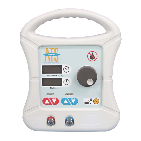
A.T.S. 1200 TOURNIQUET SYSTEM 3.10 REPLACEMENT PARTS The following is a list of field replacement parts that can be ordered from Zimmer. To obtain parts or additional information regarding your unit, write or phone: MAIL: Zimmer Orthopaedic Surgical Products 200 West Ohio Avenue Dover, Ohio 44622 U.S.A. - Page 25 A) Carrying Handle J) SECOND CUFF INFLATE/DEFLATE B) PRESSURE ADJUST Activation Buttons Buttons C) ALARM SILENCE Button K) Second Cuff Port D) Red ALARM Indicator L) Main Cuff Port E) TIME/PRESSURE Adjustment Knob M) MAIN CUFF INFLATE/DEFLATE Buttons F) TIME ADJUST Activation Button N) MAIN CUFF INFLATION Indicator G) ON/STANDBY Button O) SECOND CUFF INFLATION Indicator...
- Page 26 R) Power Cord S) Cord Retaining Clip T) Factory Test Port U) Pole Clamp V) Mains Fuse Block...
- Page 27 W) Calibrated Pressure Meter with a range of 0 to 500 mm Hg X) Pressure Regulator/Source adjustable from 0 to 500 mm Hg Y) Calibration Hose Included with Unit...
- Page 28 Opening the front case Removing the front case 1) Remove 3 screws on top, 2 at side and 2 feet on bottom. 1) Carefully slide the front off the rear. Disconnecting the wiring Removing the rear case 1) Use caution when disconnecting the wiring. Mark the wires before disconnecting or see 1) Remove 2 pole clamp screws on rear and Section 3.2 for proper re-connect.
- Page 29 Rear Case separation 1) All components are easily accessed when the rear case is removed. Reverse the process to reassemble. Be extremely careful not to pinch any wiring or tubing when reassembling!
- Page 30 Control Board Layout...
-
Page 31: Warnings, Cautions, And Symbol Definitions
Presence of this label on the product means it must not be disposed of in normal household waste and must be disposed of separately. To find out how to properly dispose of this product, please contact your local Zimmer Representative. - Page 33 SCHEMATICS...
- Page 34 Revised: 04-06 Zimmer Orthopaedic Surgical Products ©2002, 2006 Zimmer Orthopaedic Surgical Products, Inc. 200 West Ohio Avenue Printed in U.S.A. P.O. Box 10 0123 62-8000-015-00 ENG Dover, Ohio 44622 U.S.A.
Need help?
Do you have a question about the A.T.S. 1200 and is the answer not in the manual?
Questions and answers
How do I order the cables