Table of Contents
Advertisement
Advertisement
Table of Contents

Related Manuals for Zimmer A.T.S. 4000TS


Summary of Contents for Zimmer A.T.S. 4000TS
- Page 1 ENGLISH ® A.T.S. 4000TS Operator / Service Manual REF 60-4000-101-00...
- Page 2 Zimmer, Inc. warrants the Product (A.T.S. 4000TS Tourniquet System) for one year from date of purchase. During the warranty period, Zimmer will repair or replace, at its option, any product which is defective in materials or workmanship or which fails to meet the published specifi cation for that model. This Limited Warranty is made only to the original purchaser of the product and is non-transferable.
- Page 3 CONTENTS TABLE OF CONTENTS GENERAL INFORMATION ............... 4 INTENDED USE ........................4 CONTRAINDICATIONS .......................4 PRECAUTIONS IN USE .......................5 ADVERSE EFFECTS ......................6 SPECIFICATIONS AND PERFORMANCE CHARACTERISTICS ........6 ES 60601-1 CLASSIFICATION ....................8 EMISSIONS/IMMUNITY .......................8 INSTALLATION AND OPERATING INSTRUCTIONS ......9 INITIAL VISUAL INSPECTION ....................9 FEATURES AND OPERATING PRINCIPLES ..............9 BUTTONS AND ICONS ..........................
- Page 4 CONTENTS MAINTENANCE ................52 GENERAL MAINTENANCE INFORMATION..............52 LOP SENSOR CLEANING AND DISINFECTING .............52 PERIODIC MAINTENANCE ....................52 SERVICING ........................53 SERVICE MENU ACCESS ........................CALIBRATION ............................ATS LEAK TESTING ..........................UNIT INFORMATION ACCESS ....................... BURN MODE ............................TOUCH TEST ............................PROTECTIVE EARTH RESISTANCE TESTING ..................EARTH (EQUIPMENT) LEAKAGE CURRENT TESTING ...............
- Page 5 GENERAL INFORMATION APPLICATION SPECIFICATION The application specifi cation for the A.T.S. 4000TS including characteristics related to the use of the device, intended use, intended patient population, intended part of the body, intended user profi le, intended conditions of use and operating principles is contained in this manual.
- Page 6 110 kPa or the partial pressure of oxygen is greater than 27.5 kPa at ambient pressures exceeding 110 kPa. • Normal operation has the A.T.S. 4000TS running on ~ AC Power Mains via its power cord. The backup battery is intended for emergency power or transport.
- Page 7 GENERAL INFORMATION • Whenever the Tourniquet cuff pressure is released, the wound should be protected from blood surging back by applying pressure dressings and, if necessary, elevating the limb. Transient pain upon Tourniquet pressure release can be lessened by elevation of the limb. If full color does not return within 3 to 4 minutes after release, the limb should be placed in a position slightly below body level.
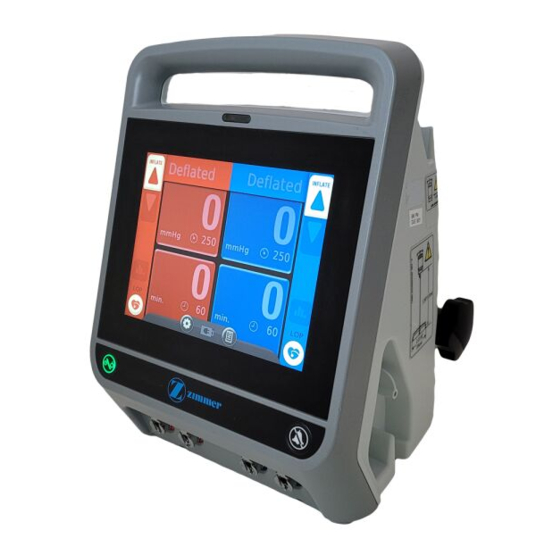
- Page 8 10.5 in. (26.7 cm) (including clamp). Weight: 13.2 lbs. (6.0 Kg) (including power cord). Displays The A.T.S. 4000TS uses an 8.4” SVGA LED backlit LCD panel. Pressure Display: Displays pressure setting, sensed cuff pressure, and other messages. Time Display: Displays time alarm set-point and elapsed time.
- Page 9 *When the unit is operating on backup battery, the type of protection against electric shock changes to internally powered equipment. EMISSIONS/IMMUNITY The A.T.S. 4000TS Tourniquet System complies with EMC criteria set forth in IEC 60601-1-2. The user of this device should be aware that precautions should be taken in regards to EMC. The device should be installed and used according to the EMC information provided in the instructions for use.
- Page 10 INSTALLATION AND OPERATING INSTRUCTIONS INITIAL VISUAL INSPECTION Unpack the A.T.S. 4000TS Tourniquet upon receipt and inspect the unit for any obvious damage that may have occurred during shipment including damage to any accessories. We recommend that this inspection be performed by a qualifi...
- Page 11 INSTALLATION AND OPERATING INSTRUCTIONS Button/Icon Title What it means Brightness Icon Appears in the system Settings when adjusting the backlight brightness. LOP Button Controls the Limb Occlusion Pressure (LOP) feature. When the pulse sensor is in place and cuff applied, pressing this button will start the process to measure the patient’s LOP and give the user a recommended Tourniquet pressure (RTP).
- Page 12 INSTALLATION AND OPERATING INSTRUCTIONS Button/Icon Title What it means Consult Manual Icon Indicates that the user should consult the operating instructions for complete instructions. Calibration Icon Represents the calibration functions. Language Icon Appears in the system Settings when changing the Primary System Language.
- Page 13 This button will not set the unit to STANDBY when the cuff pressure is at a non-zero value. • During STANDBY, the power to the A.T.S. 4000TS instrument and all instrument functions (i.e. infl ation, defl ation, etc.) are OFF but power continues to supply the battery charging circuitry anytime ~ AC Power Mains is present.
- Page 14 I.V. Pole with a base less than ≥27.56 inches (70 cm) in diameter. Hose Hangers The A.T.S. 4000TS is equipped with hose hangers at the back of its case. The cuff hoses can be temporarily hung on the hangers for transport or when disconnecting from the cuff.
- Page 15 TOUCH SCREEN GUI The A.T.S. 4000TS Graphical User Interface (GUI) consists of RED Main Cuff displays and controls on the left side and otherwise identical BLUE Second Cuff displays and controls on the right side. Additionally, GRAY general System functions are located on the bottom center of the screen.
- Page 16 Mains with protective earth. The A.T.S. 4000TS should be plugged into ~ AC Power Mains for 10 hours before initial setup to ensure the backup battery is fully charged. During shipping and storage, the unit’s battery could become weak. Always charge the system 10 hours before initial setup, including calibration checking procedures, initial checks, tests and any institution- performed biomedical evaluations.
- Page 17 “CALIBRATION OKAY” replaces the previous text and icon. CAUTION: The A.T.S. 4000TS will automatically perform an internal Diagnostic and Calibration check when powered ON. Setting the system to STANDBY and powering back ON between cases will allow the system to re-perform the automatic Diagnostic and Calibration check.
- Page 18 WARNING: • When medically necessary to use the A.T.S. 4000TS in the EXTENDED PRESSURE MODE, ensure the attached tourniquet cuff and hoses are capable of withstanding the extended pressure. Consult the cuff instructions for cuff pressure limits. Cuffs that have no specifi cations regarding pressure limits should not be used with high tourniquet pressures.
- Page 19 INSTALLATION AND OPERATING INSTRUCTIONS • The main TIME display should read “60” (the factory default set-point). The tile will automatically close in approximately 5 seconds. • Within the 5 second time frame, touch the negative left-arrow button to decrease or positive right-arrow button + to increase the TIME set-point.
- Page 20 INSTALLATION AND OPERATING INSTRUCTIONS • Create a leak in the cuff by partially detaching the hose (either port) from the unit while a cuff is infl ated. • Make the leak large enough that the pressure drops more than 15 mmHg below set-point. Observe: ■...
- Page 21 INSTALLATION AND OPERATING INSTRUCTIONS • Defl ate the cuff by TOUCH, SLIDE and HOLDING the DEFLATE (DEFL) button until defl ation begins: • Once the cuff fully defl ates, the Stats button appears on the Main Cuff Controls: Page 20...
- Page 22 INSTALLATION AND OPERATING INSTRUCTIONS • Touch the Stats button to reveal and review statistics of the previous pressure cycle: ■ The Pressure icon with right arrow FROM vertical bar indicates the start pressure. ■ The Pressure icon with right arrow TO vertical bar indicates the ending pressure if the pressure was adjusted during the procedure.
- Page 23 INSTALLATION AND OPERATING INSTRUCTIONS CAUTION: • If Advanced Leak Detection detected an excessive cuff leak during the infl ation period, the system will indicate “LEAK DETECTED.” • Resetting the Stats also resets the cuff timer. • After approximately 5 seconds of inactivity the system will automatically close open menus and return to its normal mode of operation.
- Page 24 The Volume can be changed to accommodate different environmental conditions so that the audio alarm can be reliably detected without being too intrusive in most situations. The A.T.S. 4000TS has nine Volume levels ranging from approximately 50 dB to 70 dB when measured at 1 meter from the center of the touch screen. To change the speaker...
- Page 25 INSTALLATION AND OPERATING INSTRUCTIONS Touch the Volume button. The Volume menu appears: - to decrease, or positive right-arrow button + Touch the negative left-arrow button to increase, the Alarm Volume. • Increments or decrements immediately take place and are automatically accepted and saved. •...
- Page 26 INSTALLATION AND OPERATING INSTRUCTIONS LANGUAGE SETTING To change the displayed Language, enter the Preferences menu and perform the following steps: Touch the Language button. The Language menu appears: Touch the up and down arrows to scroll to the preferred Language. Select the desired language and touch the Okay button to accept and save the new Language setting.
- Page 27 INSTALLATION AND OPERATING INSTRUCTIONS Press the Next button to begin the Cuff test. A testing view appears showing an animated progress bar and button: If desired, touch the Cancel button at any time to cancel the Cuff test. A passing test shows the following view: Touch the Cancel button to return to the Settings menu.
- Page 28 The A.T.S. 4000TS has the ability to determine the minimum effective pressure, called the Limb Occlusion Pressure (LOP). Once the A.T.S. 4000TS has determined the LOP, it provides a Recommended Tourniquet Pressure (RTP) that allows for anticipated changes in blood pressure during the procedure.
- Page 29 INSTALLATION AND OPERATING INSTRUCTIONS SURGEON DECISIONS The surgeon’s discretion will be used to determine the following: • What pressure to apply Refer to PRESSURE set-point system test under the Manual Tests and Checks section for how to set the target pressure set-point. For each patient, the surgeon determines if the Tourniquet pressure required to occlude blood fl...
- Page 30 RECOMMENDED TOURNIQUET PRESSURE (RTP) The A.T.S. 4000TS will take into account anticipated changes in blood pressure during the procedure by adding an additional pressure margin to the LOP value at the end of the LOP determination. This modifi ed pressure is referred to...
- Page 31 To improve visual quality, the RTP may be overridden at any time by changing the pressure set-point. The A.T.S. 4000TS will suggest the RTP for the extremity to ensure the fi eld will remain clear even during changes in blood pressure. However, large changes in the patient’s blood pressure during surgery may result in reduced visibility in the fi...
- Page 32 INSTALLATION AND OPERATING INSTRUCTIONS LOP MEASUREMENT This section covers how to operate the A.T.S. 4000TS to measure Limb Occlusion Pressure (LOP). Included are Single-Bladder Cuff LOP Measurement and Dual-Bladder Cuff LOP Measurement. SINGLE-BLADDER CUFF LOP MEASUREMENT To measure LOP with a Single Bladder Cuff, perform the following steps.
- Page 33 INSTALLATION AND OPERATING INSTRUCTIONS Touch the corresponding LOP button to start the LOP determination: The A.T.S. 4000TS evaluates the pulse signal quality during the beginning of the LOP feature: Page 32...
- Page 34 Touch the Cancel button again to exit the LOP function. The A.T.S. 4000TS begins to infl ate the cuff incrementally while continuously evaluating the patient’s pulse: • The LOP determination will last approximately 30 seconds depending on the quality of the pulse signal and patient’s physiological characteristics.
- Page 35 Touch the Cancel button again to exit the LOP function. At the end of the LOP determination, the A.T.S. 4000TS will defl ate the cuff and display the LOP and RTP pressures. To accept the RTP, touch the Next button .
- Page 36 ON. The unit will execute a diagnostic and calibration self-check test. After successful completion of the self-check test, the A.T.S. 4000TS unit is ready for use. The default settings for cuff pressure and time limit are retrieved during power-up. CAUTION: If a connected cuff is pressurized to 50 mmHg or more during power-up, the A.T.S.
- Page 37 Apply a leak-free dual-port Tourniquet cuff smoothly without wrinkles. • Apply a Zimmer protective sleeve or other padding to the limb. • Position the Tourniquet cuff so that its distal edge is located approximately 1 in. (2.5 cm) from the proximal edge of the exsanguinating bandage.
- Page 38 INSTALLATION AND OPERATING INSTRUCTIONS Remove the exsanguinating bandage. Administer the anesthetic agent or nerve block if regional anesthesia is being used. Perform the surgical procedure. At the end of the procedure, defl ate cuff by TOUCH, SLIDE and HOLDING the DEFLATE (DEFL) button until defl...
- Page 39 INSTALLATION AND OPERATING INSTRUCTIONS • Touch the Stats button to reveal and review statistics of the previous pressure cycle: ■ The Pressure icon with right arrow FROM vertical bar indicates the start pressure. ■ The Pressure icon with right arrow TO vertical bar indicates the ending pressure if the pressure was adjusted during the procedure.
- Page 40 Stats. • During normal use, the A.T.S. 4000TS should not be set to STANDBY if pressure is present in either cuff. Once the cuff has been properly defl ated, removed from the patient, and disconnected from the A.T.S. 4000TS, the unit can be set to STANDBY.
- Page 41 ALARM CONDITIONS There are a number of conditions for which the A.T.S. 4000TS Tourniquet will produce a visual and/or audible alarm. The appropriate actions indicated are based on the most probable causes and should only be used as a guide. Other causes of alarm conditions may indicate a need for other actions.
- Page 42 fi ttings should be checked for leaks. ADVANCED LEAK DETECTION The A.T.S. 4000TS has an Advanced Leak Detection feature that automatically monitors an infl ated cuff in real-time and observes potential leaks that may be occurring in the cuff or hoses. Advanced Leak Detection determines the magnitude of the leak.
- Page 43 ALARM/WARNING COLORS AND AUDIBLE TONES During the course of operation, the A.T.S. 4000TS may display a fl ashing red or yellow light and yellow warning tiles containing Alarm Condition messages. For a technical failure, it will also display warning messages accompanied by Error Codes and a yellow exclamation point graphic.
- Page 44 INSTALLATION AND OPERATING INSTRUCTIONS Warning Indicator Priority Condition, Remarks and Appropriate Action Message Light Tone BATTERY IS LOW Constant Condition: Battery is low (low). Yellow Battery charge is below 30% capacity. Plug unit into ~ AC Power Mains. If the unit is not plugged in, a battery fail condition will occur and the unit will shut down in a fail safe mode closing all cuff valves.
- Page 45 INSTALLATION AND OPERATING INSTRUCTIONS Warning Indicator Priority Condition, Remarks and Appropriate Action Message Light Tone TIMED OUT Constant Condition: LOP determination timed out. Yellow LOP determination is taking too long. Check LOP pulse sensor and retry. Replace LOP pulse sensor with known good working sensor and retry. If problem persists, service the unit.
- Page 46 Constant Red Technical Condition: Battery failed/error. ERROR Failure Specifi cation: The unit has detected a non-Zimmer battery was installed DETECTED Constant tone or the battery is no longer responding to commands. The unit has shut down in a safe state.
- Page 47 DETECTED Constant tone indicated the battery has failed. The unit has shut down in a safe state. Explanation/Action: Replace the battery with a new Zimmer battery pack. Cycle the ON/STANDBY button. If problem persists, note error code and contact manufacturer.
- Page 48 INSTALLATION AND OPERATING INSTRUCTIONS Error Code Warning Indicator Priority Explanation / Appropriate Actions Message Light Tone E0030 XXXX SYSTEM Constant Red Technical Condition: Amplifi er pneumatic voltage failure detected. FAILURE Failure Specifi cation: The unit has detected a low voltage failure in the DETECTED Constant tone pneumatic voltage supply.
- Page 49 Guidance and manufacturer’s declaration – electromagnetic emissions. The A.T.S. 4000TS is intended for use in the electromagnetic environments specifi ed below. The customer or the user of the A.T.S. 4000TS should assure that it is used in such an environment.
- Page 50 Guidance and manufacturer’s declaration – electromagnetic immunity The A.T.S. 4000TS is intended for use in the electromagnetic environments specifi ed below. The customer or the user of the A.T.S. 4000TS should assure that it is used in such an environment.
- Page 51 Guidance and manufacturer’s declaration – electromagnetic immunity. The A.T.S. 4000TS is intended for use in the electromagnetic environments specifi ed below. The customer or the user of the A.T.S. 4000TS should assure that it is used in such an environment.
- Page 52 A.T.S. 4000TS The A.T.S. 4000TS is intended for use in the electromagnetic environment in which radiated RF disturbances are controlled. The customer or the user of the A.T.S. 4000TS can help prevent electromagnetic interference by maintaining a minimum distance between portable and mobile RF communications equipment (transmitters) and the A.T.S.
- Page 53 Clean or disinfect the Limb Occlusion Pressure (LOP) sensor before attaching to a new patient. Cleaning Unplug the LOP sensor from the A.T.S. 4000TS Tourniquet before cleaning. Clean the sensor and patient contact surfaces with a soft cloth dampened (not dripping) in water or a mild detergent solution.
- Page 54 CALIBRATION Calibration of the A.T.S. 4000TS Tourniquet allows the output signal from the pressure transducers to be compared against a calibrated pressure source. The difference between the known pressure and the pressure measured by the transducers is recorded at each of fi...
- Page 55 Routes air pressure between a regulated pressure supply to a pressure meter and the A.T.S. 4000TS unit’s cuff ports. (Provided) The Calibration Hose Kit is supplied by Zimmer and included with the unit. CAUTION: The clamp on the calibration hose remains opened (not clamped) during calibration.
- Page 56 MAINTENANCE CUFF AND RESERVOIR CALIBRATION Below is a step-by-step procedure for calibrating both cuff transducers as well as the reservoir transducer. The calibration procedure will not be complete until both cuff transducers and the reservoir transducer are calibrated in the exact sequence below: •...
- Page 57 MAINTENANCE • The system will be looking for 250 mmHg to be applied to the cuff pressure transducers. The pinwheel will be rotating at the 250 numerical value waiting for the pressure to be applied. Once the pressure has been applied and is stable, touch the -250- button to calibrate the cuff transducers at the 250 mmHg point.
- Page 58 MAINTENANCE CAUTION: During the calibration of the reservoir transducer, the pressure in the cuff displays will not be active (0 mmHg) because these steps are for the internal reservoir transducer. Always use the external calibrated pressure meter’s display for the proper calibration value. •...
- Page 59 MAINTENANCE While the CALIBRATION ERROR message is being displayed, press and hold the Alarm Silence button. Continue to press the Alarm Silence button and then touch the yellow caution triangle on the screen. The system will continue to load and then automatically enter the calibration screen. Complete the calibration per the CUFF and RESERVOIR CALIBRATION section.
- Page 60 ATS LEAK TESTING The A.T.S. 4000TS Tourniquet is capable of maintaining the cuff pressure set-point with an internal or external leak. Naturally it is desirable to keep plumbing leaks to an absolute minimum. For this reason, a check for signifi cant leakage is recommended during the 6 month periodic maintenance interval as well as following any service procedure.
- Page 61 MAINTENANCE CAUTION: This test will check internal pneumatic connections inside the ATS machine. This test is not intended to check cuffs or external connections. A leaking external connection unrelated to the ATS machine will potentially cause this test to show a false leak. UNIT INFORMATION ACCESS The system contains an information block that will allow a qualifi...
- Page 62 If the system continues to fail the Touch Test, the system should be removed from service immediately along with all accessories and reported to the designated individual responsible for equipment repair within the healthcare organization. The system should be returned to Zimmer for repair. Page 61...
- Page 63 BACKUP BATTERY SERVICE The A.T.S. 4000TS System is equipped with a Lithium Ion backup battery. The battery is designed to last for years when properly maintained. The system has a built-in battery charger that maintains the battery power as long as ~ AC Power Mains is present.
- Page 64 Replace the battery with a new Zimmer battery when the battery health is depleted. CAUTION: The A.T.S. 4000TS System should be plugged in at least 10 hours before putting back into use to ensure a full battery charge in case of emergency power loss BATTERY-HANDLING RECOMMENDATIONS •...
- Page 65 Reconnect the power cord to power entry module, plug in to AC and verify device AC power is active. UNSCHEDULED MAINTENANCE The A.T.S. 4000TS Tourniquet is designed with several specifi c self-test features to assist in fault isolation. These features are designed to show messages in the display. The meanings of these messages are delineated in the ERROR CODES table.
- Page 66 MAINTENANCE TROUBLE SHOOTING GUIDE To aid in unscheduled maintenance, the TROUBLESHOOTING table delineates a number of possible malfunctions that could occur with the unit. The most likely causes are shown for each symptom. While it is not practical to enumerate every conceivable malfunction and all possible causes, the table will assist in isolating the most common problems.
- Page 67 CAUTION - HIGH VOLTAGE ELECTRICAL HAZARD: High voltage will be present on the power input module and control board. All service work must be completed by Zimmer or a qualifi ed biomedical engineer or other person thoroughly familiar with electronic medical devices within the healthcare organization.
- Page 68 MAINTENANCE 60401700100 Dual Cuff Hose Blue 604000096EN Operator & Service Manual, English 604000096DA Operator & Service Manual, Danish 604000096NL Operator & Service Manual, Dutch 604000096FI Operator & Service Manual, Finnish 604000096FR Operator & Service Manual, French 604000096DE Operator & Service Manual, German 604000096IT Operator &...
- Page 69 • Part Number (if known) CAUTION: We strongly recommend that all repairs be done by Zimmer or a qualifi ed biomedical engineer or other person thoroughly familiar with electronic medical devices within the healthcare organization. CONTACT INFORMATION To obtain part or additional information regarding your unit, contact your Zimmer distributor or write or phone:...
- Page 70 MAINTENANCE WARNINGS, CAUTIONS & SYMBOLOGY Below are graphical Warning, Caution and other Symbols indicated on the A.T.S. 4000TS system and within this manual. Graphic What it means The tourniquet system shall be placed no higher than 50 inches (127 cm) from the fl...
- Page 71 Presence of this label on the product means it must not be disposed of in normal household waste and must be disposed of separately. To fi nd out how to properly dispose of this product, please contact your local Zimmer Representative.
- Page 72 MAINTENANCE Graphic What it means Indicates hazards arising from dangerous voltages. Signifi es a general warning. Used to distinguish between identical or similar devices sold in both sterile and nonsterile conditions. Indicates authorized representative (REP) in the European Community (EC). Indicates catalog, reorder or reference number.
- Page 73 MAINTENANCE Graphic What it means Indicates manufacturer and is accompanied by the name and address of the manufacturer. Indicates date of manufacture and is accompanied by a date. YYYY-MM Indicates suitability for alternating current only. Indicates suitability for direct current only. Indicates equipment or systems in the medical electrical area that include RF transmitters or that intentionally apply RF electromagnetic energy for diagnosis or treatment.
- Page 74 Name of Testing Person: _______________________ Test after repair Responsible Organization: _________________________________________________________ Equipment: ___________________________ ID – Number: __________________________ Type: ________________________________ Serial Number: ________________________ Manufacturer: Zimmer Class of Protection: Class I Class II Battery Applied Part Type: Mains Connection: Permanently Installed Non-detachable Power Cord...
- Page 76 Zimmer Surgical, Inc. 200 West Ohio Avenue Dover, Ohio 44622 U.S.A. Revision: B Zimmer U.K. LTD. © 2013 Zimmer Surgical, Inc. 9 Lancaster Place Printed in U.S.A. South Marston Park 622400048EN Swindon, Wiltshire SN3 4FP United Kingdom 0086...
Need help?
Do you have a question about the A.T.S. 4000TS and is the answer not in the manual?
Questions and answers