
Related Manuals for Zimmer A.T.S. 3000


Summary of Contents for Zimmer A.T.S. 3000
- Page 1 Operator A.T.S. 3000 AUTOMATIC TOURNIQUET SYSTEM & Service Manual Zimmer A.T.S. 3000 ® AUTOMATIC TOURNIQUET SYSTEM REF 60-3000-101-00...
- Page 2 Zimmer, Inc. warrants the Product (A.T.S. 3000 Tourniquet System) for one year from date of purchase. During the warranty period, Zimmer will repair or replace, at its option, any product which is defective in materials or workmanship or which fails to meet the published specification for that model.
-
Page 3: Table Of Contents
A.T.S. 3000 AUTOMATIC TOURNIQUET SYSTEM ENGLISH TABLE CONTENTS ZIMMER A.T.S. 3000 AUTOMATIC TOURNIQUET SYSTEM SECTION TITLE PAGE GENERAL INFORMATION Specifications ............................Intended Use ............................Contraindications ..........................Precautions in Use ..........................Adverse Effects ............................ INSTALLATION AND OPERATING INSTRUCTIONS Initial Inspection .......................... - Page 4 Troubleshooting ........................... 29 Expected Test Point Readings ......................31 Parts List .............................. 32 ILLUSTRATIONS A.T.S. 3000 Overview – front ......................33 A.T.S. 3000 Overview – rear ....................... 34 Main and Second Calibration Kit Setup ....................35 Battery Removal Overview ......................... 35 Rear Power Cord Cover Removal .......................
-
Page 5: General Information
GENERAL INFORMATION A.T.S. 3000 AUTOMATIC TOURNIQUET SYSTEM SECTION 1.0 ZIMMER A.T.S. 3000 AUTOMATIC TOURNIQUET SYSTEM 1.1 SPECIFICATIONS PRESSURE Button: PRESSURE Mains Line Voltage Range: 100–240 V ~ (AC), 50/60 Hz. Auto switching Line Current: 670 mA RMS @ 120 V ~ (AC) - Page 6 Weight: 16.3 lbs. (7.4 kg) Alarm Indicator Light Icon (Red LED): DISPLAYS: The A.T.S. 3000 uses a backlit 1/4 panel LCD. Pressure Display: Displays pressure setting, sensed cuff pressure, and hardware failure conditions / other messages. Visual indicator to show the unit is in an alarm condition.
- Page 7 Emissions/Immunity: The A.T.S. 3000 Tourniquet System complies with EMC criteria set forth in EN 60601-1-2. The user of this device should be aware that precautions should be taken in regards to EMC. The device should be installed and used according to the EMC information provided in the instructions for use.
-
Page 8: Intended Use
1.2 INTENDED USE 1.4 PRECAUTIONS IN USE ◆ The tourniquet system must be kept well calibrated The A.T.S. 3000 Tourniquet System is intended to be used by and in operable condition. Accessories should be checked qualified medical professionals to temporarily occlude blood regularly for leaks and other defects. -
Page 9: Adverse Effects
A.T.S. 3000 AUTOMATIC TOURNIQUET SYSTEM pressure distribution on the limb. The skin under the 1.5 ADVERSE EFFECTS tourniquet cuff must be protected from mechanical injury by A dull aching pain (tourniquet pain) may develop throughout the limb following use. smooth, wrinkle-free application of the cuff. -
Page 10: Installation And Operating Instructions
If the unit is damaged, notify the carrier and your Zimmer approximately 2 seconds before the unit will allow a cuff representative immediately. If the initial inspection results to deflate. -
Page 11: Initial Setup
RED ports and the Second Cuff is the BLUE ports. a) “Zimmer” along with the circle “Z” appears on the The A.T.S. 3000 is designed and tested for use with LCD display. Zimmer dual port cuffs. Zimmer does not recommend b) The unit displays “SELF TEST”... - Page 12 A.T.S. 3000 AUTOMATIC TOURNIQUET SYSTEM A.T.S. 3000 AUTOMATIC TOURNIQUET SYSTEM 5. Calibration Check Increase the pressure to 475 mmHg. Both PRESSURE displays should read 475±5 mmHg. NOTE: During the power-up diagnostic self-test described Decrease the pressure to 0 mmHg and remove above, the unit will test the calibration.
-
Page 13: Pressure And Time Defaults
LOP determination. 1.5 seconds and the audible alarm will beep once The A.T.S. 3000 will suggest the RTP as the lowest pressure signifying a new default value has been stored. for the extremity to ensure the field will remain clear even e) The new time limit default will be stored and during changes in blood pressure. - Page 14 A.T.S. 3000’s pulse sensor does not measure oxygen positions are the upper arm and the proximal third saturation nor can it be modified to do so. The A.T.S. 3000 of the thigh. In certain cases of fore-foot surgery, the uses a custom sensor.
-
Page 15: Single Cuff Operation
RTP, turn the Shuttle Knob and follow f thru i. the procedure in Section 2.4.3.c to adjust the second NOTE: The A.T.S. 3000 will not automatically inflate the RTP to equal the first RTP. cuff at the end of the LOP determinations. It is the user’s If the RTP from the first LOP determination is responsibility to accept or reject the RTP. -
Page 16: Dual Cuff Operation
A.T.S. 3000. come up approximately to 1 in. (2.5 cm) from the edge During normal use, the A.T.S. 3000 should not be set to of the tourniquet cuff. The elastic bandage is removed STANDBY if pressure is present in either cuff. Once following inflation of the cuff. -
Page 17: Bier Block Cuff Operation (Ivra)
2.12 ALARM CONDITIONS deflation sequence adopted by your institution or requested by the surgeon. There are a number of conditions for which the A.T.S. 3000 Tourniquet will produce a visual and/or audible alarm. Those 2.10 SPEAKER VOLUME SETTING conditions, indications, and appropriate actions are shown An operator may want to change the speaker volume setting in Table 2.1. - Page 18 15 mmHg from the pressure set point. It is also The A.T.S. 3000 Tourniquet will also provide Error Code possible for a cuff to have a leak that is substantial but which information for critical alarms as shown in Table 2.3.
- Page 19 A.T.S. 3000 AUTOMATIC TOURNIQUET SYSTEM Table 2.1 Alarm Condition Continued CONDITION PRESSURE TIME APPROPRIATE ACTION/REMARKS DISPLAY DISPLAY LINE OCCLUSION LINE OCCL normal Check for hose kinks or other defects. An occlusion is present in the cuff tubing LOW BATTERY VOLTAGE...
-
Page 20: Error Codes
A.T.S. 3000 AUTOMATIC TOURNIQUET SYSTEM Table 2.2 LOP Alarm Condition CONDITION PRESSURE TIME APPROPRIATE ACTION/REMARKS DISPLAY DISPLAY No LOP pulse sensor detected Message displayed at bottom Plug LOP pulse sensor in. Reattach LOP pulse sensor and during LOP of display area. - Page 21 A.T.S. 3000 AUTOMATIC TOURNIQUET SYSTEM Table 2.3 Error Codes Continued ERROR CODE CRITICAL FAILURE EXPLANATION/APPROPRIATE ACTIONS A Safety Monitor detection error was detected. Cycle the ON/ E006 SYSTEM FAIL STANDBY button. If problem persists, note error code and contact manufacturer.
-
Page 22: Emc Guidance And Declaration - Emc Emissions
Table 2.4 EMC Guidance and Declaration - EMC Emissions Guidance and manufacturer’s declaration – electromagnetic emissions The A.T.S. 3000 is intended for use in the electromagnetic environments specified below. The customer or the user of the A.T.S. 3000 should assure that it is used in such an environment. - Page 23 IEC 61000-4-11 40% U T 40% U T The A.T.S. 3000 is equipped with a backup battery (60% dip in U T ) (60% dip in U T ) in the event of power mains interruptions. Consult...
- Page 24 To assess the electromagnetic environment due to fixed RF transmitters, an electromagnetic site survey should be considered. If the measured field strength in the location in which the A.T.S. 3000 is used exceeds the application RF compliance levels above, the A.T.S. 3000 should be observed to verify normal operation. If abnormal performance is observed, additional measures may be necessary, such as re-orienting or relocating the A.T.S.
-
Page 25: Emc Guidance And Declaration - Emc Immunity/Separation Distances
Recommended separation distances between portable and mobile RF communication equipment and the A.T.S. 3000 The A.T.S. 3000 is intended for use in the electromagnetic environment in which radiated RF disturbances are controlled. The customer or the user of the A.T.S. 3000 can help prevent electromagnetic interference by maintaining a minimum distance between portable and mobile RF communications equipment (transmitters) and the A.T.S. -
Page 26: Maintenance
3.1 GENERAL MAINTENANCE INFORMATION To reduce the risk of damage, tubing should not be disconnected at the transducer. While the A.T.S. 3000 Tourniquet has been designed and NOTE: Failure to plug the electrical or pneumatic manufactured to high industry standards, it is recommended... -
Page 27: Calibration
Cuff sense ports. See Figure 3 for more details. after any unscheduled maintenance. The Main Cuff sense port is the second port over Calibration of the A.T.S. 3000 Tourniquet allows the output from the left side of the unit. signal from the pressure transducers to be compared against b. -
Page 28: Leak Testing
3.6 LEAK TESTING 475 mmHg of pressure. Once the pressure has stabilized, The A.T.S. 3000 Tourniquet is capable of keeping a cuff with press the Main Cuff PRESSURE button so the unit can a substantial leak inflated. Naturally it is desirable to keep calibrate the 475 mmHg point. -
Page 29: Battery Voltage And Battery Service
A.T.S. 3000 AUTOMATIC TOURNIQUET SYSTEM NOTE: During the 10 seconds, the alarm message will be battery in the A.T.S. 3000 Tourniquet System be replaced displayed, the alarm will continue to sound and the ALARM annually. As a reminder, the A.T.S. 3000 System should SILENCE button will not silence the alarm. -
Page 30: Unscheduled Maintenance
AC and verify device AC power is active. 3.9 UNSCHEDULED MAINTENANCE The A.T.S. 3000 Tourniquet is designed with several specific self-test features to assist in fault isolation. These features are designed to show messages in the Pressure and Time displays. -
Page 31: Troubleshooting
A.T.S. 3000 AUTOMATIC TOURNIQUET SYSTEM Table 3.2 Troubleshooting SYMPTOM POSSIBLE CAUSES a) Membrane Panel not properly plugged into P8. b) Tubing inside unit may be pinched or improperly connected. c) Deflate valve is stuck open. 1. Main Cuff or Second Cuff will not inflate. - Page 32 A.T.S. 3000 AUTOMATIC TOURNIQUET SYSTEM Table 3.2 Troubleshooting SYMPTOM POSSIBLE CAUSES a) Transducer amplifier not working. 7. No cuff pressure reading. b) Internal tubing kinked. c) Transducer tubing on incorrect transducer. a) Leak in internal hose or connector. b) Internal tubing kinked.
-
Page 33: Expected Test Point Readings
A.T.S. 3000 AUTOMATIC TOURNIQUET SYSTEM Table 3.3 Expected Test point Readings Board Location Nominal-Reading Tolerance Description / Comments 5.0 Vdc +0.2 5 Volt DC supply for battery charge circuit 0.0 Vdc 0 Vdc while on battery operation 26.9 Vdc +1.5... -
Page 34: Replacement Parts
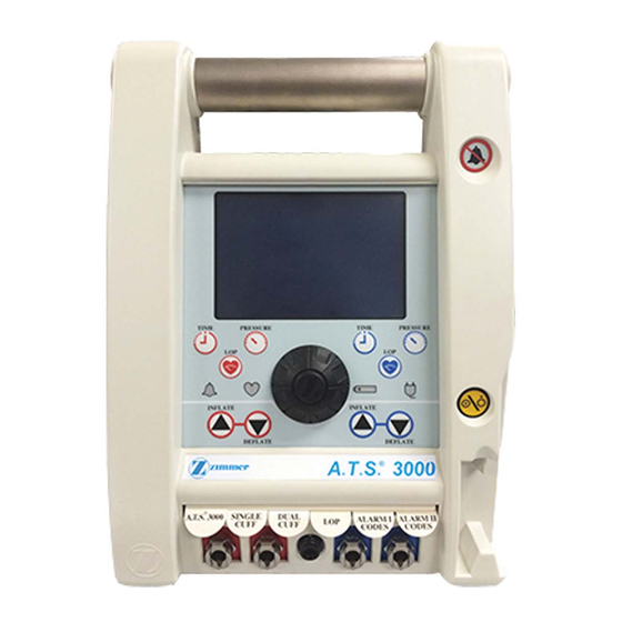
A.T.S. 3000 AUTOMATIC TOURNIQUET SYSTEM 3.12 REPLACEMENT PARTS The following is a list of field replacement parts that can be ordered from Zimmer. To obtain part or additional information regarding your unit, write or phone: MAIL Zimmer Surgical 200 West Ohio Avenue Dover, Ohio 44622 U.S.A. - Page 35 A.T.S. 3000 AUTOMATIC TOURNIQUET SYSTEM FRONT CASE VIEW 1. Carrying Handle 14. LOP Port Socket 2. ALARM SILENCE Button 15. Main Cuff Ports 3. Display Window 16. Quick Reference Cards 4. Second Cuff TIME Button 17. Main Cuff DEFLATE Button 5.
- Page 36 A.T.S. 3000 AUTOMATIC TOURNIQUET SYSTEM REAR CASE VIEW 1. Power Cord 5. Pole Clamp 2. Cord / Pole & Clamp Cover 6. Mains Fuse Block 3. Potential Equalization Conductor Stud 7. Rear Case and Handle Screws 4. Factory Test Port...
-
Page 37: Main And Second Calibration Kit Setup
A.T.S. 3000 AUTOMATIC TOURNIQUET SYSTEM TO SECOND CUFF PORT TO MAIN CUFF PORT Main and Second Calibration Kit Setup 1. Calibrated Pressure Meter with a minimum range of 0 to 700 mmHg. 2. Pressure Regulator / Source adjustable from 0 to 700 mmHg minimum. - Page 38 A.T.S. 3000 AUTOMATIC TOURNIQUET SYSTEM Removing the Battery Continued Removing the Rear Power Cord Clamp Cover 3) Disconnect battery at the cord plug connection. 1) Remove the 4 #6 nuts holding the Cord / Pole Clamp 4) Replace battery by removing Battery Clamp.
-
Page 39: Rear Case Separation
A.T.S. 3000 AUTOMATIC TOURNIQUET SYSTEM Rear case separation 1) All components are easily accessed when the rear case is removed. 2) Remove the Cord / Pole Clamp Cover and Pole Clamp before proceeding. See illustrations 5 and 6. 3) Remove the power cord from the back of the unit. -
Page 40: Control Board Layout
A.T.S. 3000 AUTOMATIC TOURNIQUET SYSTEM Control Board Layout 1. LCD Panel Header (P5) 9. Battery Fuse (F1) 2. Main Cuff Valve Header (P7) 10. Second Cuff Valve Header (P6) 3. Factory Test Port Header (P12) 11. ON / STANDBY Header (P11) 4. -
Page 41: Warnings, Cautions, And Symbology
A.T.S. 3000 AUTOMATIC TOURNIQUET SYSTEM 3.14 Warnings, Cautions, and Symbology YYYY-MM h P d Contains or presence of Phthalates. Replace fuse as marked CAUTION: Federal law (USA) This product contains a Lead Acid restricts this device to sale by or on Battery that must be recycled. - Page 44 A.T.S. 3000 AUTOMATIC TOURNIQUET SYSTEM Zimmer Surgical, Inc. 200 West Ohio Avenue Dover, Ohio 44622 U.S.A. Revision: 12-10 Zimmer U.K. LTD. © 2005, 2010 Zimmer Surgical, Inc. 9 Lancaster Place Printed in U.S.A. South Marston Park 62210009600 ENG Swindon, Wiltshire SN3 4FP...
Need help?
Do you have a question about the A.T.S. 3000 and is the answer not in the manual?
Questions and answers
Comming amp fail
A "AMP FAIL" error on the Zimmer A.T.S. 3000 indicates that a voltage level is out of range. If the error persists after cycling the ON/STANDBY button, the error code should be noted, and the manufacturer should be contacted for further assistance.
This answer is automatically generated
Over pressure indication on display