
Subscribe to Our Youtube Channel
Related Manuals for Ametek Land SDS


Summary of Contents for Ametek Land SDS
- Page 1 INSTALLATION GUIDE PUBLICATION N 813663 LANGUAGE: ENGLISH ISSUE: 2 DATE: 06 NOVEMBER 2019 Slag Detection System Q U A L I T Y C U S T O M E R S O L U T I O N S...
- Page 2 Observe precautions for handling electrostatic discharge sensitive devices. Equipment Operation Use of this instrument in a manner not specified by AMETEK Land may be hazardous. Read and understand the user documentation supplied before installing and operating the equipment. The safety of any system incorporating this equipment is the responsibility of the assembler.
- Page 3 This manual is provided as an aid to owners of AMETEK Land’s products and contains information proprietary to AMETEK Land. This manual may not, in whole or part, be copied, or reproduced without the expressed written consent of AMETEK Land.
-
Page 4: Table Of Contents
Slag Detection System Contents Introduction About SDS System Overview System Components SDS Camera PSU Module Air Blower Process Imaging Workstation IO Module Camera Location System Interconnections Cooling Water Connections Purge Air Connections Power & Signal Connections Workstation Network Connections Software Installation Maintenance Spare Parts Appendix - Conduit Instructions... -
Page 5: Introduction
INTRODUCTION This Installation Guide gives you information on how to install and set up the AMETEK Land Slag Detection System (SDS) 1.1 About SDS The AMETEK Land Slag Detection System (SDS) comprises: • SDS-640 Thermal Imaging Camera • UL Approved Power Supply Unit •... -
Page 6: System Overview
Slag Detection System SYSTEM OVERVIEW Fig. 2-1 SDS System Overview 2 - 0 Installation Guide... -
Page 7: System Components
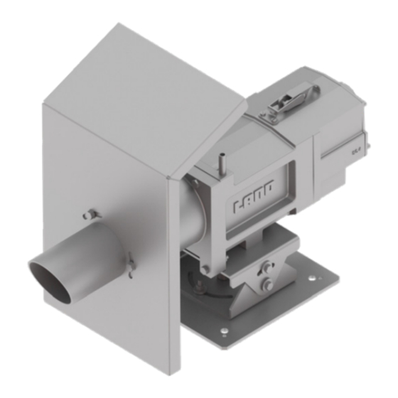
Slag Detection System SYSTEM COMPONENTS 3.1 SDS Camera Components • SDS-640 Camera • SDS-640 Pan & Tilt Assembly • SDS-640 Protection Plate • Air Purge, Water Jacket & Back Cap Fig. 3-1 SDS Camera Specifications Measurement Range 800 to 1800 °C / 1472 to 3271 °F Image Resolution 640 x 480 pixels Field of View... - Page 8 Slag Detection System 3 - 2 Installation Guide...
-
Page 9: Psu Module
Slag Detection System 3.2 PSU Module Features • Interface between SDS Camera and Image Processing Workstation • UL Approved Fig. 3-3 SDS Power Supply Unit (PSU) Module Specifications Refer to the SDS PSU (UL Approved) Installation Guide, Publication Nº 813482. Connections AC Mains Power In Power &... -
Page 10: Air Blower
3.3 Air Blower Features • Provides constant regulated air supply for SDS Camera purge Fig. 3-5 AMETEK Land Plate Mounted Blower Specifications Refer to the Plate Mounted Blower Installation Guide, Publication Nº 770-073. Weight 21.5 kg / 47.3 lb without cover 32.8 kg / 72.2 lb with cover... - Page 11 Slag Detection System Installation Guide 3 - 5...
-
Page 12: Process Imaging Workstation
Slag Detection System 3.4 Process Imaging Workstation Features • SDS Server Software Fig. 3-7 SDS Process Imaging Workstation Specifications Connections AC Mains Power In Ethernet Communications to SDS PSU Module and MOXA I/O Temperature range Operating 0 to 35 °C (32 to 95 °F) Storage -40 to 65 °C (-40 to 149 °F) Relative humidity (maximum) 10 to 80 % (non-condensing) -
Page 13: Io Module
Slag Detection System 3.5 IO Module Features • DIN Rail Mounted • Must be installed inside an enclosure Fig. 3-8 IO Module & PSU (DIN Rail mounted) Specifications - IO Module Mountings DIN Rail Connections AC Mains Power In Ethernet to Process Imaging Workstation Breakdown Voltage 500 VAC Contact Current Rating Resistive load 5 A @ 30 VDC, 250 VAC, 110 VAC... -
Page 14: Camera Location
Slag Detection System CAMERA LOCATION WARNING Do not attempt to install the SDS Camera when molten metal is being poured in the vicinity. Camera location • Refer to Figs. 4-1 and 4-2 • Make sure that the SDS Camera has an unobstructed view of the target •... - Page 15 Slag Detection System Distance Distance 13.1 ft Width Height IFOV Width Height IFOV 0.84 m 0.63 m 1.3 mm 33.1 in 24.8 in 0.05 in Distance Distance 16.4 ft Width Height IFOV Width Height IFOV 1.05 m 0.78 m 1.6 mm 41.3 in 30.7 in 0.06 in...
-
Page 16: System Interconnections
Slag Detection System SYSTEM INTERCONNECTIONS WARNING Do not attempt to install the SDS System when molten metal is being poured in the vicinity. Make sure that the cooling water supply for the SDS protective jacket is installed and operating correctly before using the SDS in its chosen measurement location. -
Page 17: Cooling Water Connections
Slag Detection System 5.1 Cooling Water Connections Water Hoses (Customer supplied) • Always use flexible hose to allow for pan & tilt • Hose internal diameter: 10 mm / 0.39 in • Secure to inlet and outlet connectors on SDS jacket with suitable clips Cooling Water •... -
Page 18: Purge Air Connections
• Hose internal diameter: 38 mm / 1.5 in • Secure to SDS Jacket inlet and Blower outlet connectors with clips supplied AMETEK Land Air Blower • Maximum ambient temperature: 50 °C / 132 °F • Use only in locations where the incoming air is not corrosive, inflammable or explosive. -
Page 19: Power & Signal Connections
Slag Detection System 5.3 Power & Signal Connections Air & Water Supplies Power Supply Unit (UL Approved) Cable Conduit • 10 m / 30 ft Conduit (UL Approved) Part Nº 813515 • Straight M32 Male Fitting Conduit (UL Approved) Part Nº 813516 •... -
Page 20: Workstation Network Connections
Slag Detection System 5.4 Workstation Network Connections IO Module • AMETEK Land Part Nº 813660 • Moxa I/O E1214 6DI & 6 Relay Out (24 V, 188 mA) • 24 V PSU e.g. Phoenix Contact UNO-PS/1AC/24DC/30W UL/cUL • DIN Rail Mounting • Must be fitted inside closure to... -
Page 21: Software Installation
Slag Detection System SOFTWARE INSTALLATION Refer to the IMAGEPro-SDS Software User Guide and Online Help. Installation Guide 6 - 1... -
Page 22: Maintenance
Slag Detection System MAINTENANCE It is recommended that the following are checked on a regular basis. • Check for loose wiring or any other damage to cables and/or conduits • Check that the cooling water supply is within the recommended temperature and flow rate limits •... -
Page 23: Spare Parts
Slag Detection System SPARE PARTS Part Number Description 813451 SDS 640 System 813216 SDS-640 Camera 813472 SDS 640 Pan & Tilt Assembly 813477 SDS 640 Back Cap Assembly 813666 SDS 640 Spare Protection Plate 813478 SDS-640 PSU Module (UL) 813524 SDS-640 Air Purge Assembly 813517 SDS 640 Rugged Enclosure... -
Page 24: Appendix Conduit Instructions
Slag Detection System APPENDIX CONDUIT INSTRUCTIONS Appendix Installation Guide... - Page 26 Slag Detection System...
- Page 27 Slag Detection System...
- Page 28 Email: land.enquiry@ametek.com www.ametek-land.com www.ametek-land.com For a full list of international offices, please visit our website www.ametek-land.com Copyright © 2019 LAND Instruments International. Continuous product development may make it necessary to change these details without notice. SDS Slag Detection System Installation Guide, Issue 2, 06 November 2019...
Need help?
Do you have a question about the Land SDS and is the answer not in the manual?
Questions and answers