Table of Contents
Advertisement
Advertisement
Table of Contents

Related Manuals for Ametek JOFRA CTC-140 A


Summary of Contents for Ametek JOFRA CTC-140 A
- Page 1 User manual Temperature Calibrator JOFRA CTC-140/320/650 A/B JOFRA CTC-1200 A...
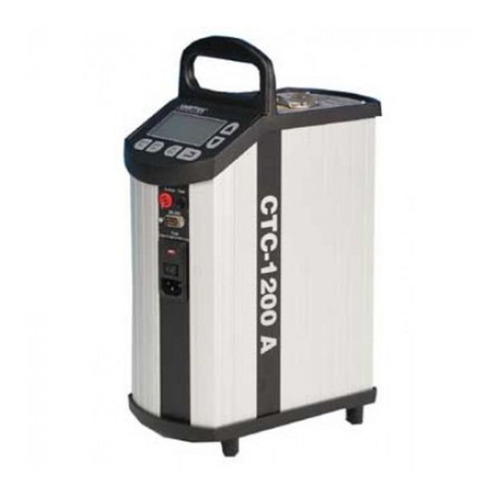
- Page 2 User manual Temperature Calibrator JOFRA CTC-140/320/650 A/B JOFRA CTC-1200 A Copyright 2005 AMETEK DENMARK A/S (123199-UK)
- Page 4 FIG. 1 Switch Test RS232 2013-10-10...
- Page 5 FIG. 2 CALIBRATION INSTRUMENTS SWITCH AUTO STEP TEST MENU ° ° ° ° 2013-10-10...
- Page 6 °C °C 2013-10-10...
- Page 7 2013-10-10...
- Page 8 2013-10-10...
- Page 9 2013-10-10...
-
Page 10: Table Of Contents
List of contents 1.0 Introduction..............2 1.1 List of equipment received..........2 2.0 Safety instructions ............3 3.0 Operating the calibrator ..........8 3.1 Before use................. 8 3.2 Keyboard................. 11 3.3 Display ................11 3.4 Connections ..............12 3.5 Calibrator functions - overview......... 12 3.6 Selecting the set-temperature.......... -
Page 11: Introduction
Introduction CTC-calibrators are temperature calibrators designed to calibrate temperature sensors and temperature switches. Read this manual carefully before using the instrument and make sure that all safety instructions and warnings are observed. List of equipment received When you receive the instrument, the following should be enclosed: ... -
Page 12: Safety Instructions
Safety instructions Read this manual carefully before using the instrument! In order to avoid any personal injuries and/or damage to the instrument all safety instructions and warnings must be observed. Disposal – WEEE Directive These calibrators contain Electrical and Electronic circuits and must be recycled or disposed of properly (in accordance with the WEEE Directive 2002/96/EC). - Page 13 To ensure the connection to protective earth any extension cord used must also have a protective earth conductor. Only use a mains power cord with a current rating as specified by the calibrator and which is approved for the voltage and plug configuration in your area.
- Page 14 Never place a hot insertion tube in the optional carrying case. Use only insulation plugs supplied by AMETEK Denmark A/S. Do not try to modify the insulation plugs to make them fit the sensor (CTC-1200 A only). About the fuses: ...
- Page 15 Caution – Cold surface Below 0°C/32°F (applies only to the CTC-140 A models) Do not touch the well or insertion tube when these are below 0°C/32°F - they might create frostbite. If the calibrator has reached a temperature below 0°C/32°F, ice crystals may form on the insertion tube and the well.
- Page 16 The humidity in the air may cause corrosion oxidation on the insertion tube inside the instrument. There is a risk that the insertion tube may get stuck if this is allowed to happen. If the calibrator is to be transported, the insertion tube must be removed from the well to avoid damage to the instrument.
-
Page 17: Operating The Calibrator
Operating the calibrator Before use Warning The calibrator must not be used for any purposes other than those described in this manual, as it might cause a hazard. The calibrator has been designed for indoor use only and is not to be used in wet locations. ... - Page 18 1 metre above the calibrator due to fire hazard. Use only insulation plugs supplied by AMETEK Denmark A/S. Do not try to modify the insulation plugs to make them fit the sensor (CTC-1200 A only).
- Page 19 Caution… The well and the insertion tube must be clean before use. The insertion tube must never be forced into the well. The well could be damaged as a result, and the insertion tube may get stuck. Do not pour any form of liquids into the well.
-
Page 20: Keyboard
Keyboard The keys on the keyboard activate the following functions (cf. fig. 2): Description UP ARROW button used to adjust temperature values (value increases) and to select menu options. DOWN ARROW button used to adjust temperature values (value decreases) and to select menu options. ENTER button used to accept chosen options. -
Page 21: Connections
Used to display set-temperature, time-until-stable and parameter values in the menu system. AUTO STEP symbol used to indicate that the function is active (symbol flashes repeatedly). SWITCH TEST input closed. SWITCH TEST input open. Check mark displayed when the calibrator is stable. Connections The instrument is designed for the following connections (cf. -
Page 22: Switch Test
SWITCH TEST The SWITCH TEST function (cf. fig. 4) automatically locates the opening/closing temperatures of a thermostat. You must enter a T and a T -temperature which define the range within which the opening/closing temperatures are expected to be found Press . -
Page 23: Auto Step
AUTO STEP The AUTO STEP function (cf. fig. 5) is used to step automatically between a range of different set-temperatures. Press . The instrument displays the number of set- temperature Press to select the required number of steps. Press to accept your selection. -
Page 24: Menu
MENU The MENU function (cf. fig. 6) is used to modify the SETUP parameters. Hold down for approx. 2 seconds. The word will appear on the display. Press . The first SETUP parameter will be displayed. Press to toggle between the SETUP parameters: ... -
Page 25: Setting The Main Voltage And Replacing The Fuses
Setting the main voltage and replacing the fuses Warning The fuse box must not be removed from the power control switch until the mains cable has been disconnected. The two main fuses must have the specified current and voltage rating and be of the specified type. - Page 26 Remove the fuse box. Remove both fuses and insert two new fuses. These must be identical and should correspond to the line voltage. CTC-140: 115V, 2AT = 105014 / 230V, 1AT = 105007 CTC-320/650: 115V, 10AF = 60B302 / 230V, 5AF = 60B301 ...
-
Page 27: After Use
After use Warning Never leave hot insertion tubes which have been removed from the calibrator unsupervised – they may constitute a fire hazard or personal injury. If you intend to store the calibrator in the optional carrying case after use, you must ensure that the instrument has cooled to a temperature below 100°C/212°F before placing it in the carrying case. -
Page 28: Switching Off The Calibrator
Switching off the calibrator The following routine must be observed before the insertion tube is removed and the instrument switched off (cf. fig. 1): If the calibrator has been heated up to temperatures above 50°C/122°F, you must wait until the instrument reaches a temperature below 50°C/122°F before you switch it off. - Page 29 Tel +49 (0)2159 9136 510 India info.mct-de@ametek.de Tel +91 22 2836 4750 Guangzhou jofra@ametek.com Tel +86 20 8363 4768 Denmark jofra.sales@ametek.com.cn Tel +45 4816 8000 jofra@ametek.com Information in this document is subject to change without notice. ©2013, by AMETEK, Inc., www.ametek.com. All rights reserved.
Need help?
Do you have a question about the JOFRA CTC-140 A and is the answer not in the manual?
Questions and answers