Table of Contents
Advertisement
Advertisement
Table of Contents

Related Manuals for Ametek Spectrolab LAS01


Summary of Contents for Ametek Spectrolab LAS01
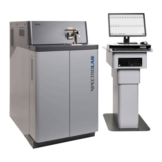
- Page 1 Das verknüpfte Bild kann nicht angezeigt werden. Möglicherweise wurde die Datei verschoben, umbenannt oder gelöscht. Stellen Sie sicher, dass die Verknüpfung auf die korrekt SPECTROLAB Stationary metal analyzer Original operating instructions...
-
Page 3: Table Of Contents
Table of Contents Description of instrument ..................5 Description .......................... 5 Function ..........................5 Overview ..........................6 1.3.1 Unit (left side) ......................6 1.3.2 Instrument (right-hand side) .................. 7 1.3.3 Instrument (inside) ....................8 1.3.4 Instrument (back) ....................9 1.3.5 Spark stand ...................... - Page 4 Measuring procedure ......................28 6.4.1 Preparing the measuring procedure ..............29 • iCALising the measuring device (iCAL) ............... 29 • Standardizing the measuring device (optional) ........... 30 • Changing the base (multi-base instruments only) ..........30 6.4.2 Start the measurement ..................31 Maintenance .....................
-
Page 5: Description Of Instrument
Description of instrument Description of instrument Description Instrument: SPECTROLAB Model: LAS01 Type/Part No.: 76004143 Function Sample material is evaporated by spark discharge inside the unit. In this process, the released atoms and ions are excited and emit light. This light is directed into the optical systems and measured using sensors. -
Page 6: Overview
Description of instrument Overview 1.3.1 Unit (left side) Fig. 1 Component Component Filter mat spark excitation (plasma Sample clamp generator) Unlocking mechanism for Start/Stop measurement protective cover Filter mat for cooling system On/Off switch spark excitation (plasma generator) Filter mat electronic room —... -
Page 7: Instrument (Right-Hand Side)
Description of instrument 1.3.2 Instrument (right-hand side) Fig. 2 Component Component Sample clamp Door opener Start/Stop measurement Access to the setting gage electrode, Allen key, wash bottle On/Off switch and filter bottle (inside the Spark excitation instrument) (plasma generator) Unlocking mechanism for protective cover SPECTROLAB —... -
Page 8: Instrument (Inside)
Description of instrument 1.3.3 Instrument (inside) Fig. 3 Component Component Gas-washing bottle ICAL sample(s) Gas cleaning cartridge Setting gage electrode Notice! Only qualified personnel shall be permitted to change the cartridge. Exhaust hose Filter bottle Allen key for electrode holder —... -
Page 9: Instrument (Back)
Description of instrument 1.3.4 Instrument (back) Fig. 4 Component Component Argon connection Mains connection socket PC data transmission connection SPECTROLAB — 23.07.2020 — 9... -
Page 10: Spark Stand
Description of instrument 1.3.5 Spark stand Fig. 5 Component Component Access to electrode clamp Locking wheel for contact Sparky stand plate Electrode and spark stand insert Clamp (swinging) Outlet to filter system Contact (movable) Electrode holder Start/Stop measurement Holder for fiber-optics to air optics On/Off switch for spark excitation (plasma generator) —... -
Page 11: Safety
Safety Safety Every user of the instrument must have read and understood these operating instructions. This applies in particular to the safety instructions. Symbols used The following symbols are used in these abbreviated operating instructions and/or on the instrument. If required, additional important information is available in connection with these symbols. -
Page 12: User Information
Safety Notice! This sign warns of activities or conditions that may adversely affect the function of the instrument. Information Displays information that is important for the correct and safe use of the instrument. User information Non-compliance with the operating and safety instructions may lead to injuries ... -
Page 13: Intended Use
Safety Compliance with the relevant safety regulations for the use of auxiliary aids and operating equipment is mandatory. Carry out only those maintenance tasks that is described in the chapter "Maintenance" of the operating instructions. The operating personnel are not permitted to perform any other maintenance work. -
Page 14: Samples
Safety 2.3.1 Samples Only dry metal samples must be measured. Warning! Risk of injury and health hazard! Risk of injury and health hazard due to pressurized or combustible samples. Pressurized or flammable samples must not be measured. 2.3.2 Preparing the Sample Warning! Harmful and toxic substances! During the preparation of samples, e.g. -
Page 15: Sample Material
Safety 2.3.3 Sample material Warning! Toxic substances! The sparking process produces a black precipitate (metal condensate). The condensate could be toxic or flammable, depending on the sample material. Metal vapors may be generated by sparks of the sample material. Depending on the sample material, these vapors may be toxic, e.g. -
Page 16: Gas Cleaning Cartridge
Safety 2.3.5 Gas cleaning cartridge The instrument contains a gas cleaning cartridge. Only a qualified technician shall be permitted to change the gas cleaning cartridge. Warning! Toxic substances! The content of the gas cleaning cartridge is toxic. Compliance with the safety data sheet is mandatory. To request the data ... -
Page 17: Gas Supply
Safety 2.3.8 Gas supply Information! Measurement errors! Impurities in the argon supply cause measuring errors. Ensure the installation of the argon supply line is free of oil and grease. Only argon must be used when operating the instrument. Argon quality (min.) 4.8 (99.998% Ar) with O <3ppm, N <10ppm,... -
Page 18: Residual Risks
Safety Residual risks This instrument has been manufactured in accordance with the latest state-of-the- art technology. Residual risks cannot be completely excluded, however. Notice! The light inlet window of the air optics is located below the spark stand. Protective gloves must be worn to prevent cuts and contact with metal ... - Page 19 Safety Warning! Risk of suffocation! The instrument is operated with argon. Argon is heavier than air. It can accumulate in a closed room, especially on the floor or lower-lying areas. Ensure that adequate ventilation is provided. If necessary, install oxygen ...
-
Page 20: Technical Data
Technical data Technical data Description Value Instrument height 1405 mm; 55.3" Instrument width 770 mm; 30.3" Instrument depth 1360 mm; 53.5" Instrument weight approx. 375 kg; ~ 826 lbs Power supply 198 - 253 VAC, 50/60 Hz Power during measurement 1.0 kVA Power during stand-by 0.4 kVA... -
Page 21: Transportation/Setting-Up
Transportation/Setting-up Transportation/Setting-up Notice! Damage to instrument! Improper transport may cause damage to the instrument or to other property within the surroundings. Only specifically trained personnel shall be permitted to transport the instrument in its transport packaging. If the usage site must be changed, please contact our service ... -
Page 22: Space Requirements
Transportation/Setting-up Space requirements Storage Storage conditions: The instrument must be stored in a dry place Room temperature -15°C – +45°C (5°F – 113°F) — 22 SPECTROLAB — 23.07.2020... -
Page 23: Gas Supply
Transportation/Setting-up Gas supply Information: Measurement errors! Impurities in the argon supply cause measuring errors. Ensure the installation of the argon supply line is free of oil and grease. The spectrometer requires an argon supply line. A suitable pressure reducer is required for the argon supply (bottles or liquid gas tank). -
Page 24: Initial Start-Up
Initial start-up Initial start-up Preparing the instrument for use Before switching on the instrument, proceed as follows: Check whether the power supply of the instrument supplies the correct input voltage.(198 - 253 VAC, 50/60 Hz). Check if the mains voltage selector switch of the PC is set to the proper input voltage (230V/115V). -
Page 25: Operation
Operation Operation Overview of controls Fig. 6 Control element Function Switch Start/Stop measurement Switch Switches the plasma generator on/off, see chapter 6.2. SPECTROLAB — 23.07.2020 — 25... -
Page 26: Switching On The Instrument
Operation Switching on the instrument Information To operate the instrument in compliance with the specification, it should be stabilized after switching it on. After reaching the optical system's target temperature (20°C, 68°F), the system may require at least two hours to stabilize. When starting the instrument for the first time, it is recommended to rinse the instrument with argon for a longer period of time in order to remove any oxygen and moisture that have penetrated the system. -
Page 27: Switching Off The Instrument
Operation Switching off the instrument Information If the instrument was completely switched off, restarting may take some time as the optics need to reach the right temperature and the system must be flushed with argon. It is recommended to leave the instrument connected to the power supply and to leave the argon supply line open all the time. -
Page 28: Measuring Procedure
Operation Measuring procedure Warning of hand injury! Springs are used to keep the sample clamp in position. However, the clamp may fold down unexpectedly. If your hand is caught underneath the clamp, this may cause injuries. Never place your hand under the sample clamp. ... -
Page 29: Preparing The Measuring Procedure
Operation 6.4.1 Preparing the measuring procedure Information An optimum measurement requires a good argon atmosphere inside the spark stand. Therefore, the opening of the spark stand must always be covered. This will make it more difficult for ambient air to enter the spark stand. A flat sample is highly recommended. -
Page 30: Standardizing The Measuring Device (Optional)
Operation Standardizing the measuring device (optional) Information Prior to any standardization, the instrument must be iCALized. In addition, a verification with certified standards must be performed after any standardization. In order to standardize the instrument, proceed as follows: Start the standardization function using the F7 function key. Follow the instructions on the screen and perform the necessary measurements with the profiling samples. -
Page 31: Start The Measurement
Operation 6.4.2 Start the measurement Information Use the electrode brush in order clean the electrode tip after each measurement. After 200 measurements, a brush must be used to clean around the electrode and to clean the bottom of the insert. A brush of the same type as that used for electrode cleaning can be used. -
Page 32: Maintenance
Maintenance Maintenance Information In order to ensure the availability and operational safety of the equipment, we recommend having the system checked for correct operation and performance at least once per year by specialized technicians. To find contact addresses of service organizations authorized by SPECTRO go to www.spectro.com Maintenance Reminder The instrument is equipped with a diagnostic system that will prompt you to proceed with a variety of maintenance tasks. -
Page 33: Maintenance Schedule
Maintenance Maintenance schedule Start of work Tasks to be performed 1. Check the argon supply. The min. pressure in the bottle is 10 bar. 2. Diagnosis system - maintenance or Will be specified by the diagnosis system. check the number of measurements. 3. -
Page 34: Cleaning The Uv Optics Light Inlet Window
Maintenance Cleaning the UV optics light inlet window Warning of hazardous voltage! While the instrument is switched on, the spark stand presents a risk of electrical shock. Shut down the Plasma generator (excitation unit) during all work on the spark ... - Page 35 Maintenance Loosen the union nut (1). Fig. 9 Remove the fiber optic holder (2) from the spark stand. Loosen the window holder (3) from the spark stand. The quartz window is located between the holder and the O-ring. Direct contact with the optical surfaces must be avoided! Fig.
- Page 36 Maintenance Clean the light channel (5) with a grease-free cloth or a bottle brush with plastic bristles. Fig. 12 If necessary, use a grease-free cloth to clean the O-ring (6). Fig. 13 10. Reassemble components in reverse order. Cleaning of the air optics light inlet window is now complete. ...
-
Page 37: Cleaning The Spark Stand
Maintenance Cleaning the spark stand Warning! High voltage! If the instrument is switched on, there a risk of electrical shock. Shut down the Plasma generator (excitation unit) during all work on the spark stand. Warning! Toxic substances! The sparking process produces a black precipitate (metal condensate). The condensate could be toxic or flammable, depending on the sample material. - Page 38 Maintenance The sparking process soils the spark stand with a black precipitate (metal condensate). This metal condensate may create a conductive connection between the electrode and the metal structure of the spark stand wall. To clean the spark stand, proceed as follows: Turn off the Plasma generator (1).
- Page 39 Maintenance For removal of the electrode (1), unscrew the sealing plug (2). Behind the plug there is a through hole in order to reach the fixing screw of the electrode. Fig. 16 Loosen the fixing screw of the electrode using the Allen key (AF 2.5) until the electrode can be removed.
- Page 40 Maintenance Use a dry, grease-free cloth to clean both sides of the spark stand plate (1). 10. Use a dry, grease-free cloth to clean the surface of the spark stand body. 11. Use a dry, grease-free cloth or a bottle brush with plastic bristles to clean the light channel (2).
- Page 41 Maintenance 14. Insert the electrode (1) into the spark stand opening. Fig. 22 15. Use the setting gage (1) in order to align the electrode. Press the setting gage with the 3.4 mm shoulder into the spark stand opening and at the same time use the Allen key (2) (AF 2.5) to screw the electrode screw...
-
Page 42: Cleaning The Exhaust Filter System And Changing The Filter Insert
Maintenance Cleaning the exhaust filter system and changing the filter insert Warning! Toxic or flammable substances! The sparking process produces a black precipitate (metal condensate). The condensate could be toxic or flammable, depending on the sample material. Protective gloves and safety goggles must always be worn when cleaning the ... - Page 43 Maintenance Use the hook spanner (1) to remove the filter container (2). Fig. 27 Replace the filter and screw the filter container back into the holder. Ensure that the O-ring (1) is clean and sits inside the groove. If necessary, use a clean cloth to clean the O- ring.
- Page 44 Maintenance Pull the nozzle (2) out of the water hose. Use a cloth to clean the nozzle and replace it. Screw the water bottle back into the holder. The water bottle should only be tightened by hand. Fig.
-
Page 45: Inspecting The Gas-Washing Bottle
Maintenance Inspecting the gas-washing bottle Warning! Toxic or flammable substances! The sparking process produces a black precipitate (metal condensate). The condensate could be toxic or flammable, depending on the sample material. Protective gloves and safety goggles must always be worn when cleaning the ... - Page 46 Maintenance Make sure that the O-ring (1) sits in the groove and is clean. If necessary, use a clean cloth to clean the O-ring. Screw the gas-washing bottle back manually. Fig. 34 Checking/changing the water is now complete. — 46 SPECTROLAB —...
-
Page 47: Replacing The Filter Mats
Maintenance Replacing the filter mats The SPECTROLAB LAS01 has three openings on the left side for the fresh air supply (cooling system (1), electronics room (2) and plasma generator/spark stand (3)). The filter mats for these openings are all of the same size, whereby two filter mats are required for opening 1. -
Page 48: Replacing The Icalization Sample
Maintenance Remove the old filter mats. Install the new filter mats. Reinstall the covers. Insert the covers from above and press against the top left and right corners of the cover until it clicks into place. Now, the filter mats are replaced. ... -
Page 49: Status Messages
Status messages Status messages The status information is displayed in the footer of the software. These indications provide important information about the status of the instrument. The following information is available: Status information Description Ready The instrument is ready for measurement if all specifications according to chapter 6.4.1 on page 29 have been met. -
Page 50: Troubleshooting
Troubleshooting Troubleshooting Malfunction Cause Remedy The instrument cannot be The power plug is not Check if the power plug was switched on. plugged in properly. properly plugged in. Power is not available. Check the power supply. Defective fuse. Check the fuse inside the mains connection socket. - Page 51 Troubleshooting Malfunction Cause Remedy Limit values are not Insufficient intensity. 1. Check argon. maintained during iCALising. 2. Clean spark stand, adjust electrode. 3. Clean light inlet window. 4. Re-profile instrument again and, if necessary, contact the Service Department. During standardization, Insufficient intensity.
-
Page 52: Error Messages
Troubleshooting Error messages Error Cause Remedy When starting the “Spark Communication Exit the “Spark Analyzer Pro Analyzer Pro” software, the LAB” software. instrument switches into Disconnected the DEMO mode. spectrometer from the power for a short time. After a waiting period of approx. 60 sec., restart the “Spark Analyzer Pro LAB”... -
Page 53: Diagnosis Tool
Troubleshooting Diagnosis tool An LED symbol in the status bar permanently indicates the general status of the instrument. To open the diagnostic system, click the green or red LED symbol in the lower right-hand corner of the status bar. Fig. 38 When the instrument is ready for operation, the green LED symbol is lit. -
Page 54: Spare Parts And Consumables
Spare parts and consumables Spare parts and consumables You can find the spare parts and consumables for this instrument under "Support - Parts Catalogue" (Service – Parts Catalogue) on our website at www.spectro.com. De-commissioning Only organizations or persons authorized by the instrument manufacturer shall be permitted to de-commission the instrument. -
Page 55: Ec Declaration Of Conformity
EC Declaration of Conformity EC Declaration of Conformity SPECTROLAB — 23.07.2020 — 55...
Need help?
Do you have a question about the Spectrolab LAS01 and is the answer not in the manual?
Questions and answers