Table of Contents
Advertisement
Quick Links
Advertisement
Table of Contents

Related Manuals for Advanced Micro Controls Inc. 1700 Series

Summary of Contents for Advanced Micro Controls Inc. 1700 Series
- Page 1 Artisan Technology Group is your source for quality new and certified-used/pre-owned equipment SERVICE CENTER REPAIRS WE BUY USED EQUIPMENT • FAST SHIPPING AND DELIVERY Experienced engineers and technicians on staff Sell your excess, underutilized, and idle used equipment at our full-service, in-house repair center We also offer credit for buy-backs and trade-ins •...
- Page 2 Series 1700 Intelligent Resolver Interface Modules Allen-Bradley 1731 1741 1771 I/O 1732 1742 1733 1743 Module 1734 1744 Manual: 940-57011 Artisan Technology Group - Quality Instrumentation ... Guaranteed | (888) 88-SOURCE | www.artisantg.com...
-
Page 3: General Information
General Information Important User Information The products and application data described in this manual are useful in a wide variety of different applications. Therefore, the user and others responsible for applying these products described herein are responsible for determining the acceptability for each application. While efforts have been made to provide accurate information within this manual, AMCI assumes no responsibility for the application or the completeness of the information contained herein. -
Page 4: About This Manual
About This Manual Introduction This manual explains the operation, installation, programming, and servicing of eight Series 1700 Intelligent Resolver Interface Modules for the Allen-Bradley 1771 I/O programmable controller systems. These modules are the 1731, 1732, 1733, 1734, 1741, 1742, 1743, and 1744. - Page 5 About This Manual Notes ADVANCED MICRO CONTROLS INC. Artisan Technology Group - Quality Instrumentation ... Guaranteed | (888) 88-SOURCE | www.artisantg.com...
- Page 6 Chapter 1 Series 1700 Introduction This chapter serves as an introduction to the Series 1700 modules. It highlights the Series 1700 family members, potential applications, compatible transducers, and all of the modules’ features, including those added since the last revision. Overview The Series 1700 modules are Allen Bradley 1771 I/O compliant cards that convert resolver signals to...
- Page 7 Read Status Mode. Series 1700 Family Members The twelve modules in the 1700 series are shown in the table below. The shaded out models are multi-turn modules not covered in this manual. Refer to About this Manual, pg. I Introduction, for more information on the manuals for these modules.
- Page 8 Chapter 1 Series 1700 Introduction Brushless Resolver Description The brushless resolver is unsurpassed by any other type of rotary position transducer in its ability to withstand the harsh industrial environment. An analog sensor that is absolute over a single turn, the resolver was originally developed for military applications and has benefited from more than 50 years of continuous use and development.
- Page 9 Chapter 1 Series 1700 Introduction AMCI Compatible Transducers Table 1.2 lists the AMCI transducers compatible with the 1700 modules. Model Shaft Mount Turns Comments R11X-J10/7 0.120” Servo NEMA 1, size 11 resolver R11X-J12/7 0.188” Servo NEMA 1, size 11 resolver HT-6 0.188”...
- Page 10 Chapter 1 Series 1700 Introduction Other Compatible Transducers In addition to AMCI transducers, the 1700 modules directly support Autotech transducers. The Autotech models supported are: hý All SAC-RL100 Transducers. (Size 40, NEMA 13) All E6R and E7R-RL101 Transducers. (Size 25, NEMA 13) hý...
-
Page 11: Programmable Parameters
Chapter 1 Series 1700 Introduction The remainder of this chapter introduces the many programmable features of the 1700 modules. It also introduces backplane programming concepts that allows you to control the module from the processor instead of using the modules keyboard and display. - Page 12 Chapter 1 Series 1700 Introduction Transducer Setup Parameters Tachometer Response This parameter sets the time between tachometer updates and the tachometers resolution. Update times are 32, 60, 120, or 240 mSec. The two resolutions, available only with the 240 mSec update time, are 1.0 or 0.1 RPM. hý...
-
Page 13: Preset Value
Chapter 1 Series 1700 Introduction Transducer Setup Parameters (continued) Circular Offset The Circular Offset lets you change the position count without rotating the transducer shaft. This offset is most commonly used to force the position to the correct count after the machine has been mechanically aligned. -
Page 14: Transfer Type
Chapter 1 Series 1700 Introduction Module Setup Parameters Data Format This parameter allows you to choose the format of the position and tachometer data reported over the backplane. The choices are Binary or BCD. It is included for PLC-2 users that require BCD data for PLC-2 math instructions. - Page 15 Chapter 1 Series 1700 Introduction Module Setup Parameters (continued) Single Transfer Length The Single Transfer Length parameter is a new parameter used to specify either a 16 or 32 bit transfer. This parameter is only available if you have selected single transfers with the Transfer Type parameter.
-
Page 16: Auxiliary Commands
Chapter 1 Series 1700 Introduction Backplane Programming When a Series 1700 module is configured to use block transfers, you have the option of programming the module using data sent to it by block transfer writes. (See Transfer Type Parameter and PLC Program Parameter sections, pgs. 1-8, 1-9.) The programming format is a series of Program Instructions as shown below. - Page 17 Chapter 1 Series 1700 Introduction Auxiliary Commands (continued) Enter Read Status Mode - This command puts the module in read status mode. hý While in this mode, the module will transmit parameter values instead of position and tachometer data. Four additional commands are enabled while in this mode that allow you to specify which parameter values are to be read back.
-
Page 18: Front Panel Description
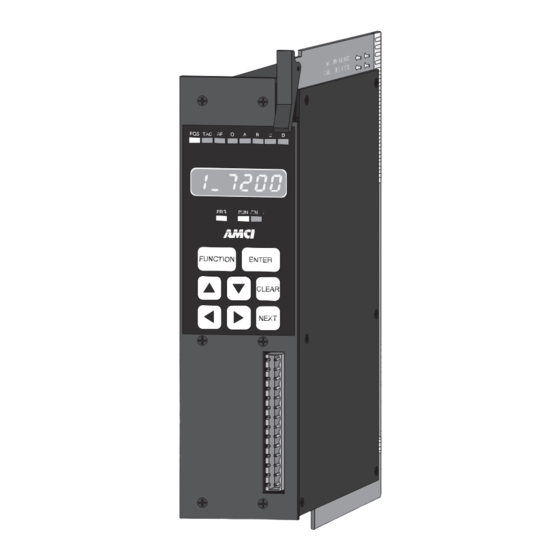
Chapter 2 Module Description This chapter describes the physical layout of a Series 1700 module as well as keyboard programming. Front Panel Description Program Switch - (On other side of PC Board, hidden from view.) Used to enable programming the module from the keyboard. -
Page 19: Program Switch
Chapter 2 Module Description Program Mode vs. Display Mode The front panel has two operating modes. Program Mode – (Yellow PRG light on) The parameters can be modified from hý the keyboard. The position can be preset by pressing the >CLEAR@ key while displaying the position value. - Page 20 Chapter 2 Module Description Using the Function Display and Keyboard You can examine position and tachometer values as well as inspect or program all of the programmable parameters using the display and keyboard. The >FUNCTION@ key, along with the >Ç@ and >Æ@ keys, are used to cycle between the displays. Figure 2.3 shows the display order. POWER UP Navigating in Display Mode When compared to program mode, display...
-
Page 21: Switching Between Channels
Chapter 2 Module Description Using the Function Display and Keyboard (continued) Switching Between Channels Pressing the >NEXT@ key will cycle through the transducer channels when displaying the position value, tachometer value, or transducer setup parameters. You will remain in the same display, only switching channels. - Page 22 Chapter 2 Module Description Position Display As shown in figure 2.5a, the position display shows the current position when a transducer is properly attached to the channel. The first digit is the transducer channel. If you have a multi-channel module, press the >NEXT@ key to cycle through the additional position displays. If there is a transducer fault on the input channel, the position display will change to the one shown in figure 2.5b.
- Page 23 Chapter 2 Module Description Transducer Setup Parameters The following are the front panel displays of the transducer setup parameters along with default values, range of values, and any special programming instructions. The first digit of these displays usually tells you which channel is being displayed. The one exception is the count direction display.
- Page 24 Chapter 2 Module Description Transducer Setup Parameters (continued) Circular Offset Pg. 1-7 Default: 0 PLC SERIES Range: 0 to (Scale Factor - 1) Programming the Scale Factor parameter resets the Circular Offset to zero. Figure 2.10 Circular Offset Linear Offset Pg.
- Page 25 Chapter 2 Module Description Module Setup Parameters (continued) Transfer Type Pg. 1-8 Default: Block transfer Range: Block PLC SERIES Single Figure 2.14 Transfer Type PLC Program Pg. 1-8 Default: Read Only Range: Read Only PLC SERIES Program Enabled This parameter is only shown when the Transfer Type parameter is set to block transfer.
-
Page 26: Error Messages
Chapter 2 Module Description Error Messages There are three types of faults that a 1700 module will recognize. Transducer Fault (Error 1) – A problem exists on a transducer channel. hý nvRAM Fault (Error 2) – A problem exists with the non-volatile RAM or hý... - Page 27 Chapter 2 Module Description Error Messages (continued) Reference Voltage Fault A 1700 module stores adjustment constants in the nvRAM memory that allow it to set the reference voltage for either AMCI or Autotech trans- PLC SERIES ducers. Usually, these constants can be restored automatically when a nvRAM fault is cleared.
-
Page 28: Power Requirements
Chapter 3 Installation This chapter describes how to install the Series 1700 module into the I/O chassis. It also give information on installing AMCI transducers. This includes information on transducer mounting, shaft loading, and cable installation. Information on interfacing Autotech transducers is also included. Power Requirements The 1700 modules draw power from the I/O chassis +5Vdc supply. -
Page 29: Chapter 3 Installation
Chapter 3 Installation Transducer Specifications Specification All HT and HTT’s All H25’s HT-6 Shaft Diameter 0.625" 0.375" 0.188" Radial Shaft Loading 40 lbs. Max. 400 lbs. Max. 8 lbs. Max. Axial Shaft Loading 200 lbs. Max. 20 lbs. Max. 4 lbs. Max. Starting Torque 8 oz.in. - Page 30 Chapter 3 Installation Transducer Outline Drawings (continued) HT-20: Anodized Aluminum Body, 1070 Steel Shaft, NEMA 13 2.500" (63.50) 4.75" (120.7) 2.000" (50.80) 0.750" KEYWAY (19.05) 3.250" 0.500" (82.55) (12.70) 0.1885(4.79) 0.106(2.69) 1.000" DEEP X 1.0(25.4) 0.1895(4.81) 0.108(2.74) (25.40) 0.187(4.75) SQ. X 1.0(25.4) 0.188(4.78) 1.000"...
- Page 31 Chapter 3 Installation Transducer Outline Drawings (continued) H25FE: Anodized Aluminum Body, 303 Stainless Steel Shaft, NEMA 4 0.700" max. (17.78) ( ) = Dimensions in millimeters Total clearance of 3.5" (89) needed for removal of 1.032" 0.218" dia. (5.54) mating connector. (26.21) 0.250"...
- Page 32 Chapter 3 Installation Transducer Outline Drawings (continued) H25FS: Anodized Aluminum Body, 303 Stainless Steel Shaft, NEMA 4 ( ) = Dimensions in millimeters 1.43" sq. (36.3) 1.13" max. (28.7) Total clearance of 3.5" (89) needed for removal of mating connector. 2.65"...
- Page 33 Chapter 3 Installation Transducer Outline Drawings (continued) H25FL: Anodized Aluminum Body, 303 Stainless Steel Shaft, NEMA 4 1.032" 0.218" dia. (5.54) (26.21) 0.250" (6.35) Four places 0.300" typ. (7.62) LIQUID TIGHT STRAIN RELIEF Hummel P/N 1.293.1201.71 (9.517) 0.3747" Accepts Cables 0.20" (5.1) to 0.35"...
- Page 34 Chapter 3 Installation Transducer Outline Drawings (continued) HT-400: Anodized Aluminum Body, 1070 Carbon Steel Shaft, NEMA 4 4.00" Dia. ± 0.01" 1" NPT Thread (101.6) (0.3) #10-32 UNF-2B. 0.50" min. depth. (12.7) 6.41" (162) Four places, 90° apart on 2.50" B.C.
- Page 35 Chapter 3 Installation Transducer Cable Installation Use the table below to determine the correct cable and connectors for your application. Cables that have been assembled and tested are available from AMCI under the given part numbers. If you are making your own cables, cable and connectors can be ordered from AMCI. Belden Cable # Module AMCI Part #...
- Page 36 Chapter 3 Installation Transducer Cable Wiring Diagrams C1T-(x) Wiring Diagram: For 1731 & 1741, (x) = length in feet S1, S2 SHIELDS Shields Transducer Connector Module Connector AMCI Part #: MS-16 BELDEN 9873 Cable AMCI Part #: MS-8 Bendix #: For cable lengths greater than Phoenix #: MSTB2.5/8-ST-5.08...
- Page 37 Chapter 3 Installation Transducer Cable Wiring Diagrams (continued) C3T-(x) wiring Diagram: For 1733 & 1743, (x) = length in feet Figure 3.17 C3T-(x) Wiring Diagram 3-10 ADVANCED MICRO CONTROLS INC Artisan Technology Group - Quality Instrumentation ... Guaranteed | (888) 88-SOURCE | www.artisantg.com...
- Page 38 Chapter 3 Installation Transducer Cable Wiring Diagrams (continued) C4T-(x) Wiring Diagram: For 1734 & 1744, (x) = length in feet Figure 3.18 C4T-(x) Wiring Diagram 20 Gear Drive, Plymouth Ind. Park, Terryville, CT 06786 3-11 Tel: (860) 585-1254 Fax: (860) 584-1973 Artisan Technology Group - Quality Instrumentation ...
- Page 39 Chapter 3 Installation IMT Transducer Interface Module The IMT is an interface module that simplifies field wiring to a 1733, 1734, 1743 or 1744. This module has terminal blocks that connect four C1T transducer cables to a single eight foot cable.
-
Page 40: Transducer Wiring
Chapter 3 Installation Autotech Transducer Installation Transducer Mounting Series 1700 modules support Autotech SAC-RL100, E6R and E7R-RL101, and SAC- RL101-010 transducers. Refer to Autotech Controls literature for dimensional drawings and mounting recommendations. Even though Autotech transducers are usable, we strongly recommend using AMCI trans- ducers whenever possible. - Page 41 Chapter 3 Installation Notes 3-14 ADVANCED MICRO CONTROLS INC Artisan Technology Group - Quality Instrumentation ... Guaranteed | (888) 88-SOURCE | www.artisantg.com...
-
Page 42: Definition Of Terms
Chapter 4 AMCI Module Addressing This chapter explains how to address a 1700 module in a PLC-5 programmable controller system. If you are using a PLC-2 or PLC-3 system, contact AMCI if you need assistance. When you configure your programmable controller system, a unique address is assigned to each slot of each chassis in the system. - Page 43 Chapter 4 AMCI Module Addressing Definition of Terms (cont'd) 2-Slot Addressing Two slot addressing assigns one I/O group to each slot pair in the chassis. Block transfers use the I/O group for control bits. You cannot use 32 bit single transfers if the chassis is configured with 2-slot addressing.
-
Page 44: Addressing Examples
Chapter 4 AMCI Module Addressing Addressing the 1700 as a Single Transfer Module Once a 1731 or 1741 is configured correctly, the processor reads position and tachometer data with single transfers. To use this data, you must know the memory locations in the input image table associated with the module. -
Page 45: Restrictions And Warnings
Chapter 4 AMCI Module Addressing Addressing Examples (cont'd) I/O Group I/O Rack Number 0 I/O Rack Number 1 1-Slot Addressing Number Rack Number: 01 I/O Group Numbers: 0,1 Module Slot Number: 0 BT Address: 0110 16 bit single Position Addr: I:011 32 bit single Position Addr: I:010 32 bit single Tach Addr: I:011 Module Slot Numbers... - Page 46 Chapter 5 PLC-5 BT Instructions Overview All PLC-5 processors have Block Transfer Instructions in their instruction sets. There are five parts to PLC-5 BT Instructions. They are: hý Module Address – The I/O rack, I/O group, and module slot numbers where the module is located.
- Page 47 Chapter 5 PLC-5 BT Instructions File Length (continued) Block Transfer Writes When programming a BTW instruction, you must specify the exact number of words that contain your programming instructions. You cannot use a file length of zero with a BTW instruction unless you are actually transmitting sixty-four words.
- Page 48 Chapter 5 PLC-5 BT Instructions Programming Example The following example assumes 1-Slot addressing with a 1741 module in I/O Rack 2, I/O Groups 4 & 5 of the system. BLOCK XFER READ Rung 1: BTR Instruction to the AMCI RACK module.
- Page 49 Chapter 5 PLC-5 BT Instructions PLC-5 Restrictions and Warnings hý It is important to have the 1700 module installed in a single slot pair. See chapter 3, pg. 3-1, Installing the Module. hý When using the 1700 module in a remote chassis, the Remote I/O Adapter must be a 1771 - ASB, Series B, Firmware Rev.
-
Page 50: Programming Structure
Chapter 6 Backplane Programming This chapter contains all of the information needed to learn how to use block transfer writes to program a 1700 module from the backplane. This information includes data on programming structure, programming instructions, and error codes. Information on the format of the data sent to the processor while it is in Read Status Mode is also included. -
Page 51: Program Instructions
Chapter 6 Backplane Programming Program Instructions Program Instructions are broken down into three categories Auxiliary Commands – Nine instructions that affect the operation of the module hý and do not have data words associated with them. These instructions are: Disable Keyboard Programming Enable Keyboard Programming Clear Errors Preset Transducer 1-4 (Four separate instructions) - Page 52 Chapter 6 Backplane Programming Transducer Setup Instructions Command Command Comments Word (X = {0,1}, Y = {1...F}). Use this instruction to program the Transducer 1 88XYh transducer setup parameters of transducer 1. Setup Digit X Digit Y 0 0 0 Scale Factor Circular Offset Linear Offset...
- Page 53 Chapter 6 Backplane Programming Transducer Setup Instructions (continued) Command Command Comments Word (X = {0,1}, Y= {1…F}). Use this instruction to program the transducer Transducer 2 98XYh setup parameters of transducer 2. The format of the instruction is Setup identical to the Transducer 1 Setup instruction. (X = {0,1}, Y= {1…F}).
- Page 54 Chapter 6 Backplane Programming Read Status Data Format The four figures below show the format of read status data. Because a 1700’s block transfer read length is fixed, the format of the data is based on the module you are using. A 1731 or 1741 can transmit only one parameter value at a time.
-
Page 55: Status Word
Chapter 6 Backplane Programming Status Word The status word is broken down into two bytes. The low byte, bits 0 – 7, is used to report hardware faults. The format of this byte is shown in figure 6.3. The high byte, bits 8 –15, is used to report programming errors. - Page 56 Chapter 7 Data Fo rma t This chapter outlines the format of the position and tachometer data sent from a 1700 module with either block or single transfers. Block Transfer Data Format When a block transfer read instruction accesses a 1700 module, the module transmits two 16 bit words for each transducer channel.
-
Page 57: Data Format
Chapt er 7 Data Format Block Transfer Data Format (continued) Status Word The status word is transmitted when the 1700 is configured to be programmable from the backplane. It is broken into two bytes. The low byte, bits 0 – 7, is used to report hardware faults. The format of this byte is shown in figure 7.2. - Page 58 Chapter 7 Data Fo rma t Single Transfer Data Format A 1731 or 1741 module can be configured to transmit its position and tachometer information with single transfers by setting its Transfer Type parameter to single transfer and its Single Transfer Length parameter to either 16 or 32 bits. When configured for 16 bit transfers, only the position data is available.
- Page 59 Chapt er 7 Data Format Notes ADVANCED MICRO CONTROLS INC Artisan Technology Group - Quality Instrumentation ... Guaranteed | (888) 88-SOURCE | www.artisantg.com...
- Page 60 Chapter 8 Sample PLC-5 Program The following ladder logic program is an example of how block transfer instructions can be used to read and program a 1700 module using block transfers. The program shows how to read and buffer data from a 1700 module, and how a single block transfer write instruction can be used to send various program instructions to the module.
- Page 61 Chapter 8 Sample PLC-5 Program ADVANCED MICRO CONTROLS INC Artisan Technology Group - Quality Instrumentation ... Guaranteed | (888) 88-SOURCE | www.artisantg.com...
- Page 62 Chapter 8 Sample PLC-5 Program 20 Gear Drive, Plymouth Ind. Park, Terryville, CT 06786 Tel: (860) 585-1254 Fax: (860) 584-1973 Artisan Technology Group - Quality Instrumentation ... Guaranteed | (888) 88-SOURCE | www.artisantg.com...
- Page 63 Chapter 8 Sample PLC-5 Program ADVANCED MICRO CONTROLS INC Artisan Technology Group - Quality Instrumentation ... Guaranteed | (888) 88-SOURCE | www.artisantg.com...
- Page 64 Chapter 8 Sample PLC-5 Program 20 Gear Drive, Plymouth Ind. Park, Terryville, CT 06786 Tel: (860) 585-1254 Fax: (860) 584-1973 Artisan Technology Group - Quality Instrumentation ... Guaranteed | (888) 88-SOURCE | www.artisantg.com...
- Page 65 Chapter 8 Sample PLC-5 Program ADVANCED MICRO CONTROLS INC Artisan Technology Group - Quality Instrumentation ... Guaranteed | (888) 88-SOURCE | www.artisantg.com...
- Page 66 This is text added to the page so that the page will print. The color is white so that the page appears blank. Artisan Technology Group - Quality Instrumentation ... Guaranteed | (888) 88-SOURCE | www.artisantg.com...
- Page 67 ADV ANC ED MIC RO CONTROLS INC. 20 GEAR DRIVE, TERRYVILLE, CT 06786 T: (860) 585-1254 F: (860) 584-1973 amcicontrols.com LEADERS IN ADVANCED CONTROL PRODUCTS Artisan Technology Group - Quality Instrumentation ... Guaranteed | (888) 88-SOURCE | www.artisantg.com...
- Page 68 Artisan Technology Group is your source for quality new and certified-used/pre-owned equipment SERVICE CENTER REPAIRS WE BUY USED EQUIPMENT • FAST SHIPPING AND DELIVERY Experienced engineers and technicians on staff Sell your excess, underutilized, and idle used equipment at our full-service, in-house repair center We also offer credit for buy-backs and trade-ins •...
Need help?
Do you have a question about the 1700 Series and is the answer not in the manual?
Questions and answers