
Related Manuals for Intellinet 560917


Summary of Contents for Intellinet 560917
- Page 1 24-‐PORT W EB-‐MANAGED G IGABIT E THERNET SWITCH W ITH 2 S FP P ORTS USER M ANUAL MODEL 5 60917 INT-‐560917-‐UM-‐0315-‐01...
-
Page 2: Table Of Contents
Web-Managed Gigabit Ethernet Switch Table o f C ontents Chapter 1 P roduct I ntroduction ...................... 4 1.1 P roduct O verview ........................ 4 1.2 ... - Page 3 Web-Managed Gigabit Ethernet Switch 4.4.4 P ort V LAN M embership .................... 3 1 4.4.5 P rotocol V LAN G roup S etting .................. 3 1 4.4.6 ...
- Page 4 Web-Managed Gigabit Ethernet Switch 4.11.1 L LDP G lobal S etting .................... 7 2 4.11.2 L LDP P ort S etting ...................... 7 3 4.11.3 L LDP L ocal D evice ....................... 7 3 4.11.4 ...
-
Page 5: Chapter 1 Product Introduction
Web-Managed Gigabit Ethernet Switch Chapter 1 Product Introduction Congratulations on your purchase of the Web-Managed Gigabit Ethernet Switch. Before you install and use this product, read this manual carefully for a full understanding of its functions . 1.1 Product Overview The Web-Managed Gigabit Ethernet Switch provides a seamless network connection. -
Page 6: External Component Description
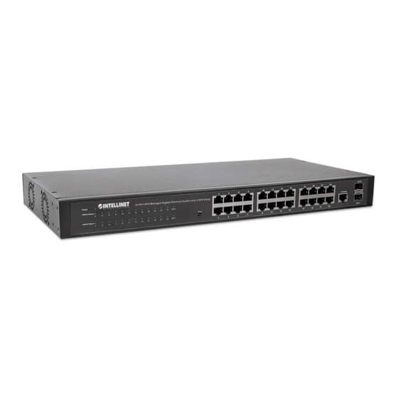
Web-Managed Gigabit Ethernet Switch 1.3 External Component Description 1.3.1 Front Panel The front panel of the switch features 24 10/100/1000Mbps RJ45 ports, two SFP ports, one Console port, a Reset button and a series of LED indicators as shown below. Figure 1 - Front Panel 10/100/1000Mbps RJ45 ports (1-24): Designed to connect to the device with a bandwidth of 10Mbps, 100Mbps or 1000Mbps. -
Page 7: Rear Panel
Web-Managed Gigabit Ethernet Switch COLOR STATUS STATUS DESCRIPTION Power On Power Power Off A device is connected to the port 10/100Mbps: LNK/ACT/ Amber Speed A device is disconnected to the port 1000Mbps: (1~24) Green Flashing Sending or receiving data A device is connected to the port SFP1 Green A device is disconnected to the port... -
Page 8: Package Contents
Web-Managed Gigabit Ethernet Switch 1.4 Package Contents Before installing the switch, make sure that the following items are enclosed. If any part is missing or damaged, contact your local agent immediately. One Web-Managed Gigabit Ethernet Switch Four rubber feet, two mounting ears and eights screws AC power cord User manual... -
Page 9: Chapter 2 Installing And Connecting The Switch
Web-Managed Gigabit Ethernet Switch Chapter 2 Installing and Connecting the Switch This part describes how to install your Web-Managed Gigabit Ethernet Switch and make connections to it. 2.1 Installation The following steps will help prevent damage to the device while also helping to maintain proper security. -
Page 10: Rack-Mountable Installation In 19-Inch Cabinet
Web-Managed Gigabit Ethernet Switch 2.1.2 Rack-mountable Installation in 19-inch Cabinet The switch can be mounted in an EIA standard-sized, 19-inch rack, which can be placed in a wiring closet with other equipment. To install the switch, follow these steps: Attach the mounting brackets on the switch’s side panels (one on each side) and secure them with the screws provided. - Page 11 Web-Managed Gigabit Ethernet Switch with the included power cord, then check that the power indicator is ON. When it is ON, it indicates the power connection is okay.
-
Page 12: Chapter 3 How To Login The Switch
Web-Managed Gigabit Ethernet Switch Chapter 3 How to Login the Switch 3.1 Switch to End Node Use standard Cat5/5e Ethernet cable (UTP/STP) to connect the switch to end nodes as described below. Switch ports will automatically adjust to the characteristics (MDI/MDI-X, speed, duplex) of the device to which they are connected. - Page 13 Web-Managed Gigabit Ethernet Switch Figure 8 - Login Window Enter the Username and Password (the factory default Username is admin and Password is admin), and then click “LOGIN” to log in to the switch configuration window as below. Figure 9 - Configuration Window...
-
Page 14: Chapter 4 Switch Configuration
Web-Managed Gigabit Ethernet Switch Chapter 4 Switch Configuration The Web-Managed Gigabit Ethernet Switch software provides rich Layer 2 functionality for switches in your networks. This chapter describes how to use the Web-based management interface (Web UI) for this switch to configure managed-switch software features. -
Page 15: Ip Configuration
Web-Managed Gigabit Ethernet Switch System Name: System name of the switch. This name will also use as CLI prefix of each line. (“Switch>” or “Switch#”). System Description: System location of the switch. System Contact: System contact of the switch. 4.1.2 IP Configuration To display the IP Configuration page, click System >... -
Page 16: Time Settings
Web-Managed Gigabit Ethernet Switch 4.1.4 Time Settings 4.1.4.1 System Time To display the System Time page, click System > Time Settings > System Time. System time settings include time zone and Daylight Saving time. -
Page 17: Log Management
Web-Managed Gigabit Ethernet Switch 4.1.4.2 SNTP Configuration To display the SNTP Configuration page, click System > Time Settings > SNTP Configuration. SNTP Server Address: The IP address of the SNTP/NTP server. Server Port: The Port Number of the SNTP/NTP server. 4.1.5 Log Management 4.1.5.1 Logging Service To display the Logging Service page, click System >... - Page 18 Web-Managed Gigabit Ethernet Switch 4.1.5.2 Local Logging To display the Local Logging page, click System > Log Management > Local Logging. Target: Select the target to store log messages. RAM: Store log messages in RAM disk. All log messages will disappear after system reboot. ...
-
Page 19: Snmp Management
Web-Managed Gigabit Ethernet Switch 4.1.5.4 Logging Message To display the Logging Message page, click System > Log Management > Logging Message. Target: Select the log message source to show on the table. RAM: Logs store in the RAM disk. DHCP: Logs store in the FLASH. - Page 20 Web-Managed Gigabit Ethernet Switch 4.1.6.2 SNMP View To display the SNMP View page, click System > SNMP Management > SNMP View. This page is used to configure the SNMP View. Used in the SNMP message management variables (OID) to describe the switch in the management object, MIB (Management Information Base) is a set of the monitoring network equipment management variables.
- Page 21 Web-Managed Gigabit Ethernet Switch from the configuration settings to this page to configure the SNMP community. 4.1.6.5 SNMP User To display the SNMP User page, click System > SNMP Management > SNMP User. This page is used to create SNMP users in a group, which would have the same level of security and access control permissions.
- Page 22 Web-Managed Gigabit Ethernet Switch attributes of the notifications. 4.1.6.7 SNMPv3 Notification Recipients To display the SNMPv3 Notification Recipients page, click System > SNMP Management > SNMPv3 Notification Recipients. This page contains recipients for SNMPv3. It allows you to configure the destination to which SNMP notifications are sent, and the types of SNMP notifications that are sent to each destination (traps or informs).
- Page 23 Web-Managed Gigabit Ethernet Switch that no two devices in a network have the same engine ID. To display the SNMP Engine ID page, click System > SNMP Management > SNMP Engine ID. This page allows you to define the SNMP engine ID. Use Default: Select the Use Default enable or disable.
-
Page 24: Port Management
Web-Managed Gigabit Ethernet Switch 4.2 Port Management 4.2.1 Port Configuration To display the Port Configuration page, click Port Management > Port Configuration. This page allows you to configure ports, such as enabling or disabling, setting Ethernet link speeds, duplex modes and flow control. 4.2.2 Port Counters To display the Port Counters page, click Port Management >... -
Page 25: Bandwidth Utilization
Web-Managed Gigabit Ethernet Switch 4.2.3 Bandwidth Utilization To display the Bandwidth Utilization page, click Port Management > Bandwidth Utilization. This page displays and lets you switch each port’s TX and RX bandwidth utilization. 4.2.4 Port Mirroring To display the Port Mirroring page, click Port Management > Port Mirroring. Port mirroring copies the TX/RX data flow from the source port to the target, or destination, port. -
Page 26: Jumbo Frame
Web-Managed Gigabit Ethernet Switch 4.2.5 Jumbo Frame To display the Jumbo Frame page, click Port Management > Jumbo Frame. Jumbo Frame: The valid size range is 64 bytes – 9216 bytes. 4.2.6 Port Error Disabled Configuration To display the Port Error Disabled Configuration page, click Port Management > Port Error Disabled Configuration. -
Page 27: Port Error Disabled Status
Web-Managed Gigabit Ethernet Switch 4.2.7 Port Error Disabled Status To display the Port Error Disabled Status page, click Port Management > Port Error Disabled Status. This page is used to display the port error disabled status. 4.3 Link Aggregation 4.3.1 LAG Setting To display the LAG Setting page, click Link Aggregation >... -
Page 28: Lag Port Setting
Web-Managed Gigabit Ethernet Switch This page is used to create new LAGs, configure ports’ aggregation type, and select member ports. 4.3.3 LAG Port Setting To display the LAG Port Setting page, click Link Aggregation > LAG Port Setting. This page is used to set LAG status, speed and flow control functions. 4.3.4 LACP Setting To display the LACP Setting page, click Link Aggregation >... -
Page 29: Lacp Port Setting
Web-Managed Gigabit Ethernet Switch System Priority: Configure the system priority of LACP. This decides the system priority field in LACP PDU. 4.3.5 LACP Port Setting To display the LACP Port Setting page, click Link Aggregation > LACP Port Setting. This page is used to determine LACP member ports. 4.3.6 LAG Status To display the LAG Status page, click Link Aggregation >... -
Page 30: Lan
Web-Managed Gigabit Ethernet Switch LAG: LAG ID. Name: LAG name. Type: The type of the LAG group: a static LAG or an LACP LAG. 4.4 VLAN 4.4.1 Create VLAN To display the Create VLAN page, click VLAN > Create VLAN. This page allows you to add, delete or edit VLAN settings. -
Page 31: Port To Vlan
Web-Managed Gigabit Ethernet Switch Port Select: Select one or multiple ports to configure. Interface VLAN Mode: VLAN port mode. Hybrid: Port hybrid model. Access: Port hybrid model. Trunk: Port hybrid model. Tunnel: Port hybrid model. PVID: VLAN ID for the selected ports. Accepted Type: Port accepted type. -
Page 32: Port Vlan Membership
Web-Managed Gigabit Ethernet Switch 4.4.4 Port VLAN Membership To display the Port VLAN Membership page, click VLAN > Port VLAN Membership. 4.4.5 Protocol VLAN Group Setting To display the Protocol VLAN Group Setting page, click VLAN > Protocol VLAN Group Setting. -
Page 33: Protocol Vlan Port Setting
Web-Managed Gigabit Ethernet Switch 4.4.6 Protocol VLAN Port Setting To display the Protocol VLAN Port Setting page, click VLAN > Protocol VLAN Port Setting. This page is used to divide the ports into groups and map them to the VLAN. Port: Select the specified ports you wish to configure by selecting them in this list. -
Page 34: Stp Port Setting
Web-Managed Gigabit Ethernet Switch Enabled: Set the STP status to be enabled/disabled on the switch. BPDU Forward: Choose BPDU packets is a flood or filtering. Path Cost Method: Choose the path overhead is short or long. Force Version: Select the operating mode of STP. STP-Compatible: 802.1D STP operation. -
Page 35: Cist Instance Setting
Web-Managed Gigabit Ethernet Switch Yes: Enable BPDU filter function. To avoid transmitting BPDU from the specified ports. BPDU Guard: Set the BPDU Guard configuration. No: Disable BPDU guard function. Yes: Enable BPDU filter function. To drop directly the received BPDU from the specified ports. P2P MAC: Set the Point-to-Point port configuration. -
Page 36: Cist Port Setting
Web-Managed Gigabit Ethernet Switch 4.5.4 CIST Port Setting To display the CIST Port Setting page, click Spanning Tree > CIST Port Setting. Port Select : Select the port list to specify which ports should apply this setting. Priority: Set the Port Priority to the selected ports in the specified CIST instance. Internal Path Cost: Set the Internal Path Cost to the selected ports in the specified CIST instance. -
Page 37: Mst Port Setting
Web-Managed Gigabit Ethernet Switch 4.5.6 MST Port Setting To display the MST Port Setting page, click Spanning Tree > MST Port Setting. MST ID: Set the MSTI ID to specify MST instance. Port Select : Select the port list to specify which ports should apply this setting. Priority: Set the Port Priority to the selected ports in the specified MST instance. -
Page 38: Multicast
Web-Managed Gigabit Ethernet Switch 4.6 Multicast 4.6.1 Properties To display the Properties page, click Multicast > Properties. The Properties page enables you to configure the Bridge Multicast filtering status. It contains L2 or IP Unknown Multicast Action and ipv4 Forward Method. 4.6.2 IGMP Snooping 4.6.2.1 IGMP Setting To display the Properties page, click Multicast >... - Page 39 Web-Managed Gigabit Ethernet Switch 4.6.2.2 IGMP Querier Setting To display the IGMP Querier Setting page, click Multicast > IGMP Snooping > IGMP Querier Setting. VLAN ID: Select the VLANs to configure. Querier State: Set the enabling status of IGMP Querier Election on the chosen VLANs. Enable: Enable IGMP Querier Election.
- Page 40 Web-Managed Gigabit Ethernet Switch 4.6.2.4 IGMP Group Table To display the IGMP Group Table page, click Multicast > IGMP Snooping > IGMP Group Table. This page is used to display IGMP Group Table statistics information. 4.6.2.5 IGMP Router Setting To display the IGMP Router Port Setting page, click Multicast > IGMP Snooping > IGMP Router Setting.
-
Page 41: Igmp Snooping Statistics
Web-Managed Gigabit Ethernet Switch 4.6.2.6 IGMP Router Table To display IGMP Router Table web page, click Multicast > IGMP Snooping > IGMP Router Table This page is used to display IGMP Router Table statistics information. 4.6.2.7 IGMP Forward All To display IGMP Forward All web page, click Multicast > IGMP Snooping > IGMP Forward All 4.6.3 IGMP Snooping Statistics To display the IGMP Snooping Statistics page, click Multicast >... -
Page 42: Multicast Throttling Setting
Web-Managed Gigabit Ethernet Switch 4.6.4 Multicast Throttling Setting To display the Multicast Throttling Setting page, click Multicast > Multicast Throttling Setting. This page allows you to set Multicast Port Max-Groups to limit a port’s bandwidth and to select Multicast Action. 4.6.5 Multicast Filter 4.6.5.1 Multicast Profile Setting The Multicast Filter Profile Settings page allows you to add a profile to which multicast... - Page 43 Web-Managed Gigabit Ethernet Switch 4.6.5.2 IGMP Filter Setting To display the IGMP Filter Setting page, click Multicast > Multicast Filter > IGMP Filter Setting. This page is used to set filters on a port.
-
Page 44: General
Web-Managed Gigabit Ethernet Switch 4.7 QoS Use the QoS pages to configure settings for the switch QoS interface and how the switch connects to a remote server to get services. 4.7.1 General 4.7.1.1 QoS Properties To display the QoS properties page, click QoS > General > QoS properties. This page allows you to set the QoS mode: basic or advanced. - Page 45 Web-Managed Gigabit Ethernet Switch 4.7.1.3 Queue Settings To display the Queue Setting page, click QoS > General > Queue Settings. This page allows you to set the QoS queue scheduling methods. 4.7.1.4 COS Mapping To display the COS Mapping page, click QoS > General > COS Mapping. The page allows you to apply COS Mapping.
-
Page 46: Qos Basic Mode
Web-Managed Gigabit Ethernet Switch 4.7.1.6 IP Precedence Mapping To display the IP Precedence Mapping page, click QoS > General > IP Precedence Mapping. The page allows you to set IP Precedence Mapping. 4.7.2 QoS Basic Mode 4.7.2.1 Global Settings To display the Global Settings page, click QoS > QoS Basic Mode > Global Settings. This page allows you to set the QoS for trust mode on basic mode global settings. -
Page 47: Qos Advanced Mode
Web-Managed Gigabit Ethernet Switch 4.7.2.2 Port Settings To display the Port Settings page, click QoS > QoS Basic Mode > Port Settings. This page allows you to revise QoS Port Setting selections. 4.7.3 QoS Advanced Mode 4.7.3.1 Global Settings To display the Global Settings page, click QoS > QoS Advanced Mode > Global Settings. - Page 48 Web-Managed Gigabit Ethernet Switch 4.7.3.2 Class Mapping To display the Class Mapping page, click QoS > QoS Advanced Mode > Class Mapping. This page allows you to create a QoS class, which is used to link the ACL. 4.7.3.3 Aggregate Police To display the Aggregate Police page, click QoS >...
- Page 49 Web-Managed Gigabit Ethernet Switch 4.7.3.4 Policy Table To display the Policy Table page, click QoS > QoS Advanced Mode > Policy Table. This page allows you to establish your Policy Configuration and edit the Policy Name. 4.7.3.5 Policy Class Maps One or more class maps can be added to a policy.
- Page 50 Web-Managed Gigabit Ethernet Switch Policy Name: Displays the policy to which the class map is being added. Class Name: Select an existing class map to be associated with the policy. Class maps are created on the Class Mapping page. Action Type: Select the action regarding the ingress CoS/802.1p and/or DSCP value of all the matching packets.
-
Page 51: Rate Limit
Web-Managed Gigabit Ethernet Switch 4.7.4 Rate Limit 4.7.4.1 Ingress Bandwidth Control To display the Ingress Bandwidth Control page, click QoS > Rate Limit > Ingress Bandwidth Control. This page allows you to set the ingress bandwidth control. 4.7.4.2 Ingress VLAN Settings To display the Ingress VLAN Settings page, click QoS >... - Page 52 Web-Managed Gigabit Ethernet Switch 4.7.4.3 Egress Bandwidth Control To display the Egress Port Settings page, click QoS > Rate Limit > Egress Bandwidth Control. This page is used to set the egress bandwidth control. 4.7.4.4 Egress Queue Settings To display the Egress Queue Settings page, click QoS > Rate Limit > Egress Queue Settings.
-
Page 53: Security
Web-Managed Gigabit Ethernet Switch 4.8 Security Use the Security pages to configure settings for the switch’s security features. 4.8.1 Storm Control 4.8.1.1 Global Setting To display the Global Setting page, click Security > Storm Control > Global Setting. Unit: Choose a storm control unit: pps or bps. Preamble &... -
Page 54: 02.1X
Web-Managed Gigabit Ethernet Switch Port: Select the setting ports. Type Enable: Select the type of storm control. Broadcast: Broadcast packet. Unknown Multicast: Unknown multicast packet State. Unknown Unicast: Unknown unicast packet. Rate: Value of the storm control rate. Unit: pps (packet per-second) or Kbps (Kbits per-second) depends on global mode setting. - Page 55 Web-Managed Gigabit Ethernet Switch 802.1X: Set the enabling status of 802.1X functionality. Enable: Enable 802.1X. Disable: Disable 802.1X. 4.8.2.2 802.1X Port Setting To display the 802.1X Port Setting page, click Security > 802.1X > 802.1X Port Setting. Port: Select the ports to configure their authentication mode. Mode: The authentication mode.
-
Page 56: Dhcp Snooping
Web-Managed Gigabit Ethernet Switch 4.8.2.4 Authenticated Hosts To display the Authenticated Hosts page, click Security > 802.1X > Authenticated Hosts. User Name: Supplicant names that were authenticated on each port. Port: Number of the port. Session Time (DD:HH:MM:SS): Amount of time that the supplicant was logged on the port. - Page 57 Web-Managed Gigabit Ethernet Switch port or discreditable port. Creditable ports can receive and forward the DHCP offer message; whereas, the discreditable port will lose the DHCP offer message. In so doing, the switch can pick out the fake DHCP server and make sure that the client gets legal IP addresses from the DHCP server.
- Page 58 Web-Managed Gigabit Ethernet Switch 4.8.3.3 Port Setting To display the Port Setting page, click Security > DHCP Snooping > Port Setting. This page allows you to configure a specific port as a DHCP Snooping trust port. 4.8.3.4 Statistics To display the Statistics page, click Security > DHCP Snooping > Statistics. This page presents statistics of each port and DHCP Snooping state information.
- Page 59 Web-Managed Gigabit Ethernet Switch 4.8.3.5 Rate Limit To display the Rate Limit page, click Security > DHCP Snooping > Rate Limit. This page allows you to set DHCP Rate Limit for each port and restrict the Internet speed. 4.8.3.6 Option82 Global Setting To display the Option82 Global Setting page, click Security >...
-
Page 60: Port Security
Web-Managed Gigabit Ethernet Switch 4.8.3.8 Option82 Circuit-ID Setting To display the Option82 Circuit-ID Setting page, click Security > DHCP Snooping > Option82 Circuit-ID Setting. This page allows you to edit the circuit ID content in the Option82 settings. 4.8.4 Port Security To display the Port Security page, click Security >... - Page 61 Web-Managed Gigabit Ethernet Switch Port Select: Select one or multiple ports to configure. Security: Port security function. It limits how many MAC addresses can be recognized by a port and blocks new ones once the limit is reached. Enable: Enable port security function. ...
- Page 62 Web-Managed Gigabit Ethernet Switch Local: Use local accounts database to authenticate. Tacacs+: Use remote TACACS+ server to authenticate. Radius: Use remote Radius server to authenticate. Not supported now, it will besupported in the future. Enable: Use local enable password to authenticate. ...
- Page 63 Web-Managed Gigabit Ethernet Switch other existing lists. Method 1: Select the first priority method for enable authentication. Enable: Use local enable password to authenticate Tacacs+: Use remote TACACS+ server to authenticate. Radius: Use remote Radius server to authenticate. Not supported now, it will besupported in the ...
-
Page 64: Tacacs+ Server
Web-Managed Gigabit Ethernet Switch Radius: Use remote Radius server to accounting. Not supported now, it will besupported in the future. Method 2: Select the second priority method for exec accounting. Tacacs+: Use remote TACACS+ server to accounting. Radius: Use remote Radius server to accounting. Not supported now, it will besupported in the ... -
Page 65: Radius Server
Web-Managed Gigabit Ethernet Switch 4.8.7 Radius Server To display the Radius Server page, click Security > AAA > Radius Server. This page is used for radius server settings. 4.8.8 Access 4.8.8.1 Console To display the Console page, click Security > Access > Console. This page allows you to combine all kinds of AAA lists on the console line. - Page 66 Web-Managed Gigabit Ethernet Switch the Enable List page. EXEC Authorization List: Select one of the EXEC authorization lists configured on the EXEC List page. Commands Authorization List: Select one of the commands authorization lists configured on the Commands List page. EXEC Accounting List: Select one of the EXEC accounting lists configured on the Accounting List page.
- Page 67 Web-Managed Gigabit Ethernet Switch 4.8.8.3 HTTP To display the HTTP page, click Security > Access > http. This page allows you to combine all kinds of AAA lists to the HTTP line. Attempts to access the switch’s Web UI from HTTP will be authenticated by AAA lists combined here. HTTP Server: Set to disable or enable.
-
Page 68: Access Control List
Web-Managed Gigabit Ethernet Switch HTTPS Server: Set to disable or enable. Login Authentication List: Select one of the Login Authentication Lists configured on the Login List page. Session Timeout: Set the session timeout minutes for user access via the HTTPS protocol. -
Page 69: I Pv4--Based A
Web-Managed Gigabit Ethernet Switch corresponding MACs and setting the ports as drop or forward. 4.9.3 IPv4-Based ACL To display the IPv4-Based ACL page, click Access Control List > IPv4-Based ACL. This page allows you to set a name for IPv4-Based ACL. 4.9.4 IPv4-Based ACE To display the IPv4-Based ACE page, click Access Control List >... -
Page 70: Acl Binding
Web-Managed Gigabit Ethernet Switch 4.9.5 ACL Binding To display the ACL Binding page, click Access Control List > ACL Binding. This page allows you to establish Binding in accordance with ACL rules. -
Page 71: Mac Address Table
Web-Managed Gigabit Ethernet Switch 4.10 MAC Address Table 4.10.1 Static MAC Setting To display the Static Mac Setting page, click Mac Address Table > Static Mac Setting. MAC Address: The MAC address to which packets will be statically forwarded. If Type is unicast, enter unicast MAC address in this field;... -
Page 72: Dynamic Address Setting
Web-Managed Gigabit Ethernet Switch 4.10.3 Dynamic Address Setting To display the Dynamic Address Setting page, click Mac Address Table > Dynamic Address Setting. This page is used to set the MAC address of the aging time to study. Aging Time: Set the time needed for aging. 4.10.4 Dynamic Learn To display the Dynamic Learn page, click Mac Address Table >... -
Page 73: Rma Setting
Web-Managed Gigabit Ethernet Switch 4.10.5 RMA Setting To display the RMA Setting page, click Mac Address Table > RMA Setting. 4.11 LLDP LLDP is a one-way protocol; there are no request/response sequences. Information is advertised by stations implementing the transmit function, and is received and processed by stations implementing the receive function. -
Page 74: Lldp Port Setting
Web-Managed Gigabit Ethernet Switch 4.11.2 LLDP Port Setting To display the LLDP Port Settings page, click LLDP > LLDP Port Setting. Port Select: Select a specific port or all ports to configure transmission state. State: Select the transmission state of the LLDP port interface. Disable: Disable the transmission of LLDP PDUs. -
Page 75: Lldp Remote Device
Web-Managed Gigabit Ethernet Switch 4.11.4 LLDP Remote Device To display the LLDP Remote Device page, click LLDP > LLDP Remote Device. Use the LLDP Remote Device page to view information about remote devices for which the switch has received LLDP information. 4.11.5 MED Network Policy To display the MED Network Policy page, click LLDP >... -
Page 76: Med Port Setting
Web-Managed Gigabit Ethernet Switch 4.11.6 MED Port Setting To display the MED Port Setting page, click LLDP > MED Port Setting. 4.11.7 LLDP Overloading To display the LLDP Overloading page, click LLDP > LLDP Overloading. Total (Bytes): Total number of bytes of LLDP information in each packet. Left to Send (Bytes): Total number of available bytes left for additional LLDP information in each packet. -
Page 77: Lldp Statistics
Web-Managed Gigabit Ethernet Switch 4.11.8 LLDP Statistics To display the LLDP Statistics page, click LLDP > LLDP Statistics. Tx Frames Total: Number of transmitted frames. Rx Frames Total: Number of received frames. Discarded: Total number of received frames that were discarded. Errors: Total number of received frames with errors. -
Page 78: Diagnostics
Web-Managed Gigabit Ethernet Switch 4.12 Diagnostics Use the Diagnostics pages to configure settings for the switch diagnostics feature or operating diagnostic utilities. 4.12.1 System Status To display the System Status Log page, click Diagnostics > System Status. This page is used to display the state of the system operation, CPU resource utilization, used memory and free memory rate, and set the refresh time. -
Page 79: Rmon
Web-Managed Gigabit Ethernet Switch 4.13 RMON 4.13.1 RMON Statistics To display the RMON Statistics page, click RMON > RMON Statistics. The Statistics page displays detailed information regarding packet sizes and information regarding physical layer errors. The information displayed is according to the RMON standard. -
Page 80: Rmon Alarm
Web-Managed Gigabit Ethernet Switch occurred. 4.13.4 RMON Alarm To display the RMON Alarm page, click RMON > RMON Alarm. This page is used to configure RMON statistics group and alarm groups. 4.13.5 RMON History To display the RMON History page, click RMON > RMON History. This page is used to configure the RMON history group. -
Page 81: R Mon H Istory L
Web-Managed Gigabit Ethernet Switch Index: Displays the number of the new History Table entry. Sample Port: Select the port of switch. Bucket Requested: Enter the number of samples to store. Interval: Enter the time in seconds that samples are collected from the ports. The field range is 1-3600. -
Page 82: Reboot Switch
Web-Managed Gigabit Ethernet Switch This page allows you to restore factory defaults by clicking the Restore button. 4.14.2 Reboot Switch To display the Reboot Switch page, click Maintenance > Reboot Switch. This page allows you to reboot the switch by clicking the Reboot button. 4.14.3 Backup Manager To display the Backup Manager page, click Maintenance >... -
Page 83: Upgrade Manager
Web-Managed Gigabit Ethernet Switch Backup Method: Select a backup method. TFTP: Use TFTP to backup. HTTP: Use HTTP to backup. Server IP: IP address of the TFTP server. If the TFTP backup method is selected, the IP address of the TFTP server must be assigned. Backup Type: Select Backup Type. -
Page 84: Configuration Manager
Web-Managed Gigabit Ethernet Switch Upgrade Method: Select the upgrade method. TFTP: Use TFTP to upgrade. HTTP: Use HTTP to upgrade. Server IP: IP address of the TFTP server. If the TFTP upgrade method is selected, the IP address of the TFTP server must be assigned. File Name: Firmware image or configuration file name on remote TFTP server. -
Page 85: Enable Password
Web-Managed Gigabit Ethernet Switch 4.14.6 Enable Password To display the Enable Password page, click Maintenance > Enable Password. This page allows you to modify the enable password. In the command line interface, you can use “enable” to change the privilege level to “Admin.” After the “enable” command is issued, you need to enter the enable password to change the privilege level.