
Related Manuals for Intellinet 560900


Summary of Contents for Intellinet 560900
-
Page 1: Ethernet Switch
24-PORT POE+ WEB-MANAGED GIGABIT ETHERNET SWITCH WITH 4 SFP COMBO PORTS USER MANUAL Model 560900 INT-560900-01-UM-1013... -
Page 3: Fcc Warning
FCC Warning This equipment has been tested and found to comply with the limits for a Class A digital device, pursuant to Part 15 of the FCC rules. These limits are designed to provide reasonable protection against harmful interference in a residential installation. This equipment generates, uses and can radiate radio frequency energy. -
Page 4: Table Of Contents
Contents Contents ..........................3 Introduction ....................... 5 1.1 Product Overview....................5 1.2 General Features ....................5 1.3 Software Features...................5 1.4 Package Contents...................6 Hardware D escription....................7 2.1 Dimensions .....................7 2.2 Appearance & Front Panel................7 2.3 LED Indicators ....................8 2.4 Rear Panel ......................8 2.5 Hardware Installation ..................8 ... - Page 5 4.1.10 QoS ......................24 4.1.11 Filter Configuration...................26 4.1.12 PoE (Power over Ethernet) Configuration..........26 4.1.13 Rate Limit Configuration ................27 4.1.14 Storm Control ...................28 4.2 Monitoring ....................... 30 4.2.1 Statistic Overview ..................30 4.2.2 Detailed Statics ..................30 4.2.3 LACP Status ....................31 4.2.4 RSTP Status ....................31 4.2.4 IGMP Status....................32 4.2.5 VeriPHY .....................33 4.2.6 Ping ......................34...
-
Page 6: Introduction
1. Introduction 1.1 Product Overview This switch is a 24-port 10/100/1000M PoE+ (with four Combo SFP ports) Rackmount Web- Smart Switch. It supports the IEEE 802.3at Power over Ethernet standard, with a maximum of 390 watts power consumption per system. The switch also provides exceptionally smart web management features, such as VLAN, QoS, RSTP, IGMP Snooping, LACP, IEEE 802.1X and Storm Control. -
Page 7: Package Contents
1.4 Package Contents Before you start to install this switch, verify your package contains the following items: Switch Power cord User manual on CD Rackmount kit with 8 screws 6 ... -
Page 8: Hardware Description
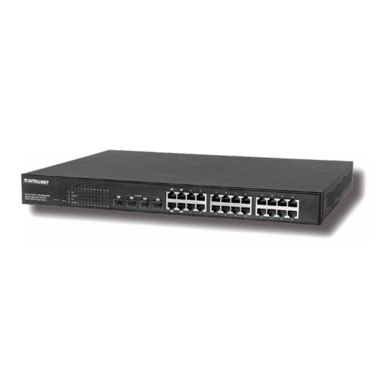
2. Hardware Description This section primarily presents the hardware of the switch, physical dimensions, appearance, front panel, rear panel and LED indicators. 2.1 Dimensions 45 × 440 × 330 mm (H × W × D) 2.2 Appearance & Front Panel The front panel of the switch consists of 24 gigabit RJ45 ports. -
Page 9: Led Indicators
2.3 LED Indicators The LED Indicators present real-time information of systematic operation status. This table provides description of LED status and the meaning. Table 1-1 LED Indicators Status Description Power on Power Switched to Off or disconnected from power source Link Link / ACT Flashing... - Page 10 SFP Installation When using the SFP ports, make sure the SFP types are compatible in terms of transmission distance, wavelength and fiber cable can meet your request. When connecting an SFP transceiver, plug in the SFP fiber transceiver first. The SFP transceiver has two plugs for fiber cable: one is TX (transmit);...
-
Page 11: Preparation For Web Interface
3. Preparation for Web Interface The Web management page allows you to use a standard Web browser — such as Microsoft Internet Explorer, Google Chrome or Mozila Firefox — to configure and interrogate the switch from anywhere on the network. Before you attempt to use the Web user interface to manage switch operation, verify that your switch is properly installed on your network and that every PC on this network can access the switch via the Web browser. - Page 12 Login Screen The factory default password is no password: Just click Apply to log in directly. Once the login is complete, the interface displays “Password successfully entered.” Note: To help ensure your switch’s security, go to the System Configuration page and set up a new password.
-
Page 13: Web Ui Configuration
4. Web UI Configuration This part instructs you how to set up and manage the switch through the Web user interface. 4.1 Configuration This section shows how to configure the switch settings. 4.1.1 System Configuration What follows is system configuration information. ... - Page 14 DHCP Enabled: Click the box to enable DHCP Client mode. Fallback IP address: Manually assign the IP address that the network is using. The default IP is 192.168.2.1. Fallback Subnet Mask: Assign the subnet mask to the IP address. ...
-
Page 15: Ports
SNMP Read Community: A community string that acts like a password and permits access with Read privilege to the SNMP database on this switch. Authorized management stations are only able to retrieve MIB objects. SNMP Write Community: A community string that acts like a password and permits access with Write privilege to the SNMP database on this switch. -
Page 16: Vlan
4.1.3 VLAN A Virtual LAN (VLAN) is a logical network grouping that limits the broadcast domain, which would allow you to isolate network traffic so only the members of the same VLAN will receive traffic from each other. Basically, creating a VLAN from a switch is logically the equivalent of reconnecting a group of network devices to another Layer 2 switch. - Page 17 VLAN ID: ID of a configured VLAN (1-4094, no leading zeroes). Enter the new ID and click Add. The Web UI is directed to the VLAN Setup screen. VLAN Configuration List: Lists all the current VLAN groups created for this system (up to 16).
-
Page 18: Aggregation
4.1.4 Aggregation Port trunk allows multiple links to be bundled together and act as a single physical link for increased throughput. It provides load balancing and redundancy of links in a switched internetwork. Actually, the link does not have an inherent total bandwidth equal to the sum of its component physical links. -
Page 19: Rstp
this administrative key is not set when an LAG is formed (i.e., it has the null value of 0), this key will automatically be set to the same value as that used by the LAG. 4.1.6 RSTP IEEE 802.1w Rapid Spanning tree protocol (LACP) provides a loop-free network and redundant links to the core network with rapid convergence to ensure faster recovery from failed links, enhancing overall network stability and reliability. - Page 20 Hello Time: Interval (in seconds) at which the root device transmits a configuration message (BPDU frame). Number between 1 and 10 (default is 2). Max Age: The maximum time (in seconds) a device can wait without receiving a configuration message before attempting to reconfigure.
-
Page 21: 802.1X Configuration
4.1.7 802.1X Configuration IEEE802.1X provides a security standard for network access control, especially in Wi-Fi wireless networks. 802.1X holds a network port disconnected until authentication is completed. The switch uses Extensible Authentication Protocol over LANS to exchange authentication protocol client identity with the client, and forward it to another remote RADIUS authentication server to verify access rights. - Page 22 The RADIUS servers make the network a lot easier to manage for the administrator by gathering and storing the user lists. Mode: By default, 802.1x is disabled. To use EAP for security, select enabled and set the 802.1X Global Settings for the Radius Server and applicable authentication information. ...
-
Page 23: Igmp Snooping
4.1.8 IGMP Snooping IGMP Snooping is the process of listening to IGMP network traffic. IGMP Snooping, as implied by the name, is a feature that allows a Layer 2 switch to “listen in” on the IGMP conversation between hosts and routers by processing the Layer 3 IGMP packets sent in a multicast network. -
Page 24: Mirroring
4.1.9 Mirroring Port Mirroring is used on a network switch to send a copy of network packets seen on one switch port (or an entire VLAN) to a network monitoring connection on another switch port. This is commonly used for network appliances that require monitoring of network traffic, such as an intrusion-detection system. -
Page 25: Qos
4.1.10 QoS In QoS Mode, select QoS Disabled, 802.1p or DSCP to configure the related parameters. QoS Mode: QoS Disabled When the QoS Mode is set to QoS Disabled, the QoS is disabled. QoS Mode: 802.1p Packets are prioritized using the 802.1p field in the VLAN tag. This field is three bits long, representing the values 0 - 7. - Page 26 QoS Mode: DSCP DSCP: Packets are prioritized using the DSCP (Differentiated Services Code Point) value. The DSCP is a six-bit field that is contained within an IP (TCP or UDP) header. The six bits allow the DSCP field to take any value in the range 0 - 63. When QoS Mode is set to DSCP, the DSCP Configuration table is displayed, allowing you to map each of the DSCP values to a hardware output queue (low, normal, medium or high).
-
Page 27: Filter Configuration
Queue Mode: Strict: Services the egress queues in sequential order, transmitting all traffic in the higher-priority queues before servicing lower-priority queues. WRR: Weighted Round-Robin shares bandwidth at the egress ports by using scheduling weights with default values of 1, 2, 4, 8 for queues 0 through 7, respectively. (This is the default selection.) * Note: WRR can only be selected if Jumbo Frame mode is disabled on the Port Configuration screen. -
Page 28: Rate Limit Configuration
PD Class: Detect the class of PD. Delivering Power (W): Output power from the switch to the PD. Current (mA): The status of the port current. Power Budget [%] ( Per 8 port total power = 130W): You can see the percentage change on this screen. -
Page 29: Storm Control
4.1.14 Storm Control Broadcast storms may occur when a device on your network is malfunctioning, or if application programs are not well designed or properly configured. If there is too much broadcast traffic on your network, performance can be severely degraded or everything can come to complete halt. - Page 30 Enable Rate Limit: Click the check box and the rate to enable storm control. Rate (number of frames per second): The Rate field is set by a single drop-down list. The same threshold is applied to every port on the switch. When the threshold is exceeded, packets are dropped, regardless of the flow-control settings.
-
Page 31: Monitoring
4.2 Monitoring 4.2.1 Statistics Overview Statistic Overview for all ports You can mirror traffic from any source port to a target port for real-time analysis. The following figures show the Statistics Overview. 4.2.2 Detailed Statistics To view the statistics of individual ports, click one of the linked port numbers for details. Clear: To renew the details collected and displayed. -
Page 32: Lacp Status
4.2.3 LACP Status LACP Aggregation Overview LACP allows for the automatic detection of links in a Port Trunking Group. Port: The port number. Port Active: Shows if the port is a member of an active LACP group. Partner Port Number: A list of the ports attached at the remote end of this LAG link member. -
Page 33: Igmp Status
Hello Time: Interval (in seconds) at which the root device transmits a configuration message. Max Age: The maximum time (in seconds) a device can wait without receiving a configuration message before attempting to reconfigure. All device ports (except for designated ports) should receive configuration messages at regular intervals. -
Page 34: Veriphy
VLAN ID: VLAN ID number. Querier: Shows whether Querying is enabled. Queries transmitted: Shows the number of transmitted Query packets. Queries received: Shows the number of received Query packets. v1 Reports: Shows the number of received v1 Report packets. ... -
Page 35: Ping
4.2.6 Ping This command sends ICMP echo request packets to another node on the network. Ping Parameters Target IP Address: IP address of the host. Count: Number of packets to send. (Range: 1-20) Time Out: Sets the time period the host will be pinged. Use the ping command to see if another site on the network can be reached. -
Page 36: Maintenance
4.3 Maintenance 4.3.1 Warm Restart Click Yes to restart the switch. The reset will be complete when the power lights stop blinking. 4.3.2 Factory Default Forces the switch to restore the original factory settings. To reset the switch, select “Reset to Factory Defaults”... -
Page 37: Configuration File Transfer
The “Software successfully loaded” message allows you to activate the new software. After you click Yes, the following message displays. 4.3.4 Configuration File Transfer Configuration File Transfer allows you to save the switch’s current configuration or restore a previously saved configuration back to the device. - Page 38 37 ...
-
Page 39: Specifications
Revision History Edition Date Modifications V1.1 Jan. 31, 2013 Update the product information. Revise the Web GUI description of the features. Add revision history 5. Specifications Standards • I EEE 8 02.1d ( Spanning T ree P rotocol) • ... - Page 40 • S witch a rchitecture: s tore a nd f orward • C onfiguration O ptions: -‐ P ort l ink s peed: 1 0 M bps, 1 00 M bps, 1 000 M bps o r a uto-‐negotiation -‐ ...
Need help?
Do you have a question about the 560900 and is the answer not in the manual?
Questions and answers