
Related Manuals for Intellinet 560665


Summary of Contents for Intellinet 560665
- Page 1 8-PORT P WEB-MANAGED DESKTOP GIGABIT SWITCH USER MANUAL MODEL 560665 intellinet-network.com INT-560665-UM-0114-02...
- Page 2 FCC Warning This Equipment has been tested and found to comply with the limits for a Class-A digital device, pursuant to Part 15 of the FCC rules. These limits are designed to provide reasonable protection against harmful interference in a residential installation. This equipment generates, uses, and can radiate radio frequency energy.
-
Page 3: Table Of Contents
Content Content Introduction Hardware Description User Log In Administrator Port Management VLAN Setting Per Port Counter QoS Setting Security Spanning Tree Trunking Backup/Recovery Miscellaneous (IGMP) Logout 1 ... -
Page 4: Introduction
Introduction Product Overview This 8 ports 10/100 Mbps high power PoE+ web-smart switch includes auto-MDI/MDIX crossover detection function. 8 of those ports are all built with PoE+ functionality, providing the ultimate choice in network flexibility. With this added PoE+ feature, this switch is an ideal solution for building wireless, IP surveillance, and VoIP networks. - Page 5 TCP/UDP Port filtering Spanning Tree Protocol STP Bridge Settings STP Port Settings Backup Recovery Configuration Miscellaneous IGMP Snooping V1/V2 Specifications Standard IEEE 802.3 10BaseT IEEE 802.3u 100BaseTX IEEE 802.3x Full-duplex and Flow Control IEEE 802.af PoE+ IEEE 802.at High power PoE+ IEEE 802.3ad Link Aggregation IEEE 802.1d Spanning tree protocol...
- Page 6 Performance MAC Address: 4K Buffer Memory: 1.625Mb Transmission Method: Store and Forward Package Contents Before you start to install this switch, please verify your package that contains the following items: One Fast Ethernet PoE+ Switch One Power Cord ...
-
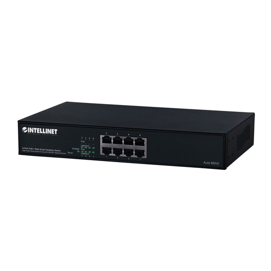
Page 7: Hardware Description
Hardware Description This section mainly describes the hardware of the 8 PoE+ port Ethernet Combo Web-Smart Switch and gives a physical and functional overview on the certain switch. Physical Dimensions/ Weight 260 × 160 × 44 mm (L × W × H) / 1.6kg Front Panel The front Panel of the Web Managed Switch consists of 8 10/100Base-TX RJ-45 ports. -
Page 8: Rear Panel
Rear Panel The 3-pronged power plug is placed at the rear panel of the switch right side shown as below. Hardware Installation Set the switch on a large flat space with a power socket close by. The flat space should be clean, smooth, level and sturdy. Make sure there is enough clearance around the switch to allow attachment of cables, power cord and allow air circulation. -
Page 9: User Log In
User Log In This part instructs user how to set up and manage the switch through the web user interface. Please follow the description to understand the procedure. At the first, open the web browser, and go to 192.168.2.1 site then the user will see the login screen. -
Page 10: Administrator
Administrator Authentication Configuration This page shows authentication configuration information. User can set new Username and Password in this page. Figure 1-3 System IP Configuration This page shows system configuration including the current IP address and sub-net mask and gateway. Figure 1-4 User can configure the IP settings, Subnet Mask, Gateway as below: ... - Page 11 gateway is 192.168.2.254 If you change the IP address of this switch and then press Update. It will show “update successfully” then press Reboot button. It will enter user login screen automatically System Status This page displays the information about the switch of MAC address, how many ports it has, system version and.
- Page 12 Load Default Setting Clicking the Load button will make the switch being set to the original configuration. Figure 1-6 ※ Note: It exclude to change user name, password and IP configuration. If you want to restore default setting including IP and user name password, then you can press the reset button for hardware base reset.
- Page 13 Firmware Update Before the firmware update procedure is executed, you should enter the password twice and then press Update button. The smart switch will erase the flash memory. There is a self-protection mechanism in the Boot Loader, so the Boot Loader will keep intact. Even though the power is turned off or the cable link fails during the firmware update procedure, the Boot loader will restore the code to firmware update page.
- Page 14 Reboot Device Click Confirm button to reboot the device. Figure 1-9 ※Note: The reboot is for software base instead of hardware base. 12 ...
-
Page 15: Port Management
Port Management Port Management includes Port Configuration, Port Mirroring, Bandwidth Control, Broadcast Storm Control and PoE+ Port Configuration In Port Configuration, you can set and view the operation mode for each port. Figure 2-1 Auto-Negotiation: Enable and Disable. Being set as ‘Enable’, the Speed, Duplex mode, Pause, Backpressure, TX Capability and Address Learning are negotiated automatically. - Page 16 Current Status: Displays current port status. Setting Status: Displays current status. Click Update to make the configuration effective. Port Mirroring The Port mirroring is a method for monitoring traffic in switched networks. That Traffic through ports can be monitored by any of the ports means traffic goes in or out monitored (source) ports will be duplicated into mirroring (destination) port.
- Page 17 Figure 2-3 Broadcast Storm Control The switch implements a broadcast storm control mechanism. Tick the check boxes to have them beginning to drop incoming broadcast packets if the received broadcast packet counts reach the threshold defined. Each port’s broadcast storm protection function can be enabled individually by ticking the check boxes.
- Page 18 Figure 2-5 16 ...
-
Page 19: Vlan Setting
VLAN Setting A Virtual LAN (VLAN) is a logical network grouping that limits the broadcast domain, which would allow you to isolate network traffic, so only the members of the same VLAN will receive traffic from the ones of the same VLAN. Basically, creating a VLAN from a switch is logically equivalent of reconnecting a group of network devices to another Layer 2 switch. - Page 20 Only packets of the VLAN Group the Port is member of will be sent. VLAN Member The ports need to be made member of your VLAN groups. This is for Tag Based and Port Based VLAN Mode. The screen here looks different whether you run Tag Based or Port Based Mode.
- Page 21 be displayed at the bottom of the screen. With the PVID Setting you define to which VLAN group incoming traffic belongs. Consider the example that Port 1 is member of group 100 and 101. A simple PC is connected to Port 1. If that PC is now sending out data, with PVID you define if that data is for group 100 or 101.
- Page 22 Multi to 2 Setting Multi to 2 VLAN is used in CPE side of Ethernet-to-the-Home and is exclusive to VLAN setting on VLAN Member Setting. When VLAN member Setting is updated, multi to 2 setting will be void and vice versa. The disable port means the port which will be excluded in this setting.
-
Page 23: Per Port Counter
Per Port Counter Port Counter This page provides port counter of each port. There are 4 categories: Receive Packet & Transmit Packet/ Transmit & Collision / Receive Packet & Drop /Receive & CRC error. Once you change the counter category, the counter will be cleared automatically. -
Page 24: Qos Setting
QoS Setting Here you can configure QoS policy priority mode and CoS (Class of Service) configuration. QoS (Quality of Service) refers to mechanisms in the network software that make the actual determination of which packets have priority. CoS refers to feature sets, or groups of services, that are assigned to users based on company policy. - Page 25 Port, 802.1p, IP/DS based Figure 4-2 23 ...
-
Page 26: Security
Security MAC Address Binding Figure 5-1 Port No: Displays the port number being assigned the MAC addresses. MAC Address: Users can assign up to 3 MAC addresses to the port. Read: Pull down the selection bar to choose a port number and click the read button to show the MAC addresses bound with the port or modify the MAC addresses. -
Page 27: Spanning Tree
Spanning Tree STP Bridge Settings Figure 6-1 Bridge Priority: This parameter configures the spanning tree priority globally for this switch. The device with the highest priority becomes the STP root device. However, if all devices have the same priority, the device with the lowest MAC address will then become the root device. - Page 28 STP Port Settings Figure 6-2 Port No: The port ID. It cannot be changed. Aggregations mean any configured trunk group. Root Path Cost: This parameter is used by the STP to determine the best path between devices. Therefore, lower values should be assigned to ports attached to faster media, and higher values assigned to ports with slower media.
-
Page 29: Trunking
Trunking Port trunk allows multiple links to be bundled together and act as a single physical link for increased throughput. It provides load balancing, and redundancy of links in a switched inter-network. Actually, the link does not have an inherent total bandwidth equal to the sum of its component physical links. -
Page 30: Backup/Recovery
Backup/Recovery This function provides the user with a method to backup/recovery the switch configuration. The user can save configuration file to a specified file. If the user wants to recover the original configuration, which is saved at the specified path, just enter the password and then press the “upload”... -
Page 31: Miscellaneous (Igmp)
Miscellaneous Miscellaneous setting is used to configure output queue aging time, VLAN stride and IGMP snooping. Figure 9-1 Output queue aging: This function is used to avoid the poor utilization of the switch. When a packet is stored in a switch for a long time, it will expire from the allowable time defined by the protocol and become a useless packet. -
Page 32: Logout
Logout The administrator has write access for all parameters governing the onboard agent. User should therefore assign a new administrator password as soon as possible, and store it in a safe place. ...
Need help?
Do you have a question about the 560665 and is the answer not in the manual?
Questions and answers