Intellinet 560559 User Manual
Web smart managed switches
Hide thumbs
Also See for 560559:
- User manual (104 pages) ,
- Instructions manual (16 pages) ,
- Quick install manual (13 pages)

Related Manuals for Intellinet 560559


Summary of Contents for Intellinet 560559
- Page 1 Web Smart Managed Switches User Manual Models 560559, 561167, 561198, 561341, 561426, 508834 intellinet-network.com...
-
Page 2: Table Of Contents
CHAPTER 1 - PRODUCT INTRODUCTION ......................5 PRODUCT OVERVIEW ......................5 FEATURES ..........................5 EXTERNAL COMPONENT DESCRIPTION ................6 1.3.1 FRONT PANEL (EXAMPLE SHOWN FROM 560559) ............6 1.3.2 REAR PANEL (19 RACKMOUNT/DESKTOP EXAMPLE SHOWN) ........7 ENVIRONMENT ........................8 PACKAGE CONTENTS ......................8 CHAPTER 2 - INSTALLING AND CONNECTING THE SWITCH ................9... - Page 3 Web Smart Managed PoE Switches User Manual 4.2.1.3 STATIC VLAN ........................32 4.2.2 MAC ADDRESS FORWARDING..................33 4.2.3 LOOPBACK DETECTION (PART OF OUR SELF-HEALING NETWORK SUITE OF FEATURES) 4.2.4 SPANNING TREE PROTOCOL (PART OF OUR SELF-HEALING NETWORK SUITE OF FEATURES) ............................ 36 4.2.4.1 SPANNING TREE PROTOCOL STATUS...................
- Page 4 Web Smart Managed PoE Switches User Manual 4.2.20.1 LLDP STATUS ........................73 4.2.20.2 LLDP SETTING ........................74 4.2.21 AAA ..........................74 4.2.21.1 802.1X ..........................75 4.2.21.2 DOMAIN ..........................77 4.2.21.3 SET AUTHENTICATION ......................78 4.2.21.4 TACACS+ SERVER SETUP ...................... 78 4.2.21.5 RADIUS SERVER SETUP ......................
-
Page 5: Chapter 1 - Product Introduction
Web Smart Managed PoE Switches User Manual Chapter 1 - Product Introduction Thank you for purchasing this Intellinet Web Smart Managed Switch. Before you install and use this product, please read this manual carefully to benefit from the full set of features that are available. -
Page 6: External Component Description
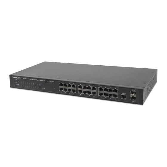
1.3 External Component Description 1.3.1 Front Panel (Example shown from 560559) Depending on your model number, the front panel of the Switch consists of up to 24 x 10/100/1000 Mbps RJ45 ports, 4 x 1000 Mbps SFP ports (and 4 x Uplink RJ45 ports), 1 x Console port, 1 x Reset button and a series of LED indicators as shown as below. -
Page 7: Rear Panel (19 Rackmount/Desktop Example Shown)
Web Smart Managed PoE Switches User Manual The following chart shows the LED indicators of the Switch along with explanation of each indicator. COLOR STATUS STATUS DESCRIPTION Power On Power Green Power Off Orange A device is connected to the port LINK/ACT/ (10/100 Mbps) -
Page 8: Environment
Web Smart Managed PoE Switches User Manual 1.4 Environment ➢ Operating Temperature: 0°C – 45°C ➢ Storage Temperature: -40°C – 70°C ➢ Operating Humidity: 10% – 90% non-condensing ➢ Storage humidity: 5% – 90% non-condensing 1.5 Package Contents Before installing the Switch, make sure that the following the packing list matches the items in the packaging. -
Page 9: Chapter 2 - Installing And Connecting The Switch
Web Smart Managed PoE Switches User Manual Chapter 2 - Installing and Connecting the Switch This part describes how to install this Switch and make connections to it. Please read the following topics and perform the procedures in the order being presented. 2.1 Installation (19 Rackmount &... -
Page 10: Desktop Installation
Web Smart Managed PoE Switches User Manual Rack Installation 2.1.2 Desktop Installation If users are not equipped with a 19-inch standard cabinet, install the Switch on a desktop. Attach the included rubber feet on the bottom of the Switch at each corner to minimize external vibration. -
Page 11: Din Rail Installation
Web Smart Managed PoE Switches User Manual 2.1.3 DIN Rail Installation For Industrial Models, the Switch can be installed onto a DIN rail. Follow these instructions: With the DIN-rail bracket attached to the device with screws, angle the bracket onto the DIN rail. Push in the device until it clicks into place. -
Page 12: Connect Computer (Nic) To The Switch
Web Smart Managed PoE Switches User Manual 2.2 Connect Computer (NIC) to the Switch After installing the network card driver, insert the NIC into the computer. Connect one end of the twisted pair to the RJ45 jack on your computer, and connect the other end to any RJ45 port of the Switch, with a maximum distance of 100 meters between the Switch and the computer. -
Page 13: Chapter 3 - How To Log Into The Switch
Web Smart Managed PoE Switches User Manual Chapter 3 - How to Log into the Switch 3.1 Switch to End Node Use standard Cat5 and higher Ethernet cable (UTP/STP) to connect the Switch to end nodes as described below. Switch ports will automatically adjust to the characteristics (MDI/MDI-X, speed, duplex) of the device to which is connected. - Page 14 Web Smart Managed PoE Switches User Manual Check whether the IP address of the computer is within this network segment: 192.168.2.xxx (xxx ranges 2 – 254), for example, 192.168.2.100. Open the browser and enter http://192.168.2.1 and then press Enter. The Switch login window appears with the following picture: Enter the Username and Password.
-
Page 15: Chapter 4 - Web Configuration Guide
Web Smart Managed PoE Switches User Manual Chapter 4 - Web Configuration Guide The Switch configuration interface consists of three main areas: the status bar at the top, the left function menu bar, and the main configuration window. Select the different functions in the function menu bar to modify all settings in the main configuration window. -
Page 16: System Info
Web Smart Managed PoE Switches User Manual 4.1.1 System Info To view the basic information of System and configure the IP address and System name, select Basic Setting>System Information settings in the function menu bar. 【Parameter Description】 Parameter Description Product description Brief description of device type Software version Show switch’s current software version. -
Page 17: General Setup
Web Smart Managed PoE Switches User Manual 4.1.2 General Setup To view the basic information of Switch, such as System Description and so on, select Basic Setting>General Setup in the function menu bar. You can also modify the System name, System contact and System location. 【Parameter Description】... -
Page 18: Ip Setup
Web Smart Managed PoE Switches User Manual 4.1.3 IP Setup To configure the IP, select Basic Setting>IP Setup in the function menu bar. 4.1.3.1 VLAN interface To configure the VLAN Interface, select Basic Setting>IP Setup>Vlan interface in the function menu bar. 【Parameter Description】... -
Page 19: Vlan Interface Config
Web Smart Managed PoE Switches User Manual 4.1.3.2 VLAN Interface Config To adjust settings to the VLAN Interface Configuration, select Basic Setting>IP Setup>Vlan Interface Config in the function menu bar. 【Parameter Description】 Parameter Description Interface name Name of interface Vlan ID Specify the VLAN ID IP Address The IP address to log into the Switch... - Page 20 Web Smart Managed PoE Switches User Manual...
-
Page 21: Port Setup
Web Smart Managed PoE Switches User Manual 4.1.4 Port Setup To configure the related parameters of a port, select Basic Setting>Port Setup in the function menu bar. 【Parameter Description】 Parameter Description Port Port number Status Choose whether to enable or disable the link port Status: Link down... - Page 22 Web Smart Managed PoE Switches User Manual Parameter Description auto-100 10/100/1000 Mbps ports: full-10 half-10 auto-10 full-100 half-100 auto-100 full-1000 half-1000 auto-1000 auto Choose the following kinds: auto Mode slave master Actual speed Displays the actual speed of the port Port description Describe the port.
-
Page 23: Dhcp Server
Web Smart Managed PoE Switches User Manual 4.1.5 DHCP Server To configure the DHCP server pool and DHCP server group, select Basic Setting>DHCP Server in the function menu bar. -
Page 24: Dhcp Server Pool Set
Web Smart Managed PoE Switches User Manual 4.1.5.1 DHCP server pool set To configure DHCP Server pool set, select Basic Setting>DHCP server>DHCP server pool set in the function menu bar. 【Parameter Description】 Parameter Description ip pool IP pool ID name Set the name of IP pool lease time Set lease time... -
Page 25: Dhcp Server Group Set
Web Smart Managed PoE Switches User Manual 4.1.5.2 DHCP server group set To configure the DHCP Server group, select Basic Setting>DHCP server>DHCP server group set link to the right of the header. 【Parameter Description】 Parameter Description group id Provide the DHCP server group ID IP address Provide the DHCP server IP address 4.1.6... -
Page 26: Port Information
Web Smart Managed PoE Switches User Manual 4.1.7 Port Information To view port information, select Basic Setting>Port Information in the function menu bar. -
Page 27: Advanced Application
Web Smart Managed PoE Switches User Manual 4.2 Advanced Application Choose Advanced Application, and the function menu bar shows configuration web pages for VLAN, MAC Address Forwarding, Loopback Detection, Spanning Tree Protocol, Bandwidth Control, Broadcast Storm Control, Mirroring, Link Aggregation, PoE Settings, PoE Scheduling, PDM, Classifier, Policy Rule, Queuing Method, Multicast, IPv6 Multicast, Dos attack protect, DHCP Snooping Setting, SNTP Setting, LLDP Protocol, AAA, EEE, ARP Safeguarding, Port Isolation, MTU, and Watch Dog. -
Page 28: Vlan
Web Smart Managed PoE Switches User Manual 4.2.1 VLAN To configure VLAN, select Advanced Application>VLAN in the function menu bar. 【Information】 Traditional Ethernet uses a common communication medium and is based on Carrier Sense Multiple Access/Collision Detect (CSMA/CD) data network communication protocol. -
Page 29: Vlan Status
Web Smart Managed PoE Switches User Manual 4.2.1.1 VLAN Status To view VLAN status, select Advanced Application>VLAN>VLAN Status in the function menu bar. 【Parameter Description】 Parameter Description VLAN Status View all VLANs configured in the device VLAN Search by VID Enter VID to view the specified VLAN 【Configuration example】... -
Page 30: Vlan Port Settings
Web Smart Managed PoE Switches User Manual 4.2.1.2 VLAN Port Settings To configure or adjust settings related to a VLAN port, select Advanced Application>VLAN>VLAN Port Settings in the function menu bar. 【Parameter Description】 Parameter Description PVID (Port VLAN The PVID of the port can be modified, the default port PVID is Choose the following kinds: Acceptable Frame Tagged only... - Page 31 Web Smart Managed PoE Switches User Manual Parameter Description Hybrid: The port can be either a tagged member or untagged member in the VLAN and can be a member port for multiple VLANs. Used to connect switches to each other and to computers.
-
Page 32: Static Vlan
Web Smart Managed PoE Switches User Manual 4.2.1.3 Static VLAN To configure a Static VLAN, select Advanced Application>VLAN>Static VLAN in the function menu bar. 【Parameter Description】 Parameter Description VLAN List VLAN group ID Name VLAN group name 【Configuration example】 To add and delete VLAN members: Click Advanced Application >... -
Page 33: Mac Address Forwarding
Web Smart Managed PoE Switches User Manual 4.2.2 MAC Address Forwarding To configure MAC Address Forwarding, select Advanced Application>MAC Address Forwarding in the function menu bar. 【Parameter Description】 Parameter Description MAC Type: Static MAC MAC Type Dynamic MAC Blackhole MAC Permanent MAC 【Information】... - Page 34 Web Smart Managed PoE Switches User Manual Unknown source MAC packet drop settings. Click Modify.
-
Page 35: Loopback Detection (Part Of Our Self-Healing Network Suite Of Features)
Web Smart Managed PoE Switches User Manual 4.2.3 Loopback Detection (Part of our Self-Healing Network Suite of Features) To configure Loopback Detection, select Advanced Application>Loopback Detection in the function menu bar. Loopback Detection allows the switch to detect loops in the network. - Page 36 Web Smart Managed PoE Switches User Manual 4.2.4 Spanning Tree Protocol (Part of our Self-Healing Network Suite of Features) To configure Spanning Tree Protocol (STP), select Advanced Application>Spanning Tree Protocol in the function menu bar. According to the IEEE 802.1D standard, STP is used to create ring-free networks on the Data Link layer in a local network.
-
Page 37: Spanning Tree Protocol Status
Web Smart Managed PoE Switches User Manual 4.2.4.1 Spanning Tree Protocol Status To view Spanning Tree Protocol status, select Advanced Application>Spanning Tree Protocol>Spanning Tree Protocol Status in the function menu bar. 【Parameter Description】 Parameter Description Root Path Cost Configure Root Path Cost Send Bridge Protocol Data Unit (BPDU) in Hello time (second) packet interval... -
Page 38: Spanning Tree Configuration
Web Smart Managed PoE Switches User Manual 4.2.4.2 Spanning Tree Configuration To configure Spanning Tree, select Advanced Application>Spanning Tree Protocol>Spanning Tree configuration in the function menu bar. 【Parameter Description】 Parameter Description Spanning tree mode: IEEE Compatible Spanning Tree Spanning Tree Mode Rapid Spanning Tree Multiple Spanning Tree Global Spanning... -
Page 39: Compatible/Rapid Spanning Tree Protocol
Web Smart Managed PoE Switches User Manual 4.2.4.3 Compatible/Rapid Spanning Tree Protocol To configure Compatible/Rapid Spanning Tree Protocol, select Advanced Application>Spanning Tree Protocol>Compatible/Rapid Spanning Tree Protocol in the function menu bar. 【Parameter Description】 Parameter Description Bridge Priority Set bridge priority, the default instance bridge priority for 32768 Hello Time Send Bridge Protocol Data Unit (BPDU) in packet interval The time the switch will wait before initiating topology changes... - Page 40 Web Smart Managed PoE Switches User Manual 【Configuration example】 As shown in the figure, configure Switch-A as the root bridge and S-switch-B as the designated Bridge. The links connected by S-switch-B and S-switch-C are backup links. When the links connected by S-switch-B, S-switch-A and S-switch-C fail, the backup link will come into effect.
-
Page 41: Multiple Spanning Tree Protocol
Web Smart Managed PoE Switches User Manual 4.2.4.4 Multiple Spanning Tree Protocol To configure Multiple Spanning Tree Protocol, select Advanced Application>Spanning Tree Protocol>Multiple Spanning Tree Protocol in the function menu bar. 【Parameter Description】 Parameter Description Hello Time Send BPDU in packet interval The time the switch will wait before initiating topology Max age changes for ports that have not received a message... -
Page 42: Bandwidth Control
Web Smart Managed PoE Switches User Manual Parameter Description Set the maximum number of hops that BPDUs can Maximum Hops support in the spanning tree Configuration Name Fill in configuration name Revision Number Set revision number Instance Instance number Priority setting bridge example, the default instance Bridge Priority bridge priority for 32768 VLAN Range... -
Page 43: Broadcast Storm Control
Web Smart Managed PoE Switches User Manual 【Configuration example】 Configure bandwidth control for port 8. Click Basic Setting > Bandwidth Control. Configure port-8 Ingress Rate as 64 kbps and the Egress Rate as 128 kbps. Click Apply. 4.2.6 Broadcast Storm Control To configure Broadcast Storm Control, select Advanced Application>Broadcast Storm Control in the function menu bar. - Page 44 Web Smart Managed PoE Switches User Manual Parameter Description Multicast rate limitation (the range of 64 - 32000000, unit: pps; Multicast you must enter a multiple of 64, default is 49984) Unicast rate limitation (the range of 64 - 32000000, unit: pps; Unicast you must enter a multiple of 64, default is 49984) 【Information】...
-
Page 45: Mirroring
Web Smart Managed PoE Switches User Manual 4.2.7 Mirroring To configure mirroring, select Advanced Application>Mirroring in the function menu bar. 【Parameter Description】 Parameter Description Active Select to enable or disable Mirroring Set up the monitoring port and forward the flow data of the Monitor Port source port to the message analyzer to analyze the message and then forward to the monitoring port... - Page 46 Web Smart Managed PoE Switches User Manual...
-
Page 47: Link Aggregation
Web Smart Managed PoE Switches User Manual 4.2.8 Link Aggregation To configure link aggregation, select Advanced Application>Link Aggregation in the function menu bar. With the LAG (Link Aggregation Group) function enabled, you can aggregate multiple physical ports into a logical interface to increase link bandwidth and configure the backup ports to enhance the connection reliability. -
Page 48: Link Aggregation Setting
Web Smart Managed PoE Switches User Manual 4.2.8.2 Link Aggregation Setting To set Link Aggregation, select Advanced Application>Link Aggregation>Link Aggregation Setting in the function menu bar. 【Parameter Description】 Parameter Description Group ID Add the port to the specified Aggregation Group ID Port LACP mode Configure port aggregation (active/passive) -
Page 49: Link Aggregation Control Protocol
Web Smart Managed PoE Switches User Manual 4.2.8.3 Link Aggregation Control Protocol To configure Link Aggregation Control Protocol, select Advanced Application>Link Aggregation>Link Aggregation Control Protocol in the function menu bar. 【Parameter Description】 Parameter Description Aggregation group system priority, the default is System priority 32768 (the range is 1 - 65535) Load-balance... -
Page 50: Poe Settings (Excludes 508834, Where Poe Is Not Supported)
Web Smart Managed PoE Switches User Manual 4.2.9 PoE Settings (excludes 508834, where PoE is not supported) To adjust settings for PoE, select Advanced Application>PoE Settings. 4.2.9.1 PoE Settings To configure PoE, select Advanced Application>PoE Settings. 【Parameter Description】 Parameter Description power limit Set the limit for the overall power of PoE switch... -
Page 51: Poe Port Settings
Web Smart Managed PoE Switches User Manual 4.2.9.2 PoE Port Settings To configure settings for a PoE Port, select Advanced Application>PoE Settings>PoE Port Settings in the function menu bar. 【Parameter Description】 Parameter Description Enable Turn the port PoE power on and off; the default is enabled Configure IEEE 802.3af or IEEE 802.3at mode;... -
Page 52: Poe Scheduling (Part Of Our Self-Healing Network Suite Of Features)
Web Smart Managed PoE Switches User Manual 4.2.10 PoE Scheduling (Part of our Self-Healing Network Suite of Features) To configure PoE Scheduling, select Advanced Application>PoE Scheduling. 4.2.10.1 PoE Scheduling To configure PoE Scheduling, select Advanced Application>PoE Scheduling. 【Parameter Description】 Parameter Description Range Name Set the name for the schedule... -
Page 53: Configure Port Poe Scheduling
Web Smart Managed PoE Switches User Manual 【Configuration example】 Set Range Name 1 with the values shown. 4.2.10.2 Configure Port PoE Scheduling To configure Port PoE Scheduling, select Advanced Application>PoE Scheduling>Configure Port PoE Scheduling in the function menu bar. 【Parameter Description】 Parameter Description From Port... -
Page 54: Pdm (Part Of Our Self-Healing Network Suite Of Features)
Web Smart Managed PoE Switches User Manual 4.2.11 PDM (Part of our Self-Healing Network Suite of Features) To configure the Powered Device Monitor (PDM) which restarts “down” devices, select Advanced Application>PDM. 【Parameter Description】 Parameter Description From Port Set the start port To Port Set the end port PDM State... -
Page 55: Classifier
Web Smart Managed PoE Switches User Manual 4.2.12 Classifier To configure Classifier, select Advanced Application>Classifier in the function menu bar. 【Parameter Description】 Parameter Description Action Deny or Permit Type IP or MAC Action Permit or Deny... -
Page 56: Policy Rule
Web Smart Managed PoE Switches User Manual 4.2.13 Policy Rule To configure Policy Rule, select Advanced Application>Policy Rule in the function menu bar. 【Parameter Description】 Parameter Description Active Activate Classifier Classifier(s) Note: Classification rules must match Priority Choose whether to enable priority and set priority DSCP Choose whether to enable DSCP Egress Port... -
Page 57: Queuing Method
Web Smart Managed PoE Switches User Manual 4.2.14 Queuing Method To configure queuing method, select Advanced Application>Queuing Method in the function menu bar. 【Parameter Description】 Parameter Description Five methods: Method SPQ, WRR, SP+WRR, WFQ, SP+WFQ 【Information】 ➢ Strict-Priority (SP) and Weighted Round Robin (WRR). Strict Priority Queueing... - Page 58 Web Smart Managed PoE Switches User Manual Strict Priority Queueing is specially designed to meet the demands of critical services or applications. Critical services or applications such as voice are delay-sensitive and thus require to be dequeued and sent first before packets in other queues are dequeued on a congested network.
-
Page 59: Multicast
Web Smart Managed PoE Switches User Manual 4.2.15 Multicast To configure Multicast, select Advanced Application>Multicast in the function menu bar. 4.2.15.1 Multicast Status To view all multicast, including the static configuration and the multicast that is learned through the IGMP-Snooping protocol, select Advanced Application>Multicast>Multicast Status in the function menu bar. -
Page 60: Multicast Settings
Web Smart Managed PoE Switches User Manual 4.2.15.2 Multicast Settings To set multicast, select Advanced Application>Multicast>Multicast Settings in the function menu bar. 【Parameter Description】 Parameter Description Active Enable IGMP snooping Querier Enable IGMP snooping timed query function Host Timeout Configure the dynamic group sowing time (default 300 s) IGMP Route Port Enable IGMP Route Port Forward Forward... -
Page 61: Igmp Snooping Deny Vlan
Web Smart Managed PoE Switches User Manual Parameter Description Max Group Limit Max learning group of configuration port (default 1020) Enable port quick-exit function (i.e., when the port Fast Leave receives the IGMP and leaves the message, immediately remove the port from the reshuffle group) Multicast VLAN The configuration group multicast the default VLAN The configuration port refers to the multicast preview,... -
Page 62: Igmp Filtering Profile
Web Smart Managed PoE Switches User Manual 4.2.15.4 IGMP Filtering Profile To add and remove the preview feature of the modified group, select Advanced Application>Multicast>IGMP Filtering Profile in the function menu bar. 【Parameter Description】 Parameter Description Profile ID The range of 1 - 128 Profile Limit Profile rules can be permit or deny The preview address can be configured to be either IP or... -
Page 63: Ipv6 Multicast
Web Smart Managed PoE Switches User Manual 4.2.16 IPv6 Multicast To configure IPv6 Multicast, select Advanced Application>IPv6 Multicast in the function menu bar. 4.2.16.1 IPv6 Multicast Status To view all IPv6 multicast groups, select Advanced Application>IPv6 Multicast>IPv6 Multicast Status in the function menu bar. -
Page 64: Ipv6 Multicast Setting
Web Smart Managed PoE Switches User Manual 4.2.16.2 IPv6 Multicast Setting To configure IPv6 Multicast, select Advanced Application>IPv6 Multicast>IPv6 Multicast Setting in the function menu bar. 【Parameter Description】 Parameter Description Active Enable or disable MLD snooping Querier Enable or disable MLD snooping timed Querier Host Timeout Configure Dynamic IPv6 multicast aging time (default 300s) - Page 65 Web Smart Managed PoE Switches User Manual Parameter Description MLD Route Port Enable or disable MLD Route Port Forward Forward Configure maximum learning IPv6 Multicast message Max Group Limit of port (default 1020) Enable or disable Fast Leave (That is, when the port receives Fast Leave IGMP leave message, the port is deleted immediately from the IPv6 multicast group)
-
Page 66: Mld Snooping Deny Vlan
Web Smart Managed PoE Switches User Manual 4.2.16.3 MLD Snooping Deny VLAN To configure MLD Snooping Deny VLAN, select Advanced Application>IPv6 Multicast>MLD Snooping Deny VLAN in the function menu bar. 【Parameter Description】 Parameter Description VLAN ID... -
Page 67: Dos Attack Protect
Web Smart Managed PoE Switches User Manual 4.2.17 DoS Attack Protect To configure DoS Attack Protect, select Advanced Application>Dos Attack Protect in the function menu bar. 【Parameter Description】 Parameter Description dos attack DoS attack is controlled by the discarding behavior of the control corresponding message... -
Page 68: Dhcp Snooping Setting
Web Smart Managed PoE Switches User Manual 4.2.18 DHCP Snooping Setting To configure DHCP Snooping, select Advanced Application>DHCP Snooping Setting in the function menu bar. 4.2.18.1 DHCP Snooping Setting To configure DHCP Snooping, select Advanced Application>DHCP Snooping Setting>DHCP Snooping Setting in the function menu bar. Today’s networks can be large and complicated. - Page 69 Web Smart Managed PoE Switches User Manual 【Parameter Description】 Parameter Description DHCP Snooping Enable Enable or disable DHCP Snooping Enable or disable the DHCP Snooping port trust Trust property state Maxclients Set Maxclients 【Configuration Example】...
-
Page 70: Ip Source Guard
Web Smart Managed PoE Switches User Manual 4.2.18.2 IP Source Guard To configure IP Source Guard, select Advanced Application>DHCP Snooping Setting>IP Source Guard in the function menu bar. 【Parameter Description】 Parameter Description Mode Setting the Mode (Disable, IP, IP+MAC, IP+MAC+VLAN) -
Page 71: Sntp Setting
Web Smart Managed PoE Switches User Manual 4.2.19 SNTP Setting To configure SNTP, select Advanced Application>SNTP Setting in the function menu bar. 【Parameter Description】 Parameter Description SNTP Client Enable Enable or disable SNTP Client SNTP Client Mode: SNTP Client Mode broadcast, anycast, multicast, unicast The interval that SNTP Client sends requests to the SNTP SNTP Client Poll Interval... - Page 72 Web Smart Managed PoE Switches User Manual Parameter Description SNTP Server Key Set SNTP Server Key 【Information】 SNTP Client receives and transmits messages from any SNTP Server when the work mode of the SNTP Client is broadcast or multicast. Local time cannot be synchronized to standard time if there is a malicious attack server (which provides incorrect time).
-
Page 73: Lldp Protocol
Web Smart Managed PoE Switches User Manual 4.2.20 LLDP Protocol To configure LLDP, select Advanced Application>LLDP Protocol in the function menu bar. 4.2.20.1 LLDP Status To view LLDP status, select Advanced Application>LLDP Protocol>LLDP Status in the function menu bar. -
Page 74: Lldp Setting
Web Smart Managed PoE Switches User Manual 4.2.20.2 LLDP Setting To configure LLDP, select Advanced Application>LLDP Protocol>LLDP Setting in the function menu bar. 4.2.21 To configure AAA, select Advanced Application>AAA in the function menu bar. -
Page 75: 802.1X
Web Smart Managed PoE Switches User Manual 4.2.21.1 802.1x To configure 802.1x, select Advanced Application>AAA>802.1x in the function menu bar. 【Parameter Description】 Parameter Description EAP Forwarding Mode: EAP Forwarding EAP-finish, Mode EAP-tansfer If the same user fails to log in more than the allowed Quiet Period value, he or she will not be allowed to try to log in until a certain time... - Page 76 Web Smart Managed PoE Switches User Manual Parameter Description After user authentication is passed, the port can be Reauthentication configured to require reauthentication or to periodically re-authenticate Reauthentication Time range: 10 - 3600 seconds Timer Max user(s) The maximum number of users: 1 - 100 【Configuration Example】...
-
Page 77: Domain
Web Smart Managed PoE Switches User Manual 4.2.21.2 Domain To configure RADIUS Domain, select Advanced Application>AAA> Domain in the function menu bar. 【Parameter Description】 Parameter Description Active Enable or disable RADIUS domain Domain Name Set domain name Default Domain Enable or disable Default Domain Radius Server Name Set RADIUS Server name Force Max Number... -
Page 78: Set Authentication
Web Smart Managed PoE Switches User Manual 4.2.21.3 Set Authentication To configure Remote Authentication, select Advanced Application>AAA>Set Authentication in the function menu bar. 【Parameter Description】 Parameter Description Authenication Mode: Authenication Local, Mode Radius, Tacacs+ 4.2.21.4 TACACS+ Server Setup To configure TACACS+ Server Setup, select Advanced Application>AAA>TACACS+ Server Setup in the function menu bar. -
Page 79: Radius Server Setup
Web Smart Managed PoE Switches User Manual 4.2.21.5 Radius Server Setup To configure RADIUS Server Setup, select Advanced Application>AAA>Radius Server Setup in the function menu bar. 【Parameter Description】 Parameter Description If activated and user authentication is successful, this 8021P Priority function will modify the PVID of the user's port. -
Page 80: Eee (Part Of Our Self-Healing Network Suite Of Features)
Web Smart Managed PoE Switches User Manual 4.2.22 EEE (Part of our Self-Healing Network Suite of Features) To enable or disable the function for Energy Efficient Ethernet, select Advanced Application>EEE in the function menu bar. 4.2.23 ARP Safeguarding To prevent ARP flooding, select Advanced Application>ARP Safeguarding. 【Parameter Description】... -
Page 81: Port Isolation
Web Smart Managed PoE Switches User Manual 4.2.24 Port Isolation To configure Port Isolation, select Advanced Application>Port Isolation. 4.2.25 To configure to MTU, select Advanced Application>MTU. 【Parameter Description】 Parameter Description Set MTU, range 1522 – 10240... -
Page 82: Watch Dog (Part Of Our Self-Healing Network Suite Of Features)
Web Smart Managed PoE Switches User Manual 4.2.26 4.2.26 Watch Dog (Part of our Self-Healing Network Suite of Features) To configure Watch Dog, select Advanced Application>Watch Dog. 【Parameter Description】 Parameter Description Watch Dog Status Enable or disable Watch Dog Status CPU Busy Threshold Set the CPU Busy Threshold... -
Page 83: Management
Web Smart Managed PoE Switches User Manual 4.3 Management Choose Management, and the following page appears. There are configuration web pages for Management & Maintenance, Access Control, Diagnostic and Syslog. 4.3.1 Management and Maintenance To upgrade firmware, restart the system and perform switch maintenance, select Management>... -
Page 84: Access Control
Web Smart Managed PoE Switches User Manual 4.3.2 Access Control To set SNMP and Logins, select Management>Access Control in the function menu bar. 4.3.2.1 SNMP To configure SNMP, select Management> Access Control>SNMP in the function menu bar. 【Parameter Description】 Parameter Description All Community Set All Community... -
Page 85: User Information
Web Smart Managed PoE Switches User Manual 【Configuration Example】 Add a group name public community, set access to Read-Write. Set host 192.168.2.3 to receive trap messages. The specified version is v2c. 4.3.2.2 User Information To add a user, set a Security Level, Authentication, Privacy, Group and Password, select Management>... -
Page 86: Logins
Web Smart Managed PoE Switches User Manual 【Configuration Example】 Add group initial, add username user1. 4.3.2.3 Logins To modify the admin password and configure ordinary users, select Management>Access Control>Logins in the function menu bar. 【Parameter Description】 Parameter Description User privilege 0 - 1: normal;... - Page 87 Web Smart Managed PoE Switches User Manual 【Configuration Example】...
-
Page 88: Super Password
Web Smart Managed PoE Switches User Manual 4.3.2.4 Super Password To set a Super Password, select Management>Access Control>Super Password in the function menu bar. 4.3.3 Diagnostic To display or clear the System Log, select Management> Diagnostic in the function menu bar. 【Configuration Example】... -
Page 89: Syslog
Web Smart Managed PoE Switches User Manual 4.3.4 Syslog To configure the Syslog, select Management> Syslog in the function menu bar. 4.3.4.1 Syslog Setup To start the logging function globally and the logging function of the corresponding module, select Management>Syslog>Syslog Setup in the function menu bar. 【Parameter Description】... -
Page 90: Syslog Server Setup
Web Smart Managed PoE Switches User Manual 【Configuration Example】 4.3.4.2 Syslog Server Setup To set the syslog server, select Management>Syslog>Syslog Server Setup in the function menu bar. 【Parameter Description】 Parameter Description Server Address Syslog Server Address Level 0 Level 0-1 Level 0-2 Level 0-3 Log Level... - Page 91 Web Smart Managed PoE Switches User Manual 【Information】 Open the log switch, set up the syslog server, and the system log will be automatically pushed to the server. 【Configuration Example】 Set server address to 192.168.2.100.
-
Page 92: Chapter 5 - Appendix
1000Base-SX:62.5μm/50μm MMF (2 m – 550 m) 1000Base-LX:62.5μm/50μm MMF (2 m – 550 m) or 10μm SMF (2 m – 5000 m) • 560559: 26 (24 RJ45, 2 SFP) • 561167: 10 (8 RJ45, 2 SFP) • 561198: 18 (16 RJ45, 2 SFP) Number of Ports (Total) •... - Page 93 Rate 1000 Mbps: 1488000pps • 560559: 440 (W) x 208 (L) x 44 (H) mm (17.3 x 8.19 x 1.7 in.) • 561167: 280 (W) x 180 (L) x 44 (H) mm (11.02 x 7.09 x 1.73 in.) • 561198: 440 (W) x 208 (L) x 44 (H) mm (17.32 x 8.19 x 1.73 in.) Dimensions (W x L ×...
-
Page 94: Software Specification
Web Smart Managed PoE Switches User Manual Industrial Version 508834 Operating Temperature: -40 °C – 85°C Storage Temperature: -40°C – 85°C Operating Humidity: 5% – 95% RH non-condensing Storage humidity: 5% – 95% RH non-condensing 5.1.2 Software Specification Ethernet Setup STP/RSTP/MSTP Storm-control Basic function... -
Page 95: Features And Terms Explained
Web Smart Managed PoE Switches User Manual IGMP Snooping SNMPV1, V2c, V3 RMON (1, 2, 3, 9) PoE Status PoE Management Power supply management mode(auto/energy/static) The port priority 5.2 Features and Terms Explained VLAN A Virtual Local Area Network, this allows network admins to maintain a virtual network to optimize devices attached to the switch for better overall performance. - Page 96 The ability to schedule the availability of PoE on each port of the switch on a day/time basis. Powered Device Monitoring, a function that restarts any connected PoE device that fails to respond or send out network traffic. (Configurable on Intellinet Network Solutions Managed Switches).
-
Page 97: Chapter 6 - Additional Information
Web Smart Managed PoE Switches User Manual Chapter 6 - Additional Information 6.1 WASTE ELECTRICAL & ELECTRONIC EQUIPMENT DISPOSAL OF ELECTRIC AND ELECTRONIC EQUIPMENT (Applicable In the E.U. and Other European Countries With Separate Collection Systems) ENGLISH: This symbol on the product or its être traité... -
Page 98: Warranty
6.2 WARRANTY Go to Intellinet-network.com EN MÉXICO: Póliza de Garantía Intellinet Network Solutions — Datos del importador y responsable ante el consumidor • IC Intracom México, S.A.P.I. de C.V. • Av. Interceptor Poniente # 73, Col. Parque Industrial La Joya, Cuautitlán Izcalli, Estado de México, C.P. 54730, México. • Tel. (55)1500-4500 • La presente garantía cubre los siguientes productos contra cualquier defecto de fabricación en sus... - Page 99 : Urządzenie spełnia wymagania CE 2014/30/EU I / lub 2014/35/EU. Deklaracja zgodności dostępna jest na stronie internetowej producenta: ITALIANO : Questo dispositivo è conforme alla CE 2014/30/EU e / o 2014/35/EU. La dichiarazione di conformità è disponibile al: support.intellinet-network.com/barcode/560559 support.intellinet-network.com/barcode/561167 support.intellinet-network.com/barcode/561198 support.intellinet-network.com/barcode/561341 support.intellinet-network.com/barcode/561426...
Need help?
Do you have a question about the 560559 and is the answer not in the manual?
Questions and answers