Kessel 99601.016B Installation And Operating Instructions Manual
Oil/fuel separator
Hide thumbs
Also See for 99601.016B:
Table of Contents
Advertisement
Available languages
Available languages
Quick Links
ANLEITUNG FÜR EINBAU, BEDIENUNG UND WARTUNG
KESSEL - Leichtflüssigkeitsabscheider
aus Polyethylen NS 1,5
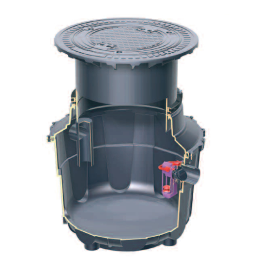
KESSEL - Öl-/Benzinabscheider
NG 1,5 zum Einbau ins Erdreich
Installation
der Anlage wurde durchgeführt von Ihrem Fachbetrieb:
Name/Unterschrift
Stand 08/2016
Inbetriebnahme
Datum
Einweisung
Ort
D
Bedienungsanleitung
GB
Seite 1-14
Installation Manual
Page 15-28
99601.002B
99601.016 B/D
99601.041.B/D
Produktvorteile
Leichte Einbringung
in die Baugrube
ohne Baukran möglich
Einfache, schnelle Montage
Recycling freundlicher
Werkstoff
Absolut wasserdicht
durch nahtlose mono -
lithische Bauweise
Bundesweites Servicenetz
Stempel Fachbetrieb
Sach-Nr. 308-100
Advertisement
Chapters
Table of Contents

Related Manuals for Kessel 99601.016B


Summary of Contents for Kessel 99601.016B
- Page 1 ANLEITUNG FÜR EINBAU, BEDIENUNG UND WARTUNG KESSEL - Leichtflüssigkeitsabscheider aus Polyethylen NS 1,5 Bedienungsanleitung Seite 1-14 KESSEL - Öl-/Benzinabscheider Installation Manual Page 15-28 NG 1,5 zum Einbau ins Erdreich 99601.002B 99601.016 B/D 99601.041.B/D Produktvorteile Leichte Einbringung in die Baugrube ohne Baukran möglich...
- Page 2 1. Sicherheitshinweise Das Personal für Einbau, Montage, Bedienung, Wartung und Reparatur muß die entspre- chende Qualifikation für diese Arbeiten aufweisen. Verantwortungsbereich, Zuständigkeit und die Überwachung des Personals müssen durch den Betreiber genau geregelt sein. Die Betriebssicherheit der gelieferten Anlage ist nur bei bestimmungsgemäßer Verwendung gewährleistet.
-
Page 3: Table Of Contents
Inhaltsverzeichnis ................. Seite 1. Sicherheitshinweise ................. Seite 2. Einsatzbereich Maßzeichnung Öl-/Benzinabscheider ...... Seite 3. Technische Daten Verpackung............... Seite Transport ..............Seite 4. Verpackung, Transport Lagerung ..............Seite und Lagerung Einbauvoraussetzungen........... Seite Verfüllmaterial ............Seite 5. Einbau und Montage Baugrube..............Seite Prüfungen vor dem Einbau ........ -
Page 4: Seite
Sehr geehrter Kunde, wir freuen uns, daß Sie sich für ein Produkt von KESSEL entschieden haben. Die gesamte Anlage wurde vor Verlassen des Werkes einer strengen Qualitätskontrolle unterzogen. Prüfen Sie bitte den- noch sofort, ob die Anlage vollständig und unbeschädigt bei Ihnen angeliefert wurde. Im Falle eines Transportschadens beachten Sie bitte die Anweisungen in Kapitel „Gewährleistungen“... -
Page 5: Seite
- mit einer Dichte bis zu 0,95g/cm möglichst kurz gehalten werden sollten. Ein spezielles Ein- - für Leichtflüssigkeiten mineralischen Ursprungs laufsystem im KESSEL Öl- / Benzinabscheider bewirkt eine - mit selbsttätigen Abschluss sogenannte Pfropfenströmung. D.h. die Strömung wird im Abscheider gleichmäßig verteilt und damit komplett hydrau- Diese Abscheideranlage gilt nicht für die Behandlung von... -
Page 6: Verpackung
(mm) (mm) (kg) 17,6 99601.002B 1091 1012 70,5 99601.016B/D 1000 1425 1300 99601.041B/D 4. Verpackung, Transport und Lagerung Die Behälter müssen so transportiert werden, daß sie nicht unzulässig belastet werden und daß eine Lageveränderung Das Kapitel Sicherheitshinweise ist zu beachten! während des Transports ausgeschlossen ist. -
Page 7: Einbauvoraussetzungen
5. Einbau und Montage Die Tiefe der Baugrube ist so zu bemessen, daß die Grenzen der Erdüberdeckung nicht überschritten werden. Während der Zwischenlagerung des Abscheiders so wie bis MIN ≤ T ≤ MAX (siehe Maßzeichnung). zum Abschluß der Einbauarbeiten müssen an der Baustelle EÜ... -
Page 8: Einbau
Klasse D) muss als oberste Schicht eine Stahlbe- 5.6 Installationshöhen für Alarmanlage tonplatte vorgesehen werden. Ein zugehöriger Schalungs- und Bewehrungsplan ist bei KESSEL erhältlich. Ist die Baugrube bis zur Unterkante der Zu- und Ablauflei - Anschluss Behälter tungs anschlüsse aufgefüllt und verdichtet, sind die Zu-/ Ab laufleitungen frostfrei zu verlegen und anzuschließen. -
Page 9: Anlage In Betriebsbereitschaft Setzen
Die Inbetriebnahme und Einweisung wird in der Regel von 5. Erstellung des Übergabeprotokolls. 6.2 Einweisung / Übergabe ei nem Fachbetrieb durchgeführt, kann aber auch auf Wunsch gegen Berechnung von einem KESSEL-Beauftrag- Nach Beendigung der Einweisung ist die Anlage wieder in ten durchgeführt werden. betriebsbereiten Zustand zu setzen. -
Page 10: Seite
8. Wartung 1. Eigenkontrolle Sachkundige Personen Bedienungsvorschriften sind in der näheren Umgebung BITTE BEACHTEN SIE: des Abscheiders anzubringen. Messung der Schichtdicke von: - Leichtflüssigkeits Der Entsorgungsvorgang ist genau nach Anweisung durchzuführen. - der Schlammschicht Die Entsorgung der Abscheideranlage nur von zu ge - Kontrolle des selbsttätigen Abschlusses und der Alarmeinrichtungen lassenen Entsorgungsunternehmen durchführen las-... - Page 11 915 813 D 1330-1660 915 823 A 915 823 B 915 823 D * Minimale Einbautiefe erreichbar durch Absägen KESSEL-Zwischenstück aus Kunststoff Art.Nr. 915 402 für vertieften Einbau. Für vertieften Einbau KESSEL-Verlängerungsstück für Probeschacht Aufstockhöhe max. 600 mm (kürzbar). Fabrikat: KESSEL Ausführung Art.Nr.
- Page 12 Kontakt, mit Fühlereigenüberwachung und Alarmwiederholung. Art.Nr. 917 801 KESSEL-Alarmanlage zur Grenzstandsanzeige des Aufstaus für Koaleszensab- Grenzstandsonde mit 5 m Anschlusskabel (bis max. 200 m verlängerbar), Befestigungs- scheider set für einfache Montage und Wartung (Sonde ist damit von oben erreichbar), wasser- dichter Kabelverbindung zum Verlängern des Anschlusskabels, Durchgangsrohr mit...
- Page 13 10. Anlagenpass / Werksabnahme...
- Page 14 Führend in Entwässerung Privater Wohnungsbau ohne Kanalanbindung 1 2 3 4 1 2 3 4 Öffentlicher Bau z.B. Krankenhaus Öffentlicher Bau z.B. Freizeitanlagen 1 2 3 4 Gewerblicher Bau z.B. Hotel Gewerblicher Bau z.B. Industriebau 2 3 5 Gewerblicher Bau z.B.
- Page 15 INSTALLATION AND OPERATING INSTRUCTIONS KESSEL – Oil/fuel separator PE Separators NS 1,5 99601.002B KESSEL - Oil/fuel separator 99601.016 B/D NS 1,5 for underground installation 99601.041.B/D Product advantages Easy on-site mobility with- out the need for heavy machinery Simple and quick installation...
- Page 16 1. Safety Precautions By installation, use, maintenance and repair of this unit please follow all appropriate DIN / VDE / DVGW safety precautions and accident prevention guidelines. Also please follow any local safety precautions and accident prevention guidelines established in your area. Also please observe the following: •...
- Page 17 Table of Contents 1. Safety instructions ..................Page 16 2. General ..................Page 19 3. Technical specifications Dimensioned drawing ............. Page 20 4. Transport and storage Transport ................Page 20 Storage ................Page 20 5. Installation and assembly Installation requirements..........Page 21 On-site earthwork ............
- Page 18 Dear Customer, Before the KESSEL Oil / Fuel separator is installed and placed in operation please carefully read and follow all of the in- structions contained in this Installation, Maintenance and User's Manual. Upon delivery of the KESSEL separator please thoroughly inspect the separator to make sure that it has not been damaged during shipping.
- Page 19 / fuel from flowing - with self actuating emergency closure float switch. out of the separator’s outlet. In KESSEL oil / fuel separator This separator is not for use for treatment of stabile emul- systems, this consists of a float switch which is installed in a guide pipe which during operation is full of water.
-
Page 20: Technical Specifications
In cases where the separator needs to be temporarily stored before installation, it is important that the separator is placed Transportation of the KESSEL separator should be handled on firm level ground and in an area where it is protected from only by a transporter who has the proper knowledge, equip- coming in contact with other objects. -
Page 21: Installation Requirements
5. Installation and assembly 5.3 Trench preparation / Backfilling During the intermediate storage of the separator and until completion of the installation work, suitable safeguarding measures must be taken at the building site to prevent ac- The sub-base of the installation trench should be a 30cm cidents and damage to the separator thick flat compacted layer of 8/16 gravel / process, Dpr = 95%). -
Page 22: Installation
/ outlet. Before installing the KESSEL upper sections be sure to insert the gasket into the recessed opening of the access shaft. Lubricated the gasket and insert the polymer upper section to the desired height / position. -
Page 23: Operation And Disposal
The separator should be returned to service by filling led by a KESSEL representative. the separator with fresh, cold water The following personnel should be on hand when the initial instructions for placing the separator into operation are given: 6.4 Hand-over of installation and user’s manual. -
Page 24: Maintenance
8. Maintenance 1. Do it yourself inspection Pleaser insure that: - Technically trained staff - Installation and User’s Manual and all relevant documen- - Measurement of: tation is placed in an accessible area near the separator. - Oil / fuel level - The disposal procedure is handle as documented - Sludge level - The disposal is handled only by a licensed professional... -
Page 25: Accesories/Replacement Parts
9. Accessories / Replacement parts KESSEL-Sampling Chamber B=400 for connection to separator systems For underground installation, free flowing sample availability. For installation depths T=…. DN 100 / 150 inlet / outlet (required size cut off on-site), connection to SML pipe according to DIN 19522. - Page 26 9. Accessories / Replacement parts KESSEL Oil / fuel level monitoring device. 5 meter connection cable (extendable up to 200 meter), installation set, watertight cable connection, conduit access insert, IP 54 control unit housing, plug in ready, with LED and audible alarm and potential free contact.
-
Page 27: Plant Passport And Factory Approval
Separator Characteristics... - Page 28 Leading in Drainage Private homes without public sewage connection 1 2 3 4 1 2 3 4 Public buildings e.g. hospital) Public buildings e.g. leisure facility) 1 2 3 4 Commercial buildings e.g. hotel) Commercial buildings e.g. industrial / manu- facturing facilities) 2 3 5 Commercial buildings...
Need help?
Do you have a question about the 99601.016B and is the answer not in the manual?
Questions and answers